2002-2003 Kawasaki Prairie 650 KVF 650 Prairie 650 4X4 KVF 650 4X4 All Terrain Vehicle Service & Repair Manual
What's Included?
Lifetime Access
Fast Download Speeds
Online & Offline Access
Access PDF Contents & Bookmarks
Full Search Facility
Print one or all pages of your manual
. Kawasaki PRAIRIE 650 , KVF650 PRAIRIE 650 4X4 KVF6504X4 " ,~----------. y AII·Terrain Ve~icle Service Manual
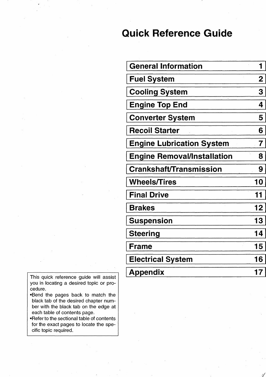
This quick reference guide will assist you in locating a desired topic or pro- cedure. -Send the pages back to match the black tab of the desired chapter num- ber with· the black tab on the edge at each table of contents page. -Refer to the sectional table of contents for the exact pages to locate the spe- cific topic required. Quick Reference Guide General Information 1 Fuel System 2 Cooling System 3 Engine Top End 4 ConverterSy~em 5 Recoil Starter 6 Engine Lubrication System 7 Engine Removal/Installation 8 CrankshaftfTransmission 9 I Wheelsrrires 10. I Final Drive 11 I Brakes 12 I Suspension 13 Steering 14 Frame 15 Electrical System 16 Appendix 17
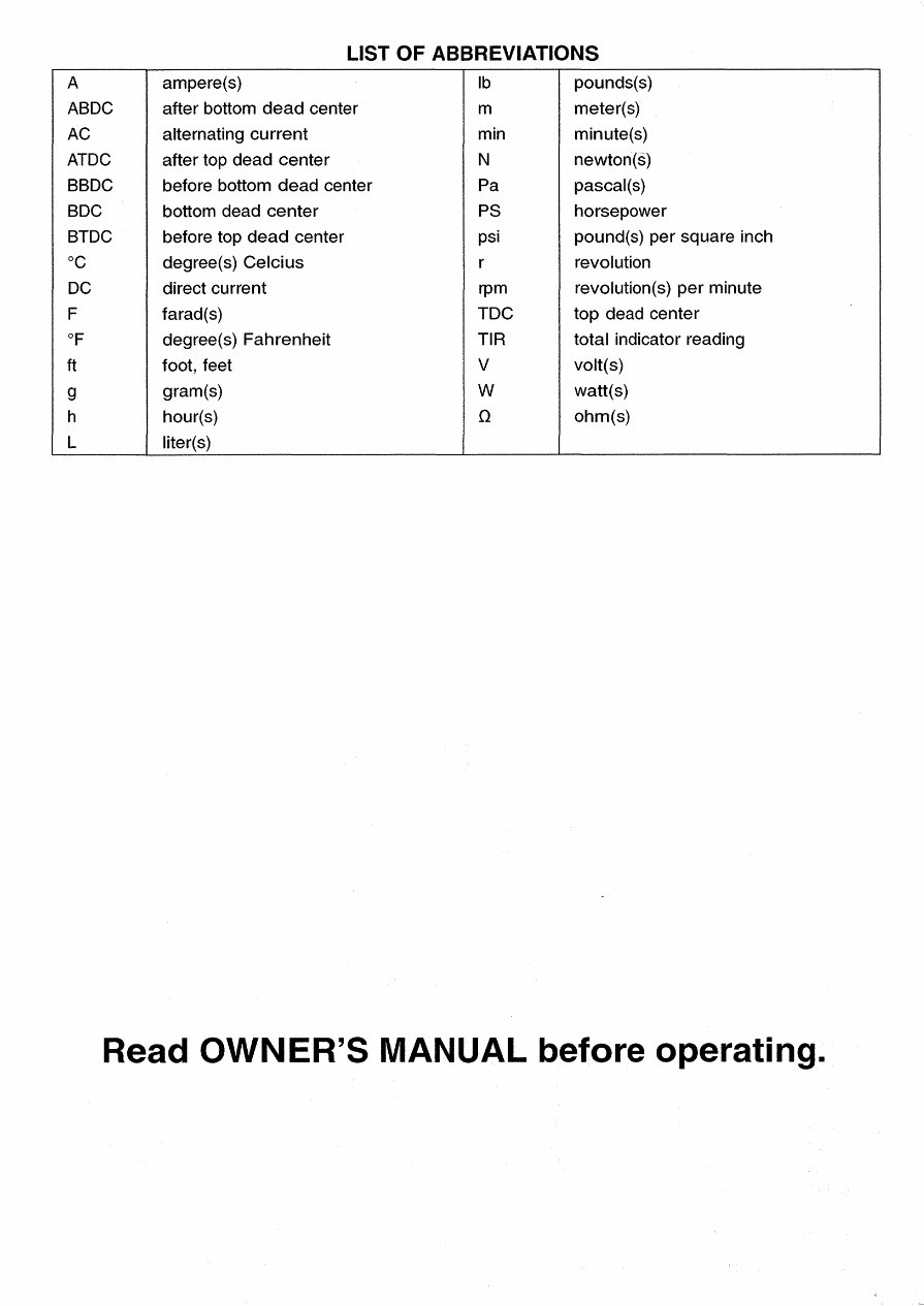
LIST OF ABBREVIATIONS A ampere(s) Ib pounds(s) ABDC after bottom dead center m meter(s) AC alternating current min minute(s) ATDC after top dead center N newton(s) BBDC before bottom dead center Pa pascal(s) BDC bottom dead center PS horsepower BTDC before top dead center psi pound(s) per square inch °C degree(s) Celcius r revolution DC direct current rpm revolution(s) per minute F farad(s) TOC top dead center of degree(s) Fahrenheit TIR total indicator reading ft foot, feet V volt(s) g gram(s) W watt(s) h hour(s) n ohm(s) L liter(s) Read OWNER'S MANUAL before operating.
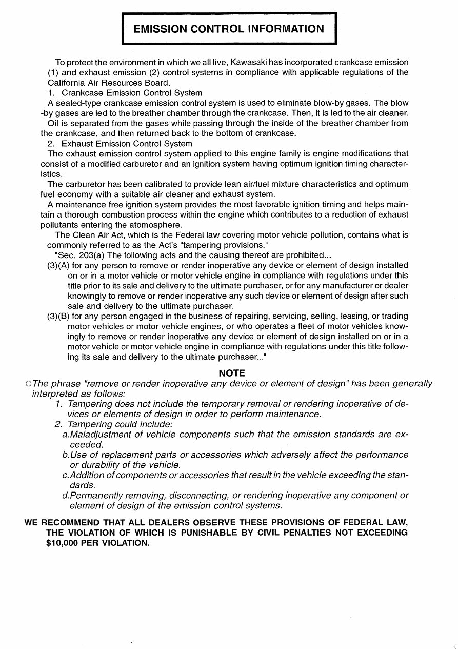
I EMISSION CONTROL INFORMATION I To protect the environment in which we all live, Kawasaki has incorporated crankcase emission (1) and exhaust emission (2) control systems in compliance with applicable regulations of the California Air Resources Board. 1. Crankcase Emission Control System A sealed-type crankcase emission control system is used to eliminate blow-by gases. The blow -by gases are led to the breather chamber through the crankcase. Then, it is led to the air cleaner. Oil is separated from the gases while passing through the inside of the breather chamber from the crankcase, and then returned back to the bottom of crankcase. 2. Exhaust Emission Control System The exhaust emission control system applied to this engine family is engine modifications that consist of a modified carburetor and an ignition system having optimum ignition timing character- istics. The carburetor has been calibrated to provide lean air/fuel mixture characteristics and optimum fuel economy with a suitable air cleaner and exhaust system. A maintenance free ignition system provides the most favorable ignition timing and helps main- tain a thorough combustion process within the engine which contributes to a reduction of exhaust pollutants entering the atomosphere. The Clean Air Act, which is the Federal law covering motor vehicle pollution, contains what is commonly referred to as the Act's "tampering provisions." "Sec. 203(a) The following acts and the causing thereof are prohibited ... (3)(A) for any person to remove or render inoperative any device or element of design installed on or in a motor vehicle or motor vehicle engine in compliance with regulations under this title prior to its sale and delivery to the ultimate purchaser, or for any manufacturer or dealer knowingly to remove or render inoperative any such device or element of design after such sale and delivery to the ultimate purchaser. (3)(B) for any person engaged in the business of repairing, servicing, selling, leasing, or trading motor vehicles or motor vehicle engines, or who operates a fleet of motor vehicles know- ingly to remove or render inoperative any device or element of design installed on or in a motor vehicle or motor vehicle engine in compliance with regulations under this title follow- ing its sale and delivery to the ultimate purchaser .. :' NOTE o The phrase IIremove or render inoperative any device or element of design II has been generally interpreted as follows: 1. Tampering does not include the temporary removal or rendering inoperative of de- vices or elements of design in order to perform maintenance. 2. Tampering could include: a.Maladjustment of vehicle components such that the emission standards are ex- ceeded. b. Use of replacement parts or accessories which adversely affect the performance or durability of the vehicle. c.Addition of components or accessories that result in the vehicle exceeding the stan- dards. d.Permanently removing, disconnecting, or rendering inoperative any component or element of design of the emission control systems. WE RECOMMEND THAT ALL DEALERS OBSERVE THESE PROVISIONS OF FEDERAL LAW, THE VIOLATION OF WHICH IS PUNISHABLE BY CIVIL PENALTIES NOT EXCEEDING $10,000 PER VIOLATION.
PLEASE DO NOT TAMPER WITH NOISE CONTROL SYSTEM (US MODEL only) To minimize the noise emissions from this product, Kawasaki has equipped it with effective intake and exhaust silencing systems. They are designed to give optimum performance while maintaining a low noise level. Please do not remove these systems, or alter them in any which results in an increase in noise level.
Foreword This manual is designed primarily for use by trained mechanics in a properly equipped shop. However, it contains enough detail and basic in- formation to make it useful to the owner who de- sires to perform his own basic maintenance and repair work. A basic knowledge of mechanics, the proper use of tools, and workshop proce- dures must be understood in order to carry out maintenance and repair satisfactorily. When- ever the owner has insufficient experience or doubts his ability to do the work, all adjust- ments, maintenance, and repair should be car- ried out only by qualified mechanics. In order to perform the work efficiently and to avoid costly mistakes, read the text, thor- oughly familiarize yourself with the procedures before starting work, and then do the work care- fully in a clean area. Whenever special tools ?r equipment are specified, do not use makeshift tools or equipment. Precision measurements can only be made if the proper instruments are used, and the use of substitute tools may ad- versely affect safe operation. For the duration of the warranty period, we recommend that all repairs and scheduled maintenance be performed in accordance with this service manual. Any owner maintenance or repair procedure not performed in accordance with this manual may void the warranty. To get the longest life out of your vehicle: • Follow the Periodic Maintenance Chart in the Service Manual. • Be alert for problems and non-scheduled maintenance. • Use proper tools and genuine Kawasaki Vehi- cle parts. Special tools, gauges, and tester~ that are necessary when servicing Kawasaki vehicles are introduced by the Special Tool Catalog or Manual. Genuine parts provided as spare parts are listed in the Parts Catalog. • Follow the procedures in this manual care- fully. Don't take shortcuts. • Remember to keep complete records of main- tenance and repair with dates and any new parts installed. How to Use This Manual In preparing this manual, we divided the prod- uct into its major systems. These systems be- came the manual's chapters. All information for a particular system from adjustment through disassembly and inspection is located in a sin- gle chapter. The Quick Reference Guide shows you all of the product's system and assists in locating their chapters. Each chapter in turn has its own comprehensive Table of Contents. The Periodic Maintenance Chart is located in the General Information chapter. The chart gives a time schedule for required maintenance operations. If you want spark plug information, for exam- ple, go to the Periodic Maintenance Chart first. The chart tells you how frequently to clean and gap the plug. Next, use the Quick Reference Guide to locate the Electrical System chapter. Then, use the Table of Contents on the first page of the chapter to find the Spark Plug sec- tion. Whenever you see these WARNING and CAUTION symbols, heed their instructions! Always follow safe operating and maintenance practices. A. WARNING This warning symbol identifies special instructions or procedures which, if not correctly followed, could result in per- sonal injury, or loss of life. CAUTION This caution symbol identifies special instructions or procedures which, if not strictly observed, could result in dam- age to or destruction of equipment. This manual contains four more symbols (in addition to WARNING and CAUTION) which will help you distinguish different types of informa- tion.
NOTE o This note symbol indicates points of par- ticular interest for more efficient and con- venient operation . • Indicates a procedural step or work to be done. Olndicates a procedural sub-step or how to do the work of the procedural step it follows. It also precedes the text of a NOTE. * Indicates a conditional step or what action to take based on the results of the test or inspec- tion in the procedural step or sub-step it fol- lows. In most chapters an exploded view illustration of the system components follows the Table of Contents. In these illustrations you will find the instructions indicating which parts require spec- ified tightening torque, oil, grease or a locking agent during assembly.
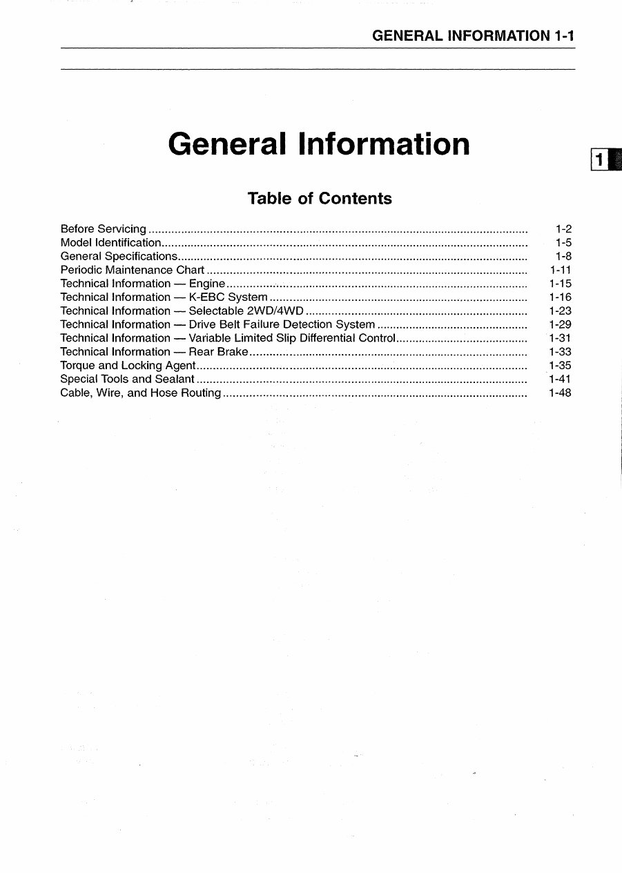
GENERAL INFORMATION 1-1 General Information Table of Contents Before Servicing..................................................................................................................... 1-2 Model Identification ....................................................... ,.................... ............. ............ ...... ...... 1-5 General Specifications............................................................................................................ 1-8 Periodic Maintenance Chart................................................................................................... 1-11 Technical Information - Engine............................................................................................. 1-15 Technical Information - K-EBC System ................................................................................ 1-16 Technical Information - Selectable 2WO/4WD ........ ............................................................. 1-23 Technical Information - Drive Belt Failure Detection System ., .... .... ........... .... .... .... ...... ........ 1-29 Technical Information - Variable Limited Slip Differential Control...... ....... ...... .... .... ........ ...... 1-31 Technical Information - Rear Brake...................................................................................... 1-33 Torque and Locking Agent...................................................................................................... 1-35 Special Tools and Sealant...................................................................................................... 1-41 Cable, Wire, and Hose Routing.............................................................................................. 1-48
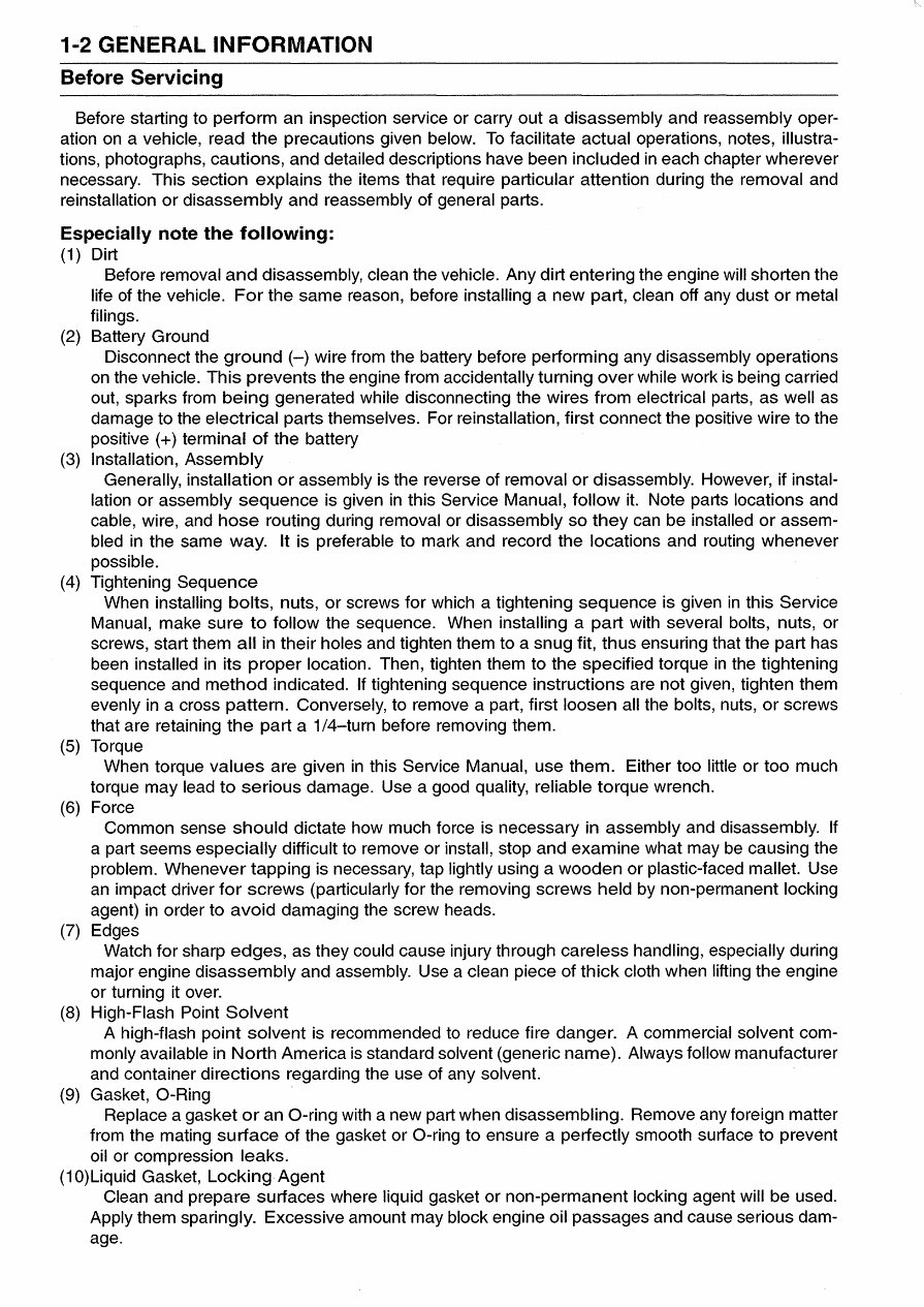
1-2 GENERAL INFORMATION Before Servicing Before starting to perform an inspection service or carry out a disassembly and reassembly oper- ation on a vehicle, read the precautions given below. To facilitate actual operations, notes, illustra- tions, photographs, cautions, and detailed descriptions have been included in each chapter wherever necessary. This section explains the items that require particular attention during the removal and reinstallation or disassembly and reassembly of general parts. Especially note the following: (1) Dirt Before removal and disassembly, clean the vehicle. Any dirt entering the engine will shorten the life of the vehicle. For the same reason, before installing a new part, clean off any dust or metal filings. (2) Battery Ground Disconnect the ground (-) wire from the battery before performing any disassembly operations on the vehicle. This prevents the engine from accidentally turning over while work is being carried out, sparks from being generated while disconnecting the wires from electrical parts, as well as damage to the electrical parts themselves. For reinstallation, first connect the positive wire to the positive (+) terminal of the battery (3) Installation, Assembly Generally, installation or assembly is the reverse of removal or disassembly. However, if instal- lation or assembly sequence is given in this Service Manual, follow it. Note parts locations and cable, wire, and hose routing during removal or disassembly so they can be installed or assem- bled in the same way. It is preferable to mark and record the locations and routing whenever possible. (4) Tightening Sequence When installing bolts, nuts, or screws for which a tightening sequence is given in this Service Manual, make sure to follow the sequence. When installing a part with several bolts, nuts, or screws, start them all in their holes and tighten them to a snug fit, thus ensuring that the part has been installed in its proper location. Then, tighten them to the specified torque in the tightening sequence and method indicated. If tightening sequence instructions are not given, tighten them evenly in a cross pattern. Conversely, to remove a part, first loosen all the bolts, nuts, or screws that are retaining the part a 1/4-turn before removing them. (5) Torque When torque values are given in this Service Manual, use them. Either too little or too much torque may lead to serious damage. Use a good quality, reliable torque wrench. (6) Force Common sense should dictate how much force is necessary in assembly and disassembly. If a part seems especially difficult to remove or install, stop and examine what may be causing the problem. Whenever tapping is necessary, tap lightly using a wooden or plastic-faced mallet. Use an impact driver for screws (particularly for the removing screws held by non-permanent locking agent) in order to avoid damaging the screw heads. (7) Edges Watch for sharp edges, as they could cause injury through careless handling, especially during major engine disassembly and assembly. Use a clean piece of thick cloth when lifting the engine or turning it over. (8) High-Flash Point Solvent A high-flash pOint solvent is recommended to reduce fire danger. A commercial solvent com- monly available in North America is standard solvent (generic name). Always follow manufacturer and container directions regarding the use of any solvent. (9) Gasket, a-Ring Replace a gasket or an a-ring with a new part when disassembling. Remove any foreign matter from the mating surface of the gasket or a-ring to ensure a perfectly smooth surface to prevent oil or compression leaks. (10)Liquid Gasket, Locking Agent Clean and prepare surfaces where liquid gasket or non-permanent locking agent will be used. Apply them sparingly. Excessive amount may block engine oil passages and cause serious dam- age.
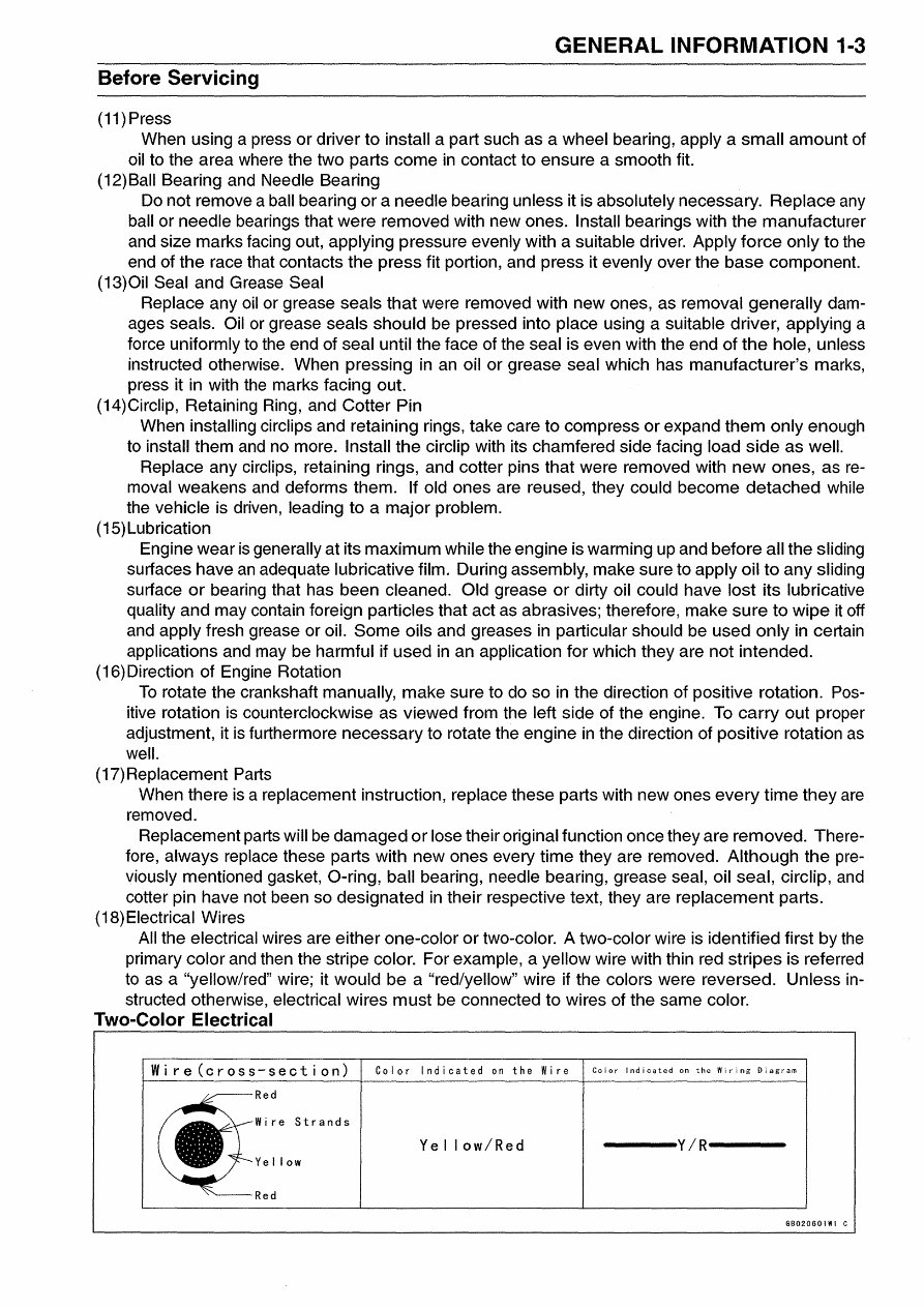
GENERAL INFORMATION 1-3 Before Servicing (11) Press When using a press or driver to install a part such as a wheel bearing, apply a small amount of oil to the area where the two parts come in contact to ensure a smooth fit. (12)Ball Bearing and Needle Bearing Do not remove a ball bearing or a needle bearing unless it is absolutely necessary. Replace any ball or needle bearings that were removed with new ones. Install bearings with the manufacturer and size marks facing out, applying pressure evenly with a suitable driver. Apply force only to the end of the race that contacts the press fit portion, and press it evenly over the base component. (13)Oil Seal and Grease Seal Replace any oil or grease seals that were removed with new ones, as removal generally dam- ages seals. Oil or grease seals should be pressed into place using a suitable driver, applying a force uniformly to the end of seal until the face of the seal is even with the end of the hole, unless instructed otherwise. When pressing in an oil or grease seal which has manufacturer's marks, press it in with the marks facing out. (14)Circlip, Retaining Ring, and Cotter Pin When installing circlips and retaining rings, take care to compress or expand them only enough to install them and no more. Install the circlip with its chamfered side facing load side as well. Replace any circlips, retaining rings, and cotter pins that were removed with new ones, as re- moval weakens and deforms them. If old ones are reused, they could become detached while the vehicle is driven, leading to a major problem. (15)Lubrication Engine wear is generally at its maximum while the engine is warming up and before all the sliding surfaces have an adequate lubricative film. During ass-embly, make sure to apply oil to any sliding surface or bearing that has been cleaned. Old grease or dirty oil could have lost its lubricative quality and may contain foreign particles that act as abrasives; therefore, make sure to wipe it off and apply fresh grease or oil. Some oils and greases in particular should be used only in certain applications and may be harmful if used in an application for which they are not intended. (16) Direction of Engine Rotation To rotate the crankshaft manually, make sure to do so in the direction of positive rotation. Pos- itive rotation is counterclockwise as viewed from the left side of the engine. To carry out proper adjustment, it is furthermore necessary to rotate the engine in the direction of positive rotation as well. (17) Replacement Parts When there is a replacement instruction, replace these parts with new ones every time they are removed. Replacement parts will be damaged or lose their original function once they are removed. There- fore, always replace these parts with new ones every time they are removed. Although the pre- viously mentioned gasket, O-ring, ball bearing, needle bearing, grease seal, oil seal, circlip, and cotter pin have not been so designated in their respective text, they are replacement parts. (18) Electrical Wires All the electrical wires are either one-color or two-color. A two-color wire is identified first by the primary color and then the stripe color. For example, a yellow wire with thin red stripes is referred to as a "yellow/red" wire; it would be a "red/yellow" wire if the colors were reversed. Unless in- structed otherwise, electrical wires must be connected to wires of the same color. Two-Color Electrical Wire(cross-section) Color Indicated on the Wire Color Indicated on the Wiring Diagram Red Wire Strands Ye I low/Red -------Y/R------- Ye II ow Red GB020601WI C
This is a comprehensive service repair manual for the KAWASAKI PRAIRIE 650, KVF 650, PRAIRIE 650 4X4, KVF 650 4X4 ATV, covering production model years 2002-2003. It provides complete information similar to factory shop manuals or CDROM manuals used in repair shops, making it suitable for both professional mechanics and DIY enthusiasts.
This professional quality, highly detailed service repair workshop manual provides step-by-step instructions, exploded pictures, and diagrams to facilitate effortless completion of simple to complicated repairs. It covers the entire vehicle and is the same type of manual used by professional mechanics. The manual is compatible with Windows 7, Vista 32 and 64, XP, ME, 98, NT, 2000, and Mac. It is instantly accessible upon receipt of payment, and all pages are printable for easy reference during repairs, making it a cost-effective resource for vehicle maintenance.
Recently Viewed
5,521,897Happy Clients
2,594,462eManuals
1,120,453Trusted Sellers
15Years in Business
Price:
Actual Price:
2002-2003 Kawasaki Prairie 650 KVF 650 Prairie 650 4X4 KVF 650 4X4 All Terrain Vehicle Service & Repair Manual