Kawasaki BA YOU 400 4x4 KLF4004x4 All Terrain Vehicle Service Manual
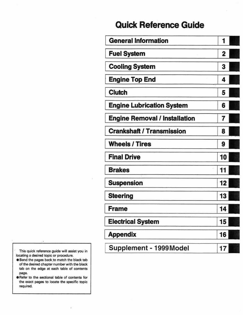
This quick reference guide will assist you in locating a desired topic or procedure. •Bend the pages back. to match the black tab of the desired chapter number with t he black tab on the edge at each table of contents paga •Refer to the sectional tab le of contents for the e>Cact pages to locate the specific topic required. Quick Reference Guide General Information Fuel System Cooling System Engine Top End Clutch Engine Lubrication System Engine Removal / Installation Crankshaft I Transmission Wheels I Tires Final Drive Brakes Suspension I Steering Frame Electrical System I Appendix Supplement - 1999Model 1 2 3 4 5 6 7 8 9 10 11 12 13 14 j 1s 1 1& j 11
Kawasaki BA YOU 400 4x4 KLF4004x4 A ll Terrain Vehicle Service Manual All rights reserved. No parts of this publication may be reproduced, stored in a retrieval system, or transmitted in any form or by any means, electronic mechanical photocopying, recording or otherwise, without the prior written permission of Quality Assurance Department/Consumer Products & Components Group/ Kawasaki Heavy Industri es, Ltd .. Japan. No liability can be accepted for any inaccuracies or omissions in this publication, although every possible care has been taken to make it as complete and accurate as possible. The right is reserved to make changes at any time without prior notice and without incurring an obligation to make such changes to products manufactured previously. See your dealer for the latest Information on product improvemepts incorporated after this publication. All information contained in this publication is based on the latest product information available at the time of publication. Illustrations and photographs in this publication are intended for reference use only and may not depict actual model component parts. CO Kawasaki Heavv Industries. ltd. 1992, 1994, 1995. 1996 , 1999 Fifth Edition (1 ): Nov. 30, 1999 (K)
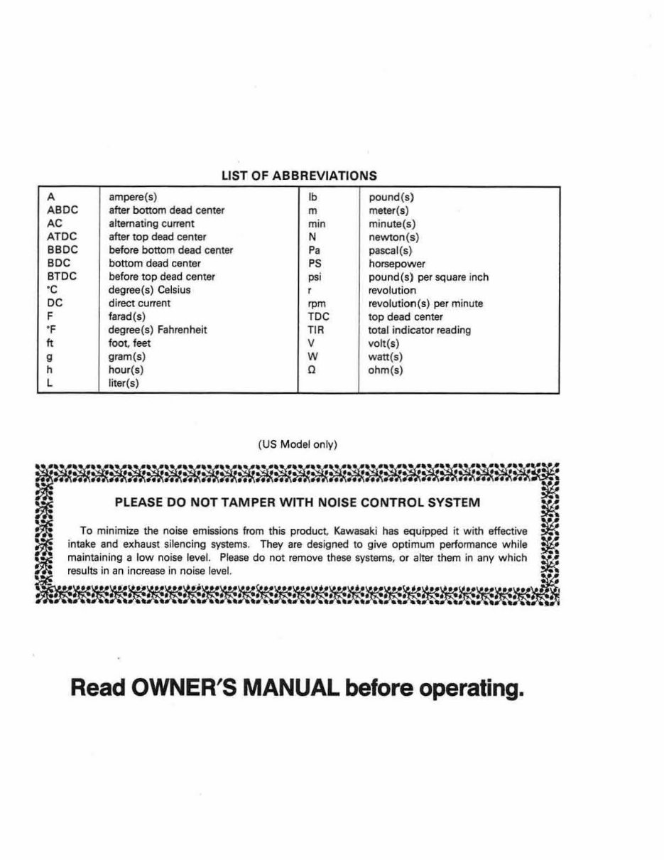
LIST OF ABBREVIATIONS A ampere(s) lb pound(s) ABDC after bottom dead center m meter(s) AC alternating current min minute(s) ATDC after top dead center N newton(s) BBDC before bottom dead center Pa pascal(s) BOC bottom dead center PS horsepower BTDC before top dead center psi pound{s) per square inch ·c degree(s) Celsius r revolution DC direct current rpm revolution(s) per minute F farad(s) TDC top dead center "F degree(s) Fahrenheit TIA total indicator reading ft foot, feet v volt(s) g gram(s) w watt(s) h hour(s) 0 ohm(s) L liter(s) (US Model only) ~~~~~~~~~~~~~~~~~~~~~~~~ ~ PLEASE DO NOT TAMPER WITH NOISE CONTROL SYSTEM ~ ~ To minimize the noise emissions from this product, Kawasaki has equipped it with effective ~ ~ intake and exhaust silencing systems. They are designed to give optimum performance while ~ ~ maintaining a low noise level. Please do not remove these systems, or alter them in any which !f~ ~~~;;~~~~~~~~~~~~~~ Read OWNER'S MANUAL before operating.
Foreword Th is manual is designed primarily for use by trained mechanics in a properly equipped shop. However, it contains enough detail and basic information to make it usefu l to the owner who desires to perform his own basic maintenance and repair work. A basic knowledge of mechanics, the proper use of tools, and workshop procedur es must be understood in order to carry out maintenance and repair satisfactorily. Whenever the owner has insufficient experience or doubts his ability to do the work, all adjustments, maintenance, and repair should be carried out only by qualified mechanics. In order to perform the work efficiently and to avoid costly mistakes, read the text, thoroughly familiarize yourself with the procedures before Starting work, and then do the work carefully in a clean area. Whenever special tools or equipment are specified, do not use makeshift tools or eq uipment. Precision measurements can only be made if the proper instruments are used, and the use of substi- tute tools may adversely affect safe operation. For the duration of the warranty period , we recommend that all repairs and scheduled maintenance be performed In accordance with this service manua l. Any owner maintenance or repair procedure not performed in accordance w ith this manual may void the warranty. To get the longest life out of your Vehicle: • Follow the Periodic Maintenance Chart in the Service Manual. • Be alert for problems and non-scheduled ma inte- nance. e Use proper tools and genuine Kawasaki vehicle parts. Special tools, gauges, and testers that are necessary when servicing Kawasak i vehicles are introduced by the Special Tool Catalog or Manual. Genu ine parts provided as spare parts are listed in the Parts Catalog. eFollow the procedures in this manual carefully. Don't take shortcuts. • Remember to keep complete records of ma inte- nance and repair with dates and any new parts installed. How to Use this Manual In preparing this manual. we divided the product into its major systems. These systems became the manual's chapters. All information for a particular system from adjustment through disassembly and inspection is located in a single chapter. The Quick Reference Guide shows you all of the product's system and assists in locating their chapters. Each chapter in turn has its own compre- hensive Table of Contents. The Periodic Maintenance Chart is located in the General Information chapter. The chart gives a time schedule fo r required maintenance operations. If you want spark plug information, for example, go to the Periodic Ma intenance Chart first. The chart tells you how frequently to clean and gap the plug. Next, use the Qu ick Reference Guide to locate the Electrical System chapter. Then, use the Table of Contents on the first page of the chapter to find the Spark Plug secti on. Whenever you see these WARNING and CAUTION symbols, heed their instructionsl Always follow safe operating and ma intenance practices. "\WARNING This warning symbol identifies special instructions or procedures which, if not correctly followed, could result in personal injury, or loss of life. CAUTION This caution symbol identifies special in struct i ons or procedures which, if not strictly observed,. could result in damage to or destruction of equipment.
This manual contains four more symbols (in addition to WARNING and CAUTION) which will help you distinguish different types of information. NOTE o This note symbol indicates points of particular interest for more efficient and convenient operation. •Indicates a procedural step or work to be done. o Indicates a procedural sub-step or how to do the work of the procedural step it follows. It also precedes the text of a NOTE. *Ind icates a conditional step or what action to take based on the results of the test or inspection in the procedural step or sub-step it follows. In most chapters an exploded view illustration of the system components follows the Table of Contents. In these illustrations you will find the instructions indicating which parts require specified tightening torque, oil. grease or a locking agent during assembly.
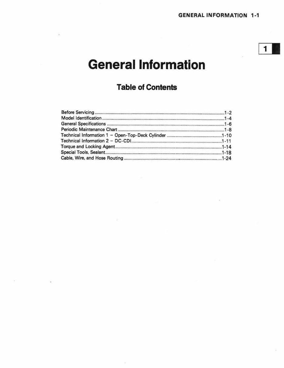
GENERAL INFORMATION 1-1 General Information Table of Contents Before Servicing ...................... .. ... ........................................................... - .................. 1-2 Model Identification ................................................... .. ...............................................1 -4 General Specifications .................................... ... ................................ .. ....................... 1-6 Periodic Maintenance Chart .......................................................................................1 · 8 Technical Information 1 - Open-Top-Deck Cylinder ............................................. 1-10 Technical Information 2 - DC-CDl ....................................... .. ... .............................. 1-11 Torque and Locking Agent ................................ .. ......... .. .......................................... 1- 14 Special Tools, Sealant ......................................... .. ...................- ............................... 1-18 Cable, Wire, and Hose Routing .. ..................................................... .. ..................... .. 1-24
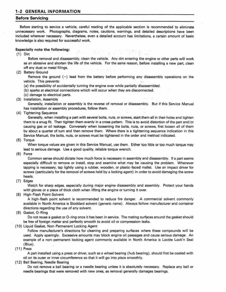
1-2 GENERAL INFORMATION Before Servicing Before starting to service a vehicle, careful reading of the applicable section is recommended to eliminate unnecessary work. Photographs, diagrams, notes, cautions, warnings, and detailed descriptions have been included wherever necessary. Nevertheless, even a detailed account has limitations, a certain amount of basic knowledge is also required for successful work. Especiall y not e the fo llo wing : (1) Dirt ·. Before removal and disassembly, clean the vehicle. Any dirt entering the engine or other parts w ill work as an abrasive and shorten the life of the vehicle. For the same reason, before installing a new part, clean oft any dust or metal filings. (2) Battery Ground Remove the ground ( - ) lead from the battery before performing any disassembly operations on the vehicle. This prevents: ~ (a) the possibility of accidentally turning the engine over while partially disassembled. ( b) sparks at electrical connections which will occur when they are disconnected. (c) damage to electrical parts. (3) Installation, Assembly Generally, installation or assembly is the reverse of removal or disassembly. But if this Service Manual has installation or assembly procedur es, follow them. (4) Tightening Sequence Generally, when installing a part with several bolts, nuts, or screws, start them all in their holes and tighten them to a snug fit. Then tighten them evenly in a cross pattern. This is to avoid distortion of the part and/ or causing gas or oil lea kage. Conversely when loosening the bolts, nuts, or screws, first loosen all of them by about a quarter of tum and then remove them. Where there is a tightening sequence indication in this Service Manual, the bolts, nuts, or screws must be tightened in the order and method indicated. (5) Torque When torque values are given in this Service Manual, use them. Either too little or too much torque may lead to serious damage. Use a good quality, reliable torque wr ench. (6) Force Common sense should dictate how much force is necessary in assembly and disassembly. If a part seems especially difficult to remove or install, stop and examine what may be causing the problem. Whenever tapping is necessary, tap lightly using a rubber, wooden, or plastic-faced mallet. Use an impact driver for screws (particularly for the removal of screws held by a locking agent) in order to avoid damaging the screw heads. (7) Edges Watch for sharp edges, especially during major engine disassembly and assembly. Protect your hands with gloves or a piece of thick cloth when lifting the engine or turning it over. (8) High-Flash Point Solvent A high-flash point solvent is recommended to reduce fire danger. A commercial solvent commonly available in North America is Stoddard solvent (generic name). Always follow manufacturer and container directions regarding the use of any solvent. (9) Gasket, 0 - Ring Do not reuse a gasket or 0 -ring once it has been in service. The mating surfaces around the gasket should be free of foreign matter and perfectly smooth to avoid oil or compression leaks. (10) Liquid Gasket, Non-Permanent Locking Agent Follow manufacturer's directions for cleaning and prepari ng surfaces where these compounds will be used. Apply sparingly. Excessive amounts may block engine oil passages and cause serious damage. An example of a non -permanent locking agent commonly available in North America is Loctite Lock'n Sea l (Blue). (1 1) Press A part installed using a press or dr iver, such as a wheel bearing ( hub bearing), should first be coated with oil on its outer or inner circumference so that it w ill go into place smoothly. ( 12) Ball Bearing, Needle Beari ng Do not remove a ball beari ng or a needle bearing unless it is absolutely necessary. Replace any ball or needle bearings that were removed with new ones, as removal generally damages bearings.
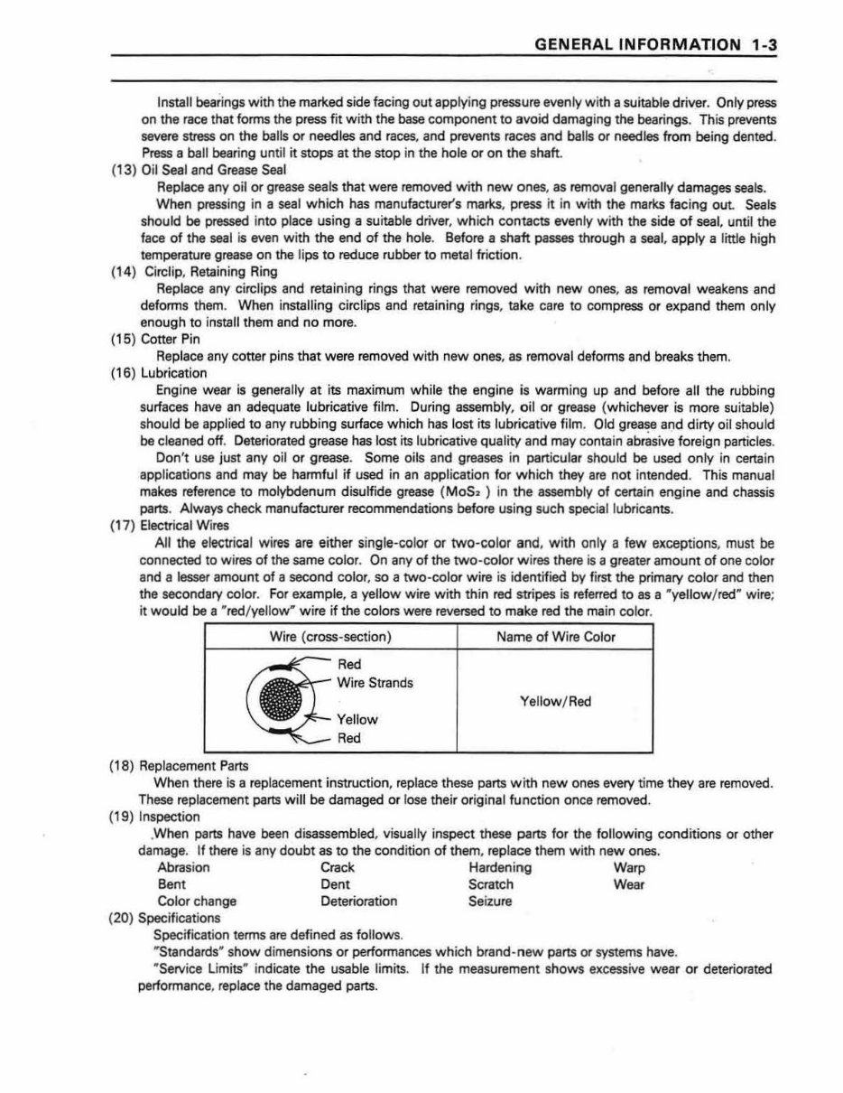
GENERAL INFORMATION 1-3 Install bearings w ith the marked side facing out applying pressure evenly with a suitable driv~r. Only press on the race that forms the press fit with the base component to avoid damaging the bearings. This prevents severe stress on the balls or needles and races, and prevents races and balls or needles from being dented. Press a ball bearing unt il it stops at the stop in the hole or on the shaft . (13) Oil Seal and Grease Seal Replace any oil or grease seals that were removed w i th new ones, as removal generally damages seals. When pressing in a seal wh ich has manufacturer's marks, press it in with the marks faci ng out Seals should be pressed into place using a suitable driver, wh ich contacts evenly with the side of seal. until the face of the seal is even with the end of the hole. Before a shaft passes through a seal, apply a little high temperature grease on the lips to reduce rubber to metal friction. (1 4) Circlip, Retaining Ring Replace any circlips and retaining rings that were removed with new ones, as removal weakens and deforms them. When installing circlips and retaining rings, take care to compress or expand them only enough to install them and no more. (15) Cotter Pin Replace any cotter pins that were removed with new ones, as, removal deforms and breaks them. (16) Lubrication Engine wear is generally at its maximum wh ile the engine is warming up and before all the rubbing surfaces have an adequate lubricative film. During assembly, oil or grease (whichever is more suitable) should be applied to any rubbing surface which has lost its lubricative film. Old grea~e and dirty oil should be clea ned off. Deteriorated grease has lost its lubricative quality and may contain abrasive foreign particles. Don' t use just any oil or grease. Some oils and greases in particular should be us.ed only in certain applications and may be harmful if used in an application for which they are not intended. This manual makes reference to molybdenum disulfide grease ( Mos~ ) in the assembly of certain engine and chassis parts. Always check manufacturer recommendations before using such special lubricants. (17) Electrical Wires All the electrical wires are either single-color or two-color and, w ith only a few exceptions, must be connected to wi res of the same color. On any of the two -color w ires there is a greater amount of one color and a lesser amou nt of a second color, so a two-co lor w ire is identified by first the primary color and then the secondary color. For example, a yellow wire wi th thin red stripes is referred to as a "yellow / red" wire; it would be a " red / yellow" wire if the colors were reversed to make red the main color. (18) Replacement Parts Wire (cross-section) Red Wire Strands Yellow Red Name of Wi re Color Yellow/Red When there is a replacement instruction, replace these parts with new ones every time they are removed. These replacement parts will be damaged or lose their original fu nction once removed. (19) Inspection .When parts have been disassembled, visually inspect these parts for the following conditions or other damage. If there is any doubt as to the condition of them, replace them with new ones. Abrasion Crack Hardening Warp Bent Dent Scratch Wear Color change Deterioration Seizure (20) Specifications Specification terms are defined as follows. "Standards" show dimensions or performances which brand -n ew parts or systems have. "Service Limits" indicate the usable limits. If the measurem ent show s excessive w ear or deteriorated performance, replace the damaged parts.
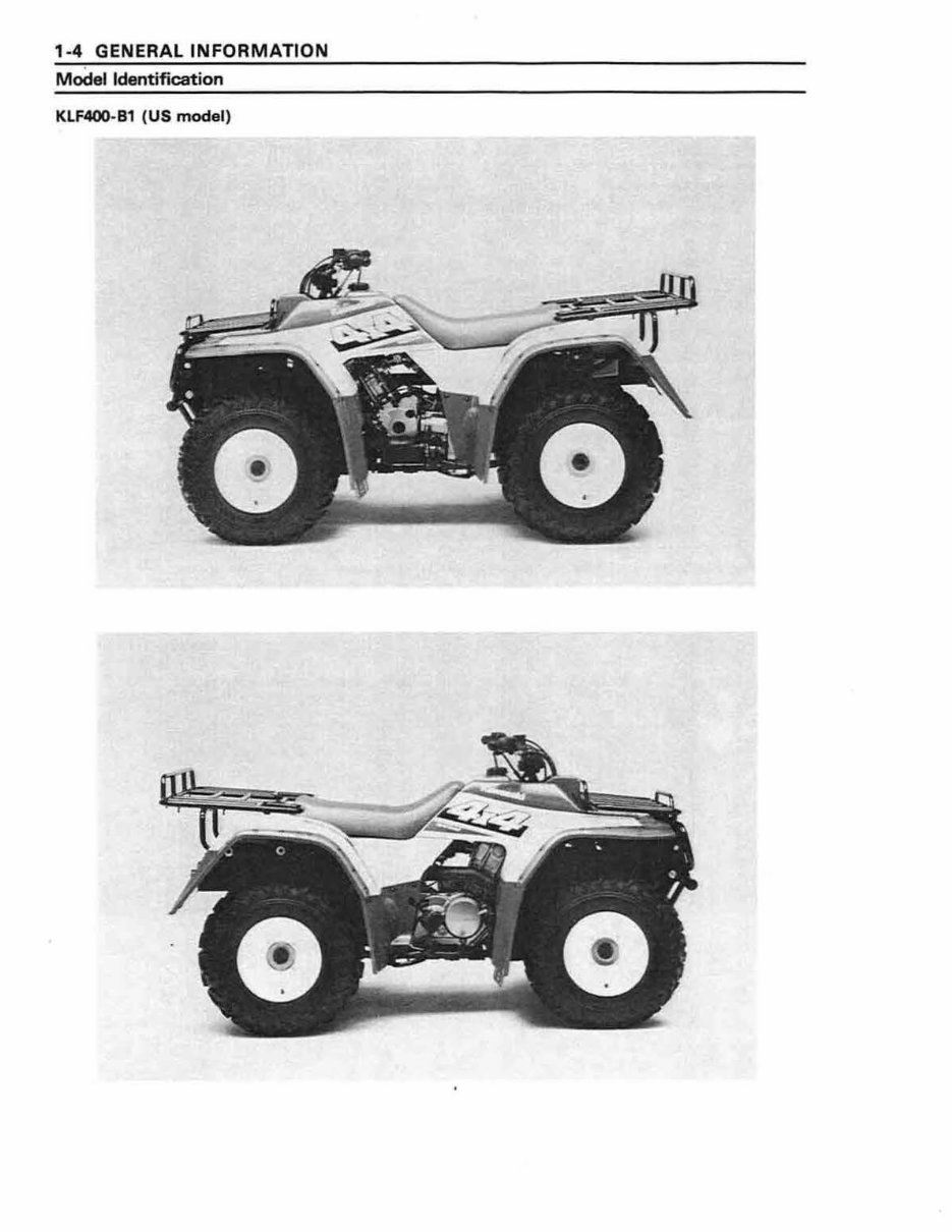
1-4 GENERAL INFORMATION Model Identification KLF400- B1 (US model)
The 1996 Kawasaki Bayou 400 (KLF400) 4x4 ATV OEM Service & Repair Manual is a comprehensive guide containing all the necessary information for repairing, maintaining, rebuilding, refurbishing, or restoring your 1996 Kawasaki Bayou 400 (KLF400) ATV. It covers detailed diagnostic and repair procedures, making it a valuable resource for both professional technicians and do-it-yourself mechanics.
This manual is part of a series of practical repair and service guides used by mechanics worldwide. It includes:
Repair procedures and service schedules
Maintenance tips and wiring diagrams
Diagnostic procedures with detailed sub-steps
Notes, cautions, and warnings for critical information
Numbered instructions with highlighted figure numbers
Detailed illustrations, drawings, and photographs with enlarged insets for parts identification
The manual also features a numbered table of contents for easy navigation, troubleshooting, and electrical service procedures combined with comprehensive wiring diagrams. It is provided in .PDF format, compatible with all versions of Windows and Mac, and is fully printable for convenient offline access without the need for shipping physical copies.
This Service & Repair Manual covers an extensive range of topics, including:
General information and specifications
Engine removal and reassembly
Wiring diagrams and lubrication points
Oil types, periodic maintenance, and tune-up procedures
Engine servicing and complete engine service steps
Fuel and lubrication systems including carburetor rebuild and adjustments
Electrical systems, ignition, battery, and starter details
Chassis assembly, brakes, steering, suspension, and wheels
Service data, wire/cable/hose routing, tools, and tightening torques
Gearbox, exhaust system, fault finding, clutch removal/installation, transmission, and front suspension
U-joint and CV joint service procedures, timing chain service, and additional repair topics
In summary, the 1996 Kawasaki Bayou 400 (KLF400) 4x4 ATV OEM Service & Repair Manual is an indispensable resource for anyone looking to repair or maintain their ATV. It provides comprehensive and detailed repair information for both professional technicians and DIY enthusiasts.