1986-2004 Kawasaki Bayou 300 KLF 300 Service & Repair Manual
What's Included?
Lifetime Access
Fast Download Speeds
Online & Offline Access
Access PDF Contents & Bookmarks
Full Search Facility
Print one or all pages of your manual
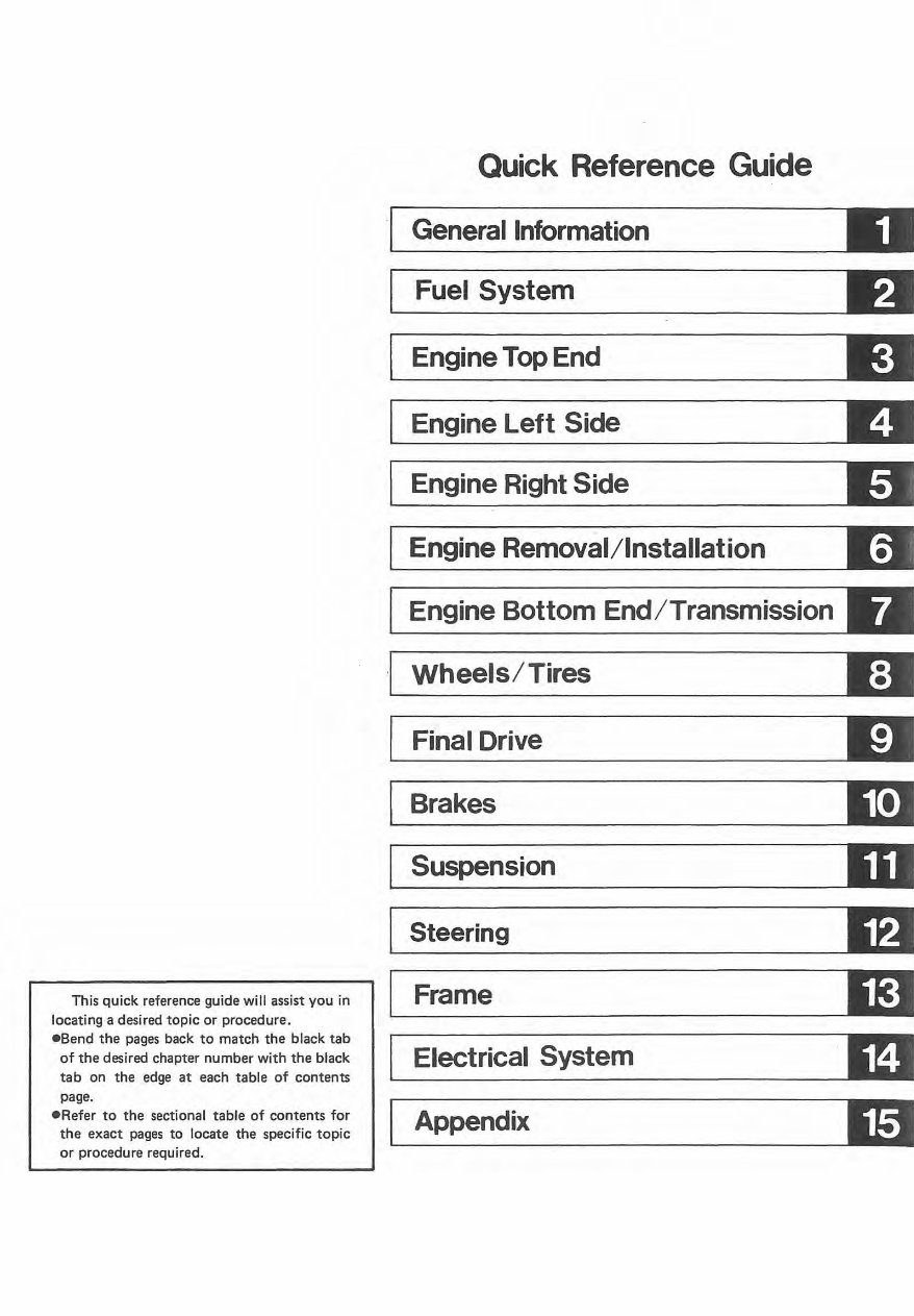
This quick reference guide will assist you in locating a desired topic or procedure. eSend the pages back to match the black tab of the desired chapter number with the black tab on the edge at each tab le of contents page. eRefer to the sectional table of contents for the exact pages to locate the spec ific topic or procedure requ ired. Quick Reference Guide ·L J _G_e_n_e_r_ al _l_n_ fo_r_m_a_ t_ io_n _____ ----.J D I Fuel System .:w L--. _____ K:iI I Engine Top End .:II L- . ____ Ell Engine Left Side Engine Right Side Engine Removal/Installation Engine Bottom End/Transmission Wheels/Tires Final Drive Brakes Suspension Steering Frame Electrical System Appendix
Kawasaki KLF300 All Terrain Vehicle Service Manual
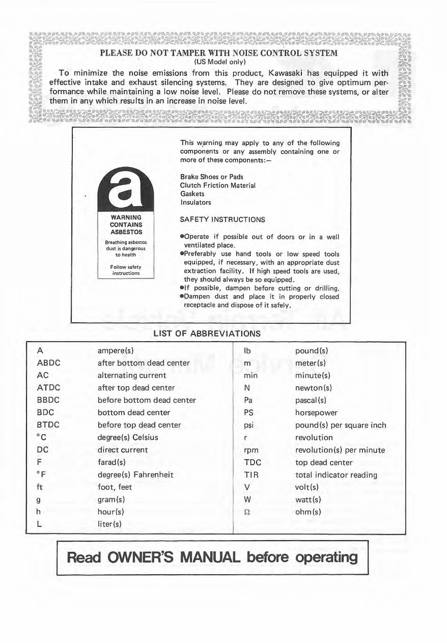
~l:;~~%~~w;:~~:V:~;'~:~~:>"~~,~:&~~'!!~:}.~:>"~~'l:~{~C:~~:.'v.(;'fJ:-;~~~;t>.'~~V~~~ ~~~n.~1ti~~~~~d;;l!!..'i\)~¢~~*~~{ui~~~¥~~~~r~~l!tJa.c~~d~~~~*,~ ~ PLEASE DO NOT TAMPER WITH NOISE CONTROL SYSTEM ~ ~ (US Model onlyl ~ ~% To minimize the noise emissions from this product, Kawasaki has equipped it with ~ ~ effective intake and exhaust silencing systems. They are designed to give optimum per- A ... S~ formance while maintaining a low noise level. Please do not remove these systems, or alter ~ ~ them in any which results in an increase in noise level. ~ "'~"~".~~"~~~' "''II~~'~~,,~~--~~qSl~."~ · . w:~~~~-~.m. ~~ .,,~ ~61!,~""$1 ~~ . , :tr(.~~li d";,. JI).xt't it .~-l<er~ .... r •. tI '! t~ 'It ~t,. ';;o¥'!. ""... ~;;<,; . ". ,..... ,," nA ...." ~'ii II ." .tf~" " ....... " "'" .. :?<''i. R if ..... A ABDC AC ATDC BBDC BDC BTDC °C DC F OF ft g h L WARNING CONTAINS ASBESTOS Breathing asbestos dust is dangerous to health Fol low safety instructions This w,arning may apply to any of the following components or any assembly containing one or more of these components:- Brake Shoes or Pads Cl utch Friction Material Gaskets Insulators SAFETY INSTRUCTIONS -Operate if possible out of doors or in a well ventilated place. .Preferably use hand tools or low speed tools equipped, if necessary, with an appropriate dust extraction facility. If high speed tools are used, they should always be so equipped . • If possible, dampen before cutting or drilling . • Dampen dust and place it in properly closed receptacle and dispose of it safely. LIST OF ABBREVIATIONS ampere(s) Ib pound(s) after bottom dead center m meter(s) alternating current min minute(s) after top dead center N newton(s) before bottom dead center Pa pascal (s) bottom dead center PS horsepower before top dead center psi pound(s) per square inch degree(s) Celsius r revolut ion direct current rpm revolution(s) per minute farad(s) TDC top dead center degree(s) Fahrenheit TIR total indicator reading foot, feet V volt(s) gram(s) W watt(s) hour(s) S1 ohm(s) liter(s) Read OWNER'S MANUAL before operating
Foreword This manual is designed primarily for use by trained mechanics in a properly equipped shop. However, it contains enough detail and basic information to make it useful to the owner who desires to perform his own basic maintenance and repair work. A basic knowledge of mechan- ics, the proper use of tools, and workshop procedures must be understood in order to carry out maintenance and repair satisfactorily. Whenever the owner has insufficient experience or doubts his ability to do the work, all adjust- ments, maintenance, and repair should be carried out only by qualified mechanics. In order to perform the work efficiently and to avoid costly mistakes, read the text, thor- oughly familiarize yourself with the procedures before starting· work, and then do the work carefully in a clean area. Whenever special tools or equipment are specified, do not use makeshift tools or equipment . Precision measurements can only be made if the proper instruments are used, and the use of substitute tools may adversely affect safe operation. For the duration of your warranty period, especially, we recommend that all repairs and scheduled maintenance be performed in accord- ance with this service manual. Any owner maintenance or repair procedure not performed in accordance with this manual may void the warranty. To get the longest life out of your vehicle: - Follow the Periodic Maintenance Chart in the Service Manual. -Be alert for problems and non-scheduled maintenance. -Use proper tools and genuine Kawasaki vehicle parts. Special tools, gauges, and testers that are necessary when servicing Kawasaki vehicles are introduced by the Special Tool Manual. Genuine parts provided as spare parts are listed in t he Parts Catalog. -Follow the procedures in this manual carefully. Don't take shortcuts. _ Remember to keep complete records of main- tenance and repair with dates and any new parts installed. How to Use this Manual In preparing this manual, we divided the product into its major systems. These systems became the manual's chapters. All information for a particular system from adjustment through disassembly and inspection is located in a single chapter. The Quick Reference Guide shows you all of the product's systems and assists in locating their chapters. Each chapter in turn has its own comprehensive Table of Contents. The Periodic Maintenance Chart is located in the General Information chapter. The chart gives a time schedule for required maintenance operations. If you want spark plug information, for example, go to the Periodic Maintenance Chart first. The chart tells you how frequently to clean and gap the plug. Next, use the Quick Reference Guide to locate the Electrical System chapter. Then, use the Table of Contents on the first page of the chapter to find the Spark Plug section. Whenever you see these WARNING and CAUTION symbols, heed their instructions! Always follow safe operating and maintenance practices. I WARNING. oThis warning symbol identifies special instruc- tions or procedures which, if not correctly followed, could result in personal injury, or loss of life. oThis caution symbol identifies special instruc- tions or procedures which, if not strictly observed, could result in damage to or destruc- tion of equipment. This manual contains five more symbols (in addition to WARNING and CAUTION) which will help you distinguish different types of information. NOTE o This note symbol indicates points of particular interest for more efficient and convenient operation.
elndicates a procedural step or work to be done. o lndicates a procedural sub-step or how to do the work of the procedural step it follows. It also precedes the text of a WARNING, CAUTION, or NOTE. *Indicates a conditional step or what action to take based on the results of the test or inspec- tion in the procedural step or sub-step it follows. <r Indicates a conditional sub-step or what action to take based upon the results of the condi- tional step it follows. In most chapters an exploded view illustration of the system components follows the Table of Contents. In these illustrations you will find the instructions indicating which parts require specified tightening torque, oil, grease or a locking agent during assembly.
'-2 GENERAL INFORMATION Before Servicing Before starting to service a vehicle, careful reading of the applicable section is recommended to eliminate unnecessary work. Photographs, diagrams, notes, cautions, warnings, and detailed des- criptions have been included wherever necessary. Nevertheless, even a detailed account has limi- tations, a certain amount of basic knowledge is also required for successful work. Especially note the following: (1) Dirt Before removal and disassembly, clean the vehicle. Any dirt entering the engine or - other parts will work as an abrasive and shorten the life of the vehicle. For the same reason, before installing a new part, clean off any dust or metal filings. (2) Battery Ground Remove the ground (-) lead from the battery before performing any disassembly operations on the vehicle. This prevents: (a) the possibility of accidentally turning the engine over while partially disassembled. (b) sparks at electrical connections which will occur when they are disconnected. (c) damage to electrical parts. (3) Tighten ing Sequence Generally, when installing a part with several bolts, nuts, or screws, start them all in their holes and tighten them to a snug fit. Then tighten them evenly in a cross pattern. This is to avoid distortion of the part and/or causing gas or oil leakage. Conversely when .loosening the bolts, nuts, or screws, first loosen all of them by about a quarter of turn and then remove them. Where there is a tightening sequence indication in this Service Manual, the bolts, nuts, or screws must be tightened in the order and method indicated. (4) Torque When torque values are given in this Service Manual, use them. Either too little or too much torque may lead to serious damage. Use a good quality, reliable torque wrench. (5) Force Common sense should dictate how much force is necessary in assembly and disassembly. If a part seems especially difficult to remove or install, stop and examine what may be causing the problem. Whenever tapping is necessary, tap lightly using a wooden or plastic-faced mallet. Use an impact driver for screws (particularly for the removal of screws held by a locking agent) in order to avoid damaging the screw heads. (6) Edges Watch for sharp edges, especially during major engine disassembly and assembly. Protect your hands with gloves or a piece of thick cloth when lifting the engine or turning it over. (7) High-Flash Point Solvent A high-flash point solvent is recommended to reduce fire danger. A commercial solvent com- monly available in North America is Stoddard solvent (generic name). Always follow manufac- turer and container directions regarding the use of any solvent. (B) Gasket, O-Ring Do not reuse a gasket or O-ring once it has been in service. The mating surfaces around the gasket should be free of foreign matter and perfectly smooth to avoid oil or compression leaks. (9) Liquid Gasket, Non-Permanent Locking Agent Follow manufacturer's directions for cleaning and preparing surfaces where these compounds will be used. Apply sparingly. Excessive amounts may block engine oil passages and cause serious damage. An example of a non-permanent locking agent commonly available in North America is Loctite Lock'n Seal (Blue) . (10) Press A part installed using a press or driver, such as a wheel bearing, should first be coated with oil on its outer or inner circumference so that it w ill go into place smoothly . (11) Ball Bearing When installing a ball bearing, the bearing race which is affected by friction should be pushed by a su itable driver. This prevents severe stress on the balls and races, and prevents races and balls from being dented . Press a ball bearing until it stops at the stop in the hole or on the shaft.
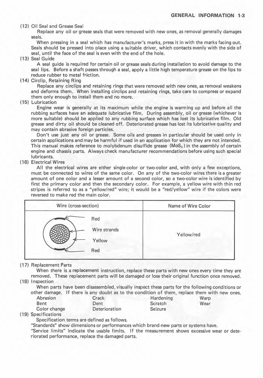
GENERAL INFORMATION 1-3 (12) Oil Seal and Grease Seal Replace any oil or grease seals that were removed with new ones, as removal generally damages seals. When pressing in a seal which has manufacturer's marks, press it in with the marks facing out. Seals should be pressed into place using a suitable driver, which contacts evenly with the side of seal, until the face of the seal is even with the end of the hole. (13) Seal Guide A seal guide is required for certain oil or grease seals during installation to avoid damage to the seal lips. Before a shaft passes through a seal, apply a little high temperature grease on the lips to reduce rubber to metal friction. (14) Circlip, Retaining Ring Replace any circlips and retaining rings that were removed with new ones, as removal weakens and deforms them. When installing circlips and retaining rings, take care to compress or expand them only enough to install them and no more. (15) Lubrication Engine wear is generally at its maximum wh il e the engine is warming up and before all the rubbing surfaces have an adequate lubricative film. During assembly, oil or grease (whichever is more suitable) should be applied to any rubbing surface which has lost its lubricative film. Old grease and dirty oil should be cleaned off . Deteriorated grease has lost its lubricative quality and may contain abrasive foreign particles. Don't use just any oil or grease. Some oils and greases in particular should be used only in certain applications and may be harmful if used in an application for which they are not intended. This manual makes reference to molybdenum disulfide grease (MoS,) in the assembly of certain engine and chassis parts. Always check manufacturer recommendations before using such special lubricants. (16) Electrical Wires All the electrical wires are either single- color or two-color and, with only a few exceptions, must be connected to wires of the same color. On any of the two - color wires there is a greater amount of one color and a lesser amount of a second color, so a two·color wire is identified by first the primary color and then the secondary color. For example, a yellow wire with thin red stripes is referred to as a "yellow/red" wire; it would be a "red/yellow" wire if the colors were reversed to make red the main color. Wire (cross-section) Name of Wire Color e: Red ~~ Wire strands r Yellow/ red f-- Yellow .... '" Red (17) Replacement Parts When there is a replacement instruction, replace these parts with new ones every time they are removed. These replacement parts will be damaged or lose their original function once removed. (18) Inspection When parts have been disassembled, visually inspect these parts for the following conditions or other damage. If there is any doubt as to the condition of them, replace them with new ones. Abrasion Crack Hardening Warp Bent Dent Scratch Wear Color change Deterioration Seizure (19) Specifications Specification terms are defined as follows. "Standards" show dimensions or performances which brand-new parts or systems have. "Service limits" indicate the usable limits. If the measurement shows excessive wear or dete- riorated performance, replace the damaged parts.
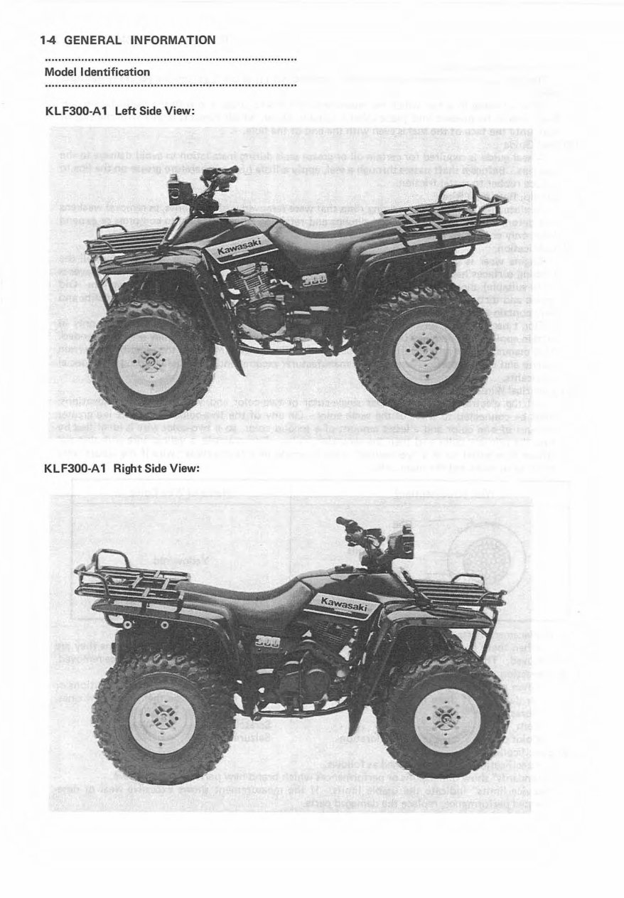
14 GENERAL INFORMATION Model Identification KLF300-A 1 Left Side View: KLF300-A 1 Right Side View:
Get your hands on the complete workshop service repair manual for the Kawasaki Bayou 300 KLF 300 spanning from 1986 to 2006. This comprehensive manual is an invaluable resource for both professional mechanics and DIY enthusiasts.
The manual encompasses every service and repair procedure, providing easy-to-follow step-by-step instructions and detailed images for all areas of servicing and repairs. By utilizing this manual, you can significantly reduce expenses by undertaking your own repairs.
Once acquired, the manual is yours to keep indefinitely. You have the flexibility to print individual pages, chapters, or the entire manual. Additionally, it can be conveniently accessed on your tablet or smartphone.
All models, engines, trim, and transmission types are covered in this manual, ensuring its applicability across a wide range of variations.
This high-quality service repair workshop manual comprehensively covers all repair procedures from A to Z, leaving no aspect untouched.
Compatible with all PC and MAC computers, tablets, and mobile phones, this downloadable manual requires only Adobe Reader, which is commonly pre-installed on most devices or can be obtained for free.
Upon payment via Visa, MasterCard, or PayPal, the manual will be promptly emailed to the address provided during checkout, ensuring instant delivery.
Rest assured, customer satisfaction is guaranteed with this comprehensive workshop service repair manual.
Recently Viewed
5,521,897Happy Clients
2,594,462eManuals
1,120,453Trusted Sellers
15Years in Business
Price:
Actual Price:
1986-2004 Kawasaki Bayou 300 KLF 300 Service & Repair Manual