Downloaded from www.Manualslib.com manuals search engine
, • I • I l. GENERAL INFORMATION GENERAL SAFETY SERVICE RULE S MODEL IDENTIFICATION SPECIFICATIONS GENERAL SAFETY , -, ,-, ' -2 ' -3 TOROUE VALUES TOOLS CABLE & HARN ESS ROUTING NOISE EMI SSION CONTROL SYSTEM .¥ ' -5 ' -6 ' -7 '- '0 I Jthe en,ine must lu runninl to do some work, moke sure the arellis well·ventilated. Never run the engine in a closed area, The waust contains poisonous cQrbon monoxide gas. Gasoline is utr~m~/y ftlJmmllb/~ and l! up /osive under urtain conditions. Do not smoke or allow flames or sptJrk.s in your work Qrea. SERVICE RULES 1. Use genuine HONDA or HONDA-recommended parts and lubricants or their eQuivale nts . Parts that don't meet HONDA's design specifications may cause damage to the Fourtrax. 2. Use the special tools designed for this product to avoid damage and incorrect assembly. 3. Use only metric tools when servicing this Fourtrs x. Metric bolts, nut s and screws are nOl interchangeable with English fas- teners. 4. Install new gaskets , O-rings. cotter pins and lock plates when reassembling. 5. When tightening bolts or nuts , begin with the larger-diameter or inner bolts first . Then tighten to the specified torque diag- onally in 2 or 3 steps. unless a particular sequence is specified. 6. Clean parts in non-flammable or high flash point sol vent upon disassembly . 7. Lubricate any sliding surfaces before reassembly. 8. After reassembly. check all part s for proper installation and operation. 1-1 Downloaded from www.Manualslib.com manuals search engine
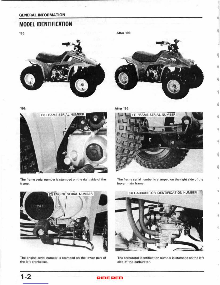
GENERAL INFORMATION MODEL IDENTIFICATION ' S6 : '86 : t 1 I FRAME SE.IIAL NUI~~ The frame se rial number is stamped on the right side of th e frame. The engine serial number is stamped on the lowe r part of the left crankcase. 1-2 Afte r ' 86 : After ' S6 : The frame serial number is sta mped on the right side of the lower main frame. (31 CARBURETOR IDENTIFI CATION NUMBER The carburetor identification number is stamped on the l eft side of the carbur etor. • , • • • • • I Downloaded from www.Manualslib.com manuals search engine
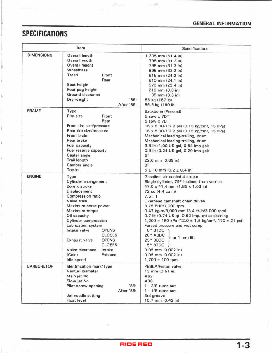
I • SPECIFICATIONS Item DIMENSIONS Overall length OV8ra1l width Overall height Wheelbase Tread Front Reaf Seat height Foot peg height Ground clearance Dry weight FRAME Type Rim size Front Rear Front tire size/pressure Rear tire size/pressure Front brake Rear brake Fuel capacity Fuel reserve capacity Caster angle Trail length Camber angle Toe-in ENGINE Type Cyl inder arrangement Bore x stroke Displacement Compression ratio Valve train Maximum horse power M aximum torque Oil capacity Cylinder compression lubrication system Intake valve OPENS CLOSES Exhaust valve OPENS CLOSES Valve clearance Intake (Cold) Exhaust Idle speed CARBURETOR Identification mar klType Venturi diameter Main jet No. Slow jet No. Pilot screw opening Jet needle setting Float level GENERAL INFORMATION Specifications 1,305 mm (51 .4 in) 795 mm (31.3 in) 795 mm (31.3 in) 895 mm (33.2 in) 615 mm 124.2 in) 610 mm (24.1 in) 570 mm (22 .4 in) 210 mm (8.3 in ) 85 mm (3.3 in) '86 : 85 kg 1187 Ib) After '86: 86 .5 kg (190 Ib) Backbone (Pressed) 5 spw x 70T 5 spw x 70T 16 x 8.00-7/ 2.2 psi (0.15 kglc m 2 , 15 kPa) 16 x 8.00-7 / 2.2 psi (0.15 kg /cm 2 , 15 kPa ) Mechanical leading-trailing, drum Mechanical leading-trailing, drum 3.8 lit 11.00 US gal, 0.84 Imp gal) 0.9 lit 10.24 US gal, 0.20 Imp gal) 5° 22.6 mm (0.89 inl 0° 5::1: 10 mm (0.2::1: 0.4 in) Gasoline, air-cooled 4-stroke Single cylinder, 75 0 inclined from vertical 47 .0 x 41.4 mm /1 .85 x 1 .63 in) 72 cc 14.4 cu in) 7.5 : 1 Overhead camshaft chain driven 3. 75 BHP/7,000 rpm 0.4 7 kg-m/3, OOO rpm 13.4 ft-lb/ 3,OOO rpm) 0 .7 lit 10 . 74 US Qt , 0.62 Imp. Qt ) at draining 1,200 ± 150 kPa (12 .0 ± 1.5 kg / cm 2 , 170::1: 21 psi) Forced pressure and wet sump 00 BTDC } ,\1 mm lift 20 0 ABDC 25 0 BBOC 50 BTDC 0. 05 mm (0. 002 in) 0_ 05 mm (0.002 in ) 1 ,700 ± 100 rpm PB86A/Piston valve 13 mm (0.51 in) #.2 #38 '86: 1 - 3/8 turns out After '86: 1 - 1/8 turns out 3rd groove , 0 .7 mm (0.42 in) 1-3 Downloaded from www.Manualslib.com manuals search engine
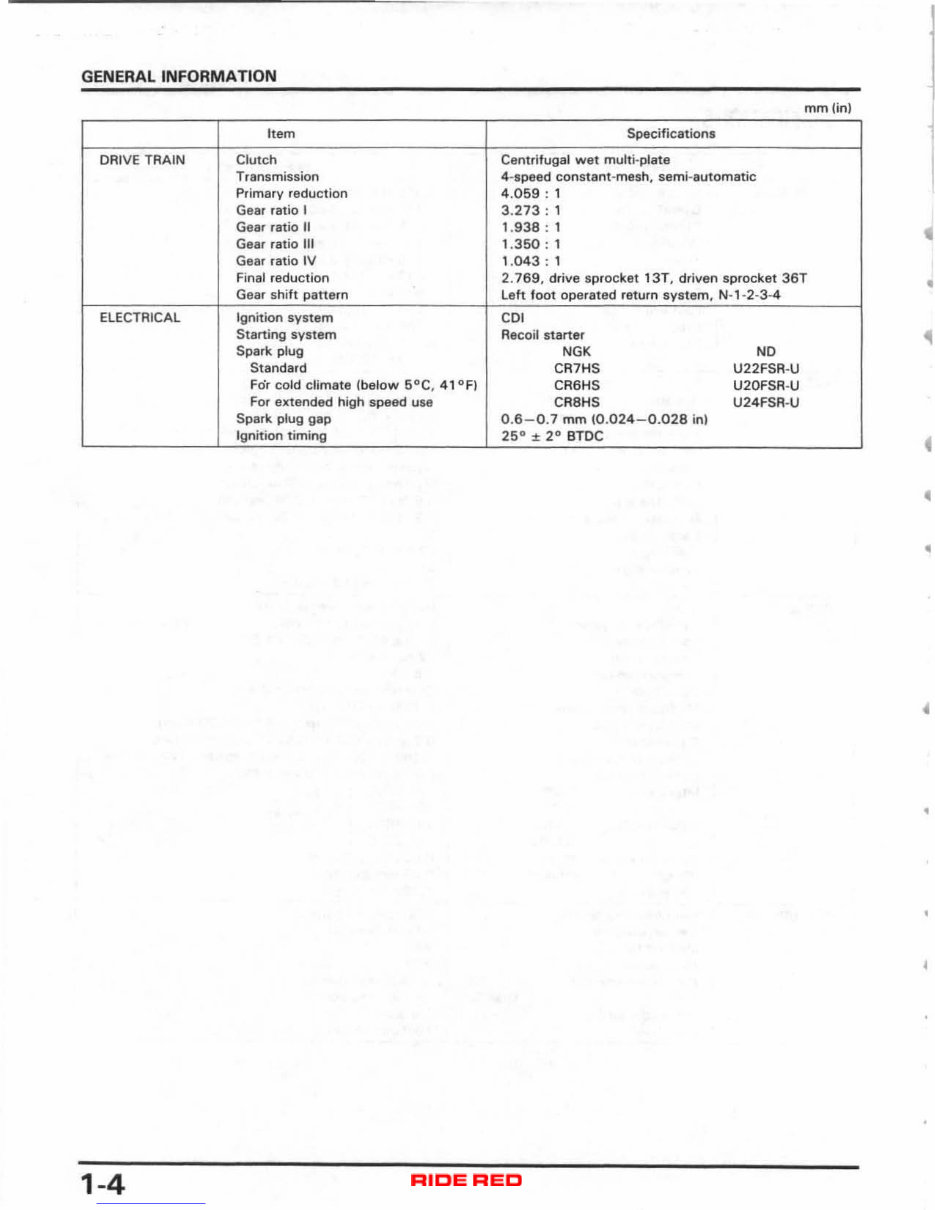
GENERAL INFORMATION mm(in) I tem Specifications DRIVE TRAIN Clutch Centrifugal wet multi-plate Transmission 4-speed constant -mesh, semi - automatic Primary reduction 4.059 : 1 Gear ratio I 3. 273 : 1 Gear ratio II 1.938 : 1 Gear ratio III 1.350 : 1 Gear ratio tv 1.043 : 1 Final reduction 2. 769, drive sprocket 13T, dri ven sprocket 36T • Gear shift pattern Left foot operated return system, N-1-2-3-4 ELECTRICAL Ignition system CO l Starting system Recoil starter Spark plug NGK NO Standard CR7HS U22FSA-U For cold climate (below 5°C , 41°F) CR6HS U20FSA·U For extended high speed use CR8HS U24FSR·U Spark plug gap 0 .6 - 0.7 mm (0.024 - 0.028 in) Ignition timing 25 ° ± 2° BTDC 4 • , 1-4 Downloaded from www.Manualslib.com manuals search engine
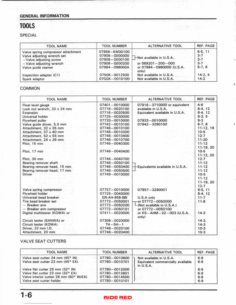
GENERAL INFORMATION TOOLS SPECIAL TOOL NAME TOOL NUMBER AL TEANATI VE TOOL REF . PAGE Valve spring compressor attachment 07959 - KM30100 6·5 , 11 Valve adjusting wrench set 07908-GEOOOOO P-Not available in U.S.A. 3-7 -Va lve adjusting screw 07908 - GEOO100 3-7 • -Valve adjusting wrench 0790B - GEOO200 or 089201 - 200 - 000 3-7 Valve guide reamer 01984-0geOOOA or 07984 - 0980000 IU .S.A. 6-7, 8 only) Inspection adapter Ie 1) 07508 - 0012500 Not available in U.S.A. 14-2 .4 Spark adaptor 07GGK-0010100 Not available in U.S. A. 14-2 • COMMON TOOL NAME TOOL NUMBER Al TERNA TI VE TOOL REF . PAGE Float level gauge 07401 -00 10000 07916 - 3710000 or equivalent 4-6 Lock nut wrench, 20 x 24 mm 07716 -0020100 available in U.S.A. 8 -4 , 12 Extension 07716-0020500 Equivalent available in U.S.A. 8-4, 12 Universal holder 07725-0030000 9-3. 5 Flywheel puller 07733-00 10000 07933 - 0010000 9-3 Valve guide driver. 5.5 mm 07742-0010100 07942 - 3290100 6-7.8 • Attachment. 32 x 35 mm 07746 -0010100 11 - 12, 19 Attachment, 37 x 40 mm 07746 - 0010200 10-. Attachment, 52 x 55 mm 07746 - 0010400 12-7 Attachmant, 24 x 26 mm 07746 - 0010700 11 - 20 Pilot, 15 mm 07746 - 0040300 1 ' -1 2 1' - 19 , 20 Pilot, 17 mm 07746-0040400 10-. 11-12, 20 Pilot. 30 mm 07746 - 0040700 12-7 Bearing remover shaft 07746-0050100 ~EqUiValents available in U. S.A. 11 - 12 Bearing remover head, 15 mm 07746 - 0050400 11 - 12 Bearing ramover head, 17 mm 07746 - 0050500 11 - 12 Driver 07749-0010000 10-. 11 - 12 11 - 19, 20 12-7 Valve spring compressor 07757 -001 0000 07957 - 3290001 6-6 , 11 Flywheel holder 07725-0040000 8-4 , 12 Universal bead breaker GN-AH- 958 · BBI U.S.A only 11 -7 Tire bead breaker set 07772-0050001 lc~r07772 - oo50000 11 -8 - Breaker arm 07772 - 0050200 (Not available in U.S.A.) - Breaker arm compressor 07772 -0050 101 or 07772 - 0050100 Digital multitester (KOWAl Of 0741' -0020000 or KS-AHM-32 - oo3 (U.S.A. 14-3 only) Circuit tester (SANWAI or 07308-0020000 14-3 Circuit tester (KOWA) TH - 5H- l 14-3 Driver, 22 mm 1.0. 07746 -00 20100 10-3 Attachment. 20 mm 07746 -00 20400 10-3 VALVE SEAT CUTTERS TOOL NAME TOOL NUMBER ALTERNATIVE TOOL REF . PAGE Valve seat cutter 24 mm 145 0 IN) 07780-0010600 Not available in U.S.A. 6-9 Valve seat cutter 22 mm 145 0 EX) 07780 - 0010701 Equivalent commercially available 6-9 in U.S.A. Valve flat cutter 25 mm 132 0 IN) 07780-0012000 6-9 Valve flat cutter 22 mm (32° EX) 07780 - 0012601 6-9 Valve interior cutter 26 mm (60 0 IN/EX) 07780 - 0014500 6-9 Valva seat cuttar holder 07780 - 0010101 6-9 1-6 Downloaded from www.Manualslib.com manuals search engine
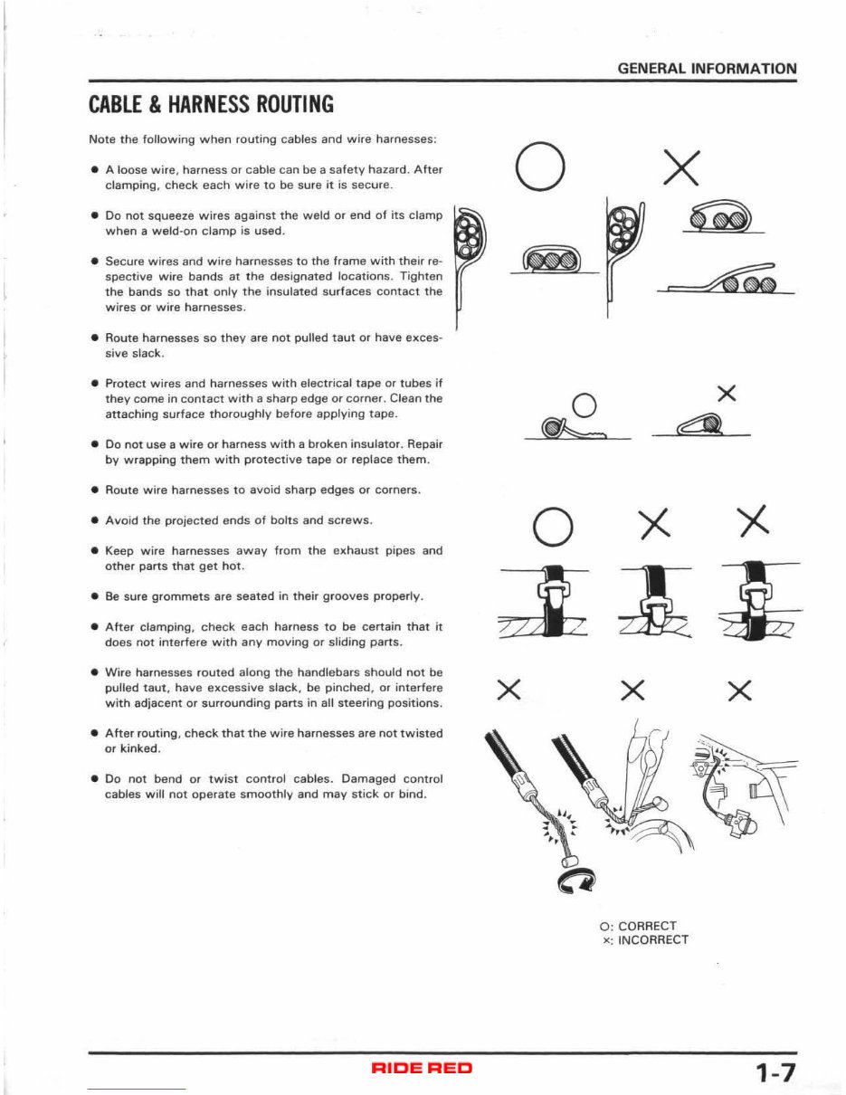
CABLE & HARNESS ROUTING Note the foHowing when routing cables and wire harnesses: • A loose wi re, harness or cable can be a saf ety hazard. Aher clamping, check each wire to be sure it is secure. • Do not squeeze wires against the weld or end of its clamp when a weld-on clamp is used. • Secure wires and wire harnesses to the frame with their re- spective wire bands at the designated locations. Tighten t he bands so that only the insulated surfaces contact the wires or wire harnesses. • Aoute harnesses so they are not pulled taut or have eJ:ces- sive slack. • Protect wir es and harnesses with electrical tape or tubes if they come in contact with a sharp edge or corner. Clean the attaching surface thoroughly before applying tape. • 00 not use a wi re or harness with a broken insulator . Repair by wrapping them with protective tape or replace them. • Route wire harnesses to avoid sharp edges or corners. • Avoid the projected ends of bolts and screws. • Keep wi re harnesses away from the exhaust pipes and ot her parts that get hot. • Be sure grommets are seated in their grooves properly. • Afte r clamping, check each harness to be certain that it does not interfere with any moving or sliding parts . • Wire harnesses routed along the handlebars should not be pulled taut , have excessive slack, be pinched, or interfere with adjacent or surrounding parts in all steering positions. • Afte r routing, check that the wire harnesses are not twisted or kinked . • Do not bend or twist control cables. Damaged control cables will not operate smoothly and may stick or bind . o x GENERAL INFORMATION x X Q x 0: CORRECT x; INCORRECT 1-7 Downloaded from www.Manualslib.com manuals search engine
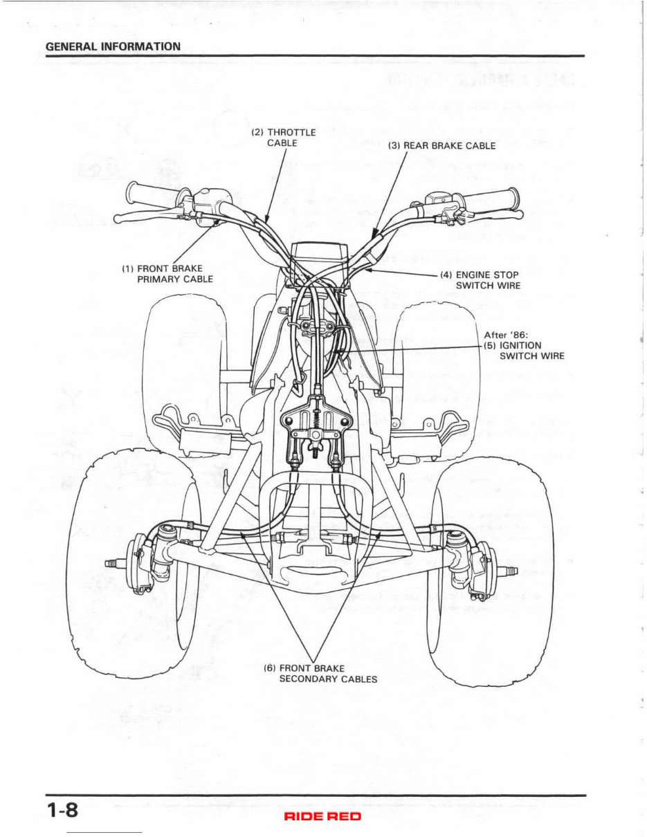
GENERAL INFORMATION 1-8 (1) FRONT BR',"E PRIMARY CABLE (2) THROTTLE (3) REAR BRAKE CABLE ~""'::"'---_"'4 ' ENGINE STOP SWITCH WIRE After '86: J ~I.-.l¥--J'-I------j (5) IGNITION It; SWITCH W IRE 16) FR()NT"BRAKE SECONDARY CABLES Downloaded from www.Manualslib.com manuals search engine
Get your hands on a comprehensive workshop service and repair manual for the 1986-1987 Honda TRX 70 Fourtrax ATV. This manual is an invaluable resource for both professional mechanics and DIY enthusiasts. It contains detailed information on maintenance, tune-up, repair, and overhaul procedures, accompanied by hundreds of original photographs and illustrations. The step-by-step instructions are designed to guide you through every job, making it suitable for first-time motorcycle repairers. The manual is printable, allowing you to have the necessary information at hand in your garage or workshop.
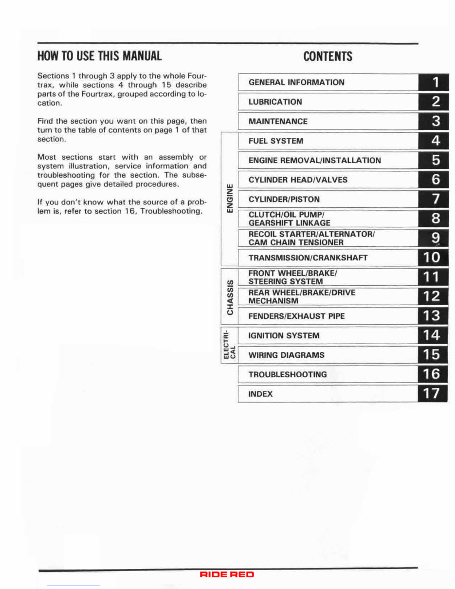
The manual covers a wide range of topics, including general information, lubrication, maintenance, fuel system, engine removal/installation, cylinder head/valves, clutch/oil pump/gearshift linkage, ignition system, and troubleshooting. It also includes wiring diagrams and an index for easy reference.
Product Details:
File Format: PDF
Printable: Yes, without any restriction
Delivery: A download link will appear on the checkout page after payment is complete
Requirements: Adobe Reader
By purchasing this service repair workshop manual, you can save on repair and maintenance costs. There's no need to pay for shipping or wait for an overpriced paper textbook to arrive via mail. Take advantage of the instant download option and save both time and money.
Don't hesitate any longer! Click on the green "Instant Download" button located at the upper left-hand corner of this page to complete all your repairs today and get full value for your money!

")