

Honda Trx400 EX 2006 Service Repair Manual
What's Included?
Fast Download Speeds
Online & Offline Access
Access PDF Contents & Bookmarks
Full Search Facility
Print one or all pages of your manual
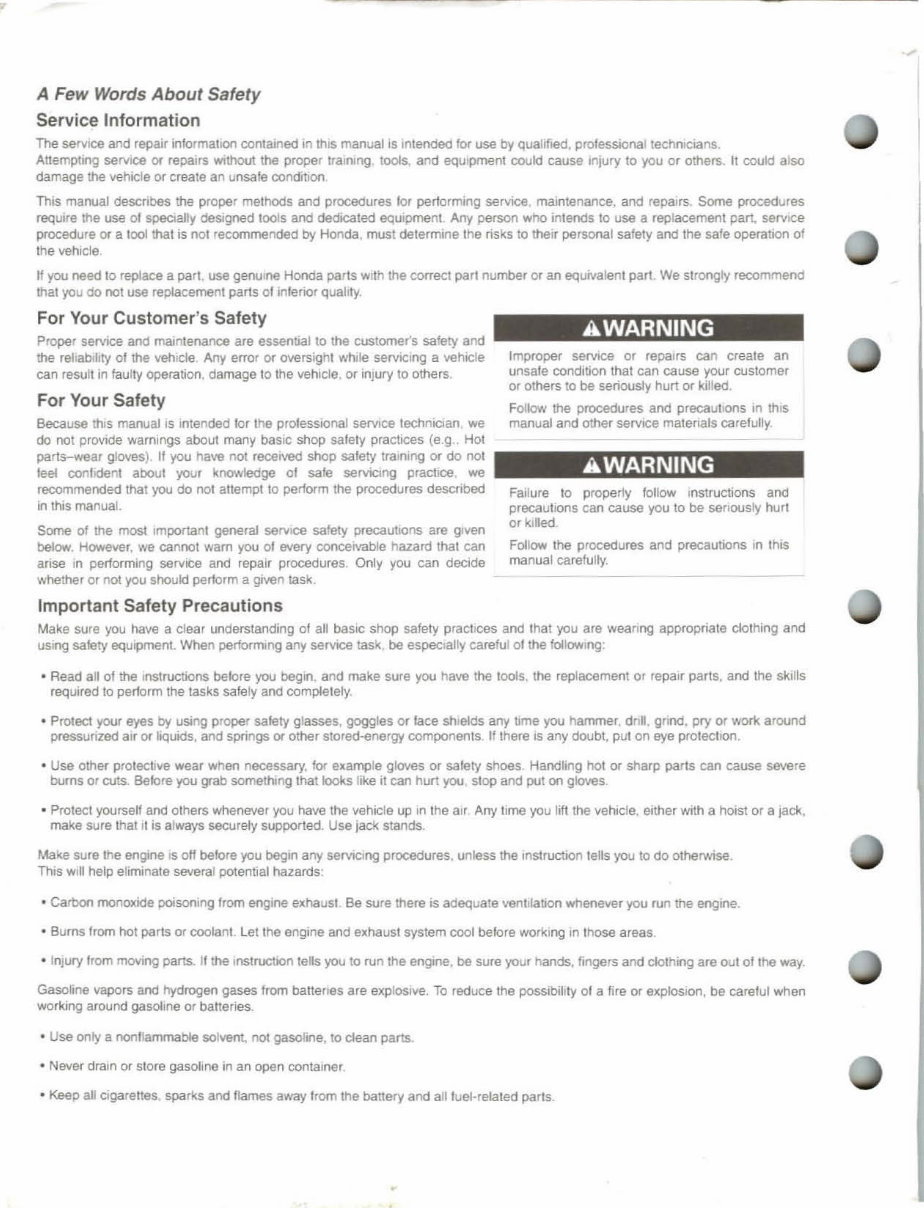
A Few Words About Safety
Service Information
The 5efV1ce and repair information contained In this manual IS Intended for use by qualified, professional technicians.
Attempting service Of repairs WIthout the proper training tools. and eqUIpment could cause Infury to you or others. It could also
damage the vehicle Of create an unsafe condition
This manual descnbes the proper methods and procedures lor performing servICe mamtenance, and repa.rs Some procedures
require the use 01 specially deSigned lOOIs and dedicated equipment Any person whO intends to use a replacement part, servICe
procedure or a loollhat is nol recommended by Hooda, must determine the nsks to their personal safety and the safe operatiOn of
the vehicle
If you need to replace a part use genuine Honda parts with lhe correct pari number or an equivalent part We strongly recommend
thai you do not use repiacement parts of infenor qualrty.
For Your Customer's Safety
Proper service and maintenance are essential to the customer's safety and
the reliability 01 the vehicle Any error or overSight while servicing a vehicle
can result in faulty operation, damage to the vehicle, or injUry to others.
For Your Safety
Because thiS manual IS Intended lor the professional selVlce technician we
do not provide warnings about many baSIC shop safety practices (e.g. Hot
parts-wear gloves). II you have nol received shop safety training or do I"IOt
JeeI oonloonl about your knowledge of safe servicing practice we
recommended thaI you do nol attempt to perform the procedures described
., this manual.
Some of the most Important general sen/Ice safety precautIOns are given
below. However, we cannot warn you of fNefY conceivable hazard that can
anse In performing sen/ICe and repair procedures Only you can decide
whether or not you should perform a given task.
Important Safety Precautions
AWARNING
Improper service or repaJrs can create an
unsafe condition that can cause your customer
or others to be seriously hurt or killed,
Follow the procedures and precavtK)(ls in thiS
manual and other selVlCe matenals carefully.
AWARNING
Failure 10 properly follow Instructions and
precautions can cause you to be senously hurt
or klled
Follow the procedures and precautiOns In 1t'IIS
manual carefully.
Make sure you have a clear understanding of all baSIC shop safety practJces and that you are weam"IQ appropriate clothing and
USing safety eqUipment, When performing any service task. be eSpE!C1ally careful 01 the follOWing'
• Read all of the Instructions belore you begin. and make sure you have the tools, the replacement or repair parIS, and the skills
reqUired to perform the tasks safety and completely.
• Protect your eyes by usmg proper salety glasses, goggles or lace shields any time you hammer. dnn. grind, pry or work around
pressurized air or liquids, and springs or other stored-energy componeols If there IS any doubt, pul on eye proteCllon.
• Use other protective wear wheo necessary. for example gloves or salety shoes. Handling hot or sharp parts can cause severe
burns or cuts. Belore you grab somethmg lhat looks like it can hurt you stop and put on gloves
• Protect yourself and others whenever you have the vehicle up In the air Any time you lift the vehicle, enher with a hoist or a jack.
make sure that It is always securely supported. Use jack stands.
Make sure !he engine IS off helore you begin any serviclng procedures, unless the Inslruction tells you to do othefWIse
This win help eliminate several potential hazards:
• Carbon monOXIde poiSOning 'rom engine exhaust Be sure there is adequate venlliation whenever you run the engine.
• Burns from hot parIs or coolant. Let the engine and exhaust system cool belere working In those areas
• InjUry from moving pans. If the Instl1.JCOOn tells you to run the engine. be sure your hands. fingers and clothing are out ollhe way.
Gasoline vapors and hydrogeo gases from battenes are explOSive. To reduce the possibility 01 a lire or explOSion, be careful when
working around gasoline or batter;es
• Use only a nonflammable solvent, not gasolme. to clean parts.
• Never dram or Siore gasoline in an open container
• Keep all Cigarettes. sparks and names away Irom the battery and ailluel'reiated parts .
•
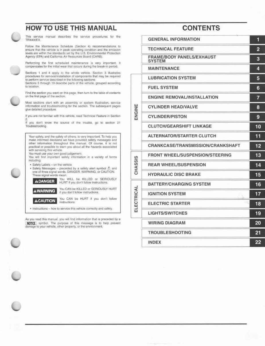
HOW TO USE THIS MANUAL
This servICe manual dllSCflOOs the service procadures klf !he
TAX400EX
Follow the Maintenance Schedule (Section 4) recommendations \0
ensure thai the vehicle is in pa~k optIrallng oorditron and the emlssioo
levels are within the slafldards set by the U,S. EnvIroomenlal Protection
AgencY (EPA) and Cali lorma Air Resources Board (CARS)
Perfon;niog the first Sd1eduled maintenaf10e is very importanl II
compensates kif the ;nilial wear lhat occurs during tile break·1n period.
Sections 1 and 4 aWy to tho whole vehtde SactKll1 3 lIIUS\rn,8S
procedures for removaVinSlal!a\lon of components that may be reqUIred
to perform S8fV1Ge dascrlbed In the IoIlow.og sectlOtlS.
Sections 5 through 19 deSCribe parts o l lllll vehiCle', groupo:!d sccordll"9
10 \oCa.tW)n.
Fmc! the section you warn on this page. then Mn to the table of contents
on the fifSI page altha section
Most sections sl art wtlh an assembly or system 1 II1I51ra6oo, service
IntJrma\lon afld trwbleshoolmg lor Ihe sectlOfl The subooquent pages
give detalilld procedure.
I!)IOU are not IamHiar with rhos vehicle, read Techrucal Fealure lfl 5edion
2.
It )IOU don1 knQw thl! source ot tha trouble, go to se<:tion 21
Troubleshooting
Your safety. aoo the safely of others. as very Imponan!. To help you
make Inbl'lned deasione we have pl'OYlded safety messages and
OItIer Infofmallon throughout \tIlS manual. 01 course, it Is 001
pl8CIical or possible 10 warn you aboul all th(l ha~ards associaled
wiItI serviCIng tIllS vehocla
'Ibu must use your 0WI'1 good Judgement
You wi" lind Hnp<l(tant safety InlormabOn ,n a variety 01 forms
including:
• Sa\Qty Labels - on tho vehtclo
• safety MtlS5aIl"'S - precWed by a safety alart symbol i and
one 01 !hroo signal words. DANGER. WARNING. or CAUTION.
These SlgNIt words mean:
"'-dna; ;1 ;:RTV:;I~ :n·IK~LL!Oi,:,U::~OUSLY
You CAN De KILLED or SERIOUSLY HURT
m'i1;luw, l tI ,I you donllollow instrucOOns.
mijijU.iU ~~~S~ HURT ~ you don·t follow
• Instructions - how to sern;e thiS ~6'hicle correctly and salely.
As you read ItIIS manual. you WIll flna lnlomlallOfl !ha! is preceded by a
[I()1'JC[l symbol The PUfpoie 01 this message is 10 htllp proven!
damage 10 your Y8I1lCla, oltler property, Or tho environment.
w
;!;
C>
z
w
-'
'"
()
a:
t;
w
-'
w
CONTENTS
GENERAL INFORMATION
TECHNICAL FEATURE
MAINTENANCE
LUBRICATION SYSTEM
FUEL SYSTEM
ENGINE REMOVAUINSTALLATION
CYLINDER HEADNALVE
CVLlNDERIPISTON
CLUTCH/GEARSHIFT LINKAGE
ALTERNATOR/STARTER CLUTCH
CRANKCASE/TRANSMISSION/CRANKSHAFT
FRONT WHEEUSUSPENSIONISTEERING
REAR WHEEUSUSPENSION
HYDRAULIC DISC BRAKE
BATTERY/CHARGING SYSTEM
IGNITION SYSTEM
ELECTRIC STARTER
LlGHTSlSWITCHES
WIRING DIAGRAM
TROUBLESHOOTING
INDEX
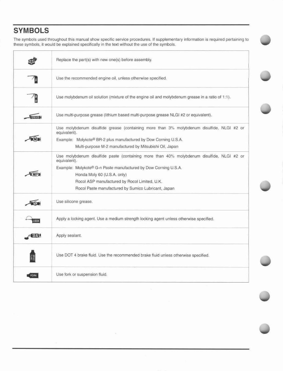
SYMBOLS
The symbols used throughout this manual show specific service procedures. If supplementary information is required pertaining to
these symbols, it would be explained specifically in the texl without the use of the symbols.
I!!I
Replace the part(s) with new one(s) before assembly.
---"l
Use the recommended engine oil, unless otherwise specified.
7J
Use molybdenum oil solution (mixture of the engine oil and molybdenum grease in a ratio of 1: 1).
• .s.;m;~
Use mUlti-purpose grease (lithium based mUlti-purpose grease NLGI #2 or equivalent).
Use molybdenum disulfide grease (containing more than 3% molybdenum disulfide, NLGI #2 or
equivalent).
~
Example: Molykote® BA -2 plus manufactured by Dow Corning U.SA
Multi-purpose M-2 manufactured by Milsubishi Oil, Japan
Use molybdenum disulfi de paste (containing more than 40% molybdenum disulfide, NLGI #2 or
equivalent).
Example: Molykote® G'n Paste manufactured by Dow Corning U.S.A.
AID Honda Moly 60 (U.S.A. only)
Roeol ASP manufactured by Roeol Limited, U.K.
Roeol Paste manufactured by Sumico Lubricant, Japan
..-'iSWI
Use silicone grease.
0,.
Apply a locking agent. Use a medium strength locking agent unless othelWise specified.
-
JGJIl
Apply sealant.
I
Use DOT 4 brake fluid. Use the recommended brake fluid unless othelWise specified.
GIl
Use fork or suspension fluid.
1. GENERAL INFORMATION
SERVICE RULES ··· .... ····································· 1-2
MODEL IDENTIFiCATION ······························ 1-2
GENERAL SPECiFiCATIONS ············· ·· ······· ·· · 1-5
LUBRICATION SYSTEM
SPECiFiCATIONS··········································· 1-7
FUEL SYSTEM SPECiFiCATIONS················· 1-7
CYLINDER HEAD/VALVE
SPECiFiCATIONS··········································· 1-7
CYLINDER/ PISTON SPECIFICATIONS ········· 1-8
CLUTCH/ GEARSHIFT LINKAGE
SPECiFiCATIONS··········································· 1-8
ALTERNATOR /STARTER CLUTCH
SPECiFiCATIONS········································ ... 1-8
CRANKCASE/ TRANSMISSION/ CRANKSHAFT
SPECiFiCATIONS··········································· 1-9
FRONT WHEEL /S USPENSION/STEERING
SPECiFiCATIONS··········································· 1-9
REAR WHEEl/SUSPENSION
SPECiFiCATIONS···· ······································1-10
HYDRAULIC DISC BRAKE
SPECiFiCATIONS········ ··· ·· ······· ·· ·· ··· ·· ····· ··· ·· ··· 1-10
BATTERY/ CHARGING SYSTEM
SPECiFiCATIONS·········································· 1·10
IGNITION SYSTEM SPECIFICATIONS ········ 1-10
ELECTRIC STARTER SPECIFICATIONS ······ 1-10
LIGHTS/SWITCHES SPECIFICATIONS ······· 1-11
STANDARD TORQUE VALUES ··················· 1-12
ENGINE & FRAME TQRQUE VALUES ··· ····· 1-12
LUBRICATION & SEAL POINTS ··········· ·· ····· 1-16
CABLE & HARNESS ROUTING ··················· 1-18
EMISSION CONTROL SYSTEMS ················ 1-28
1-1
GENERAL INFORMATION
SERVICE RULES
1. Use genuine Honda or Honda-recommended pans and lubricants or their equivalents. Pans that do not meet Honda's
design specifications may cause damage to the vehicle.
2. Use the special tools designed for this product to avoid damage end incorrect assembl y.
3. Use only metric tools when servicing the vehicle. Metric bolts, nuts and screws are not interchangeable with English
fasteners .
4. Install new gaskets, O-rings, cotter pins. and lock plates when reassembling.
5. When tightening bolts or nuts, begin with the larger diameter or inner bolt first. Then tighten to the specified torque
diagonally in incremental steps unless 8 particular sequence is specified.
6. Clean parts in cleaning solvenl upon disassembly. Lubricate any sliding surfaces before reassembly.
7. After reassembly, check all parts for proper installation and operation.
8. Route all electrical wires as shown in the Cable and Harness Routing (page 1-18).
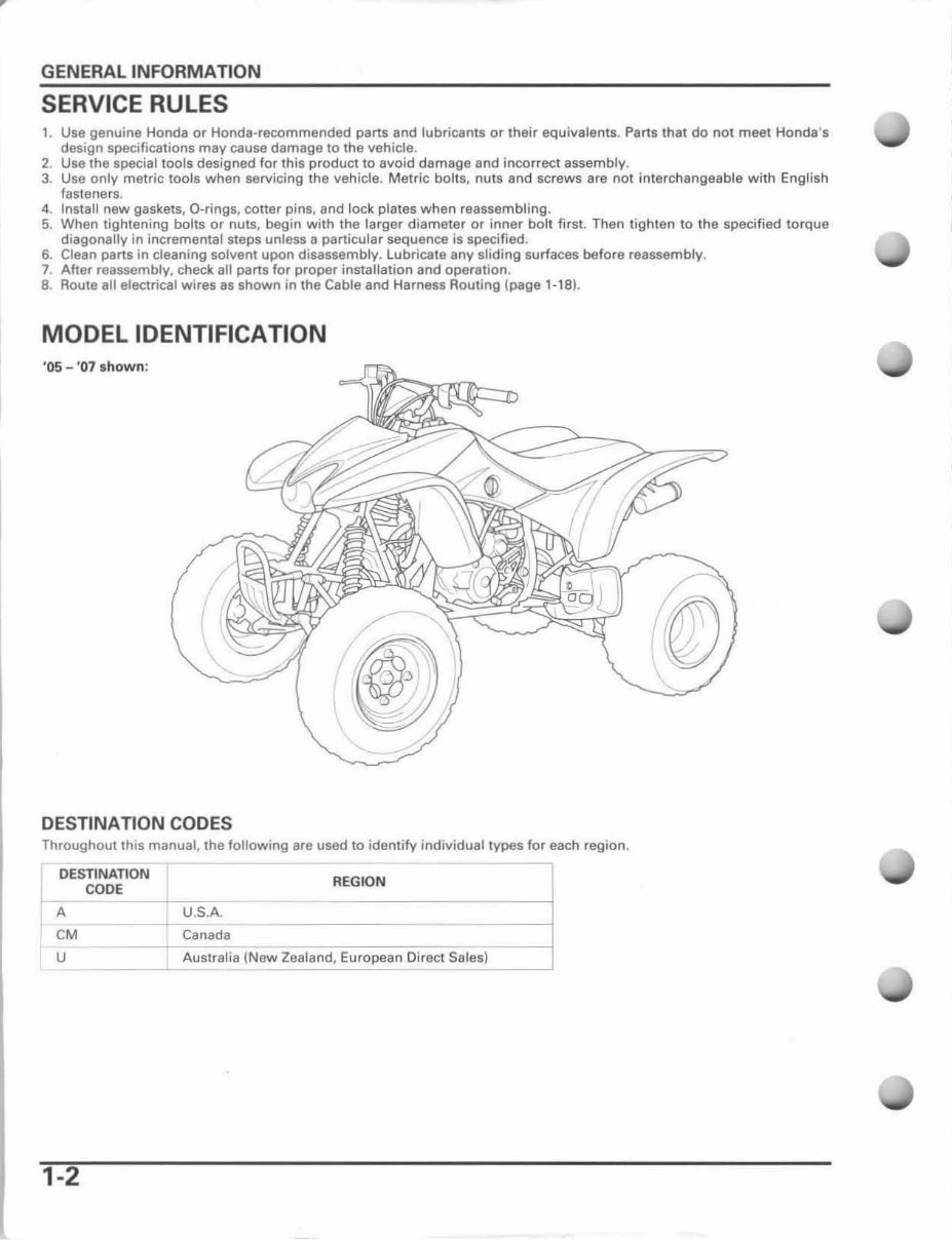
MODEL IDENTIFICATION
'05 - ' 07 sho wn :
DESTINATION CODES
Throughoullhis manual. the following are used to identify individual types for each region.
DESTINATION
CODE
U.S.A.
Canada
REG ION
A
eM
u Australia (New Zealand, European Direct Sales)
---'----
1-2
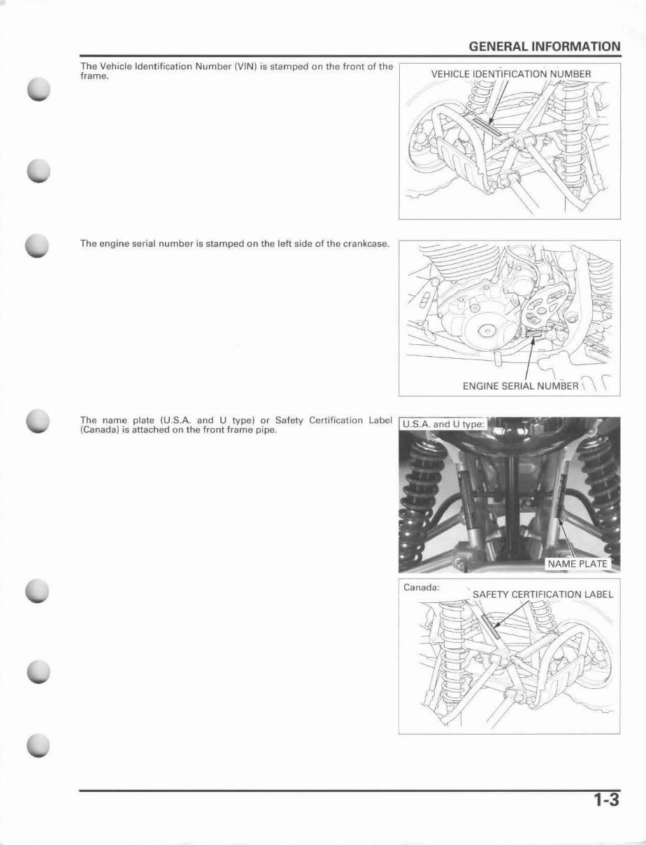
The Vehicle Identification Number (VI N) is stamped on the front of the
frame.
The engine serial number is stamped on the left side of the crankcase.
The name plate (U.S.A. and U type) or Safety Certification Label
(Ca nada) is attached on the front frame pipe.
GENERAL INFORMATION
VEHICLE IDENTIFICATION NUMBER
~~t ~
ENGINE SERIAL NUMBER \\ \
Canada:
"--.,.,,,,~ S 'i AFETY CERTIFICATION LABEL
1-3
GENERAL INFORMATION
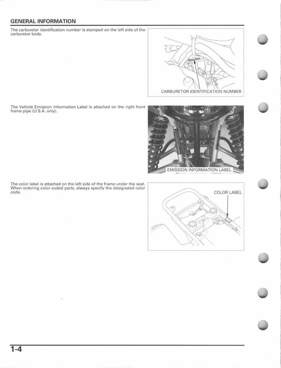
The carburetor identification number is stamped on the left side of the
carburetor body.
The Vehicle Emission Information Label is attached on the right front
frame pipe (U.S.A. only).
CARBURETOR IDENTIFICATION NUMBER
The color label is attached on the left side of the frame under the seat. ,------------------,
When ordering color coded parts, always specify the designated color
code. COLOR LABEL
1-4
GENERAL INFORMATION
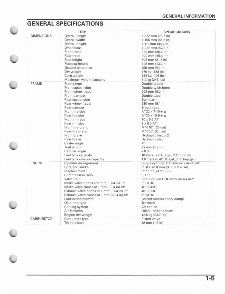
GENERAL SPECIFICATIONS
I DIMENSIONS
ITEM
Overali length
Overall width
Overall height
Wheelbase
Front tread
Rear tread
Seat height
Footpeg height
Ground clearance
Dry weight
Curb weight
SPECIFICATIONS
1,822 mm ( 71.7 in)
1. 155mm (45.5 inJ
1,111 mm (43 .7 in)
1.217 mm (47.9 in)
920 mm (36.2 in)
900 mm (35.4 in)
80B mm (3 1.8 in)
348 mm (13.7in)
105 mm (4.1 in)
176 kg (388lbs)
184 kg (406lbs)
r FRAME
__ --I-I M2C'x :=imum weight capacity
Frame type
__ -,-- ,110 kg (243 Ibs)
Double cradle
Double wish -bone
209 mm (8.2 in)
Double tube
Swingarm
ENGINE
Front suspensi on
Front wheellravel
Front damper
Rear suspension
Rear wheellravel
Rea r damper
Front tire size
Rear lire size
Front rim size
Rear rim size
Front lire brand
Rear tire brand
Front brake
Rear brake
Caster angle
Trail length
Camber angle
Fuel tank capacity
Fuel tank reserve capacity
Cylinder arrangement
Bore and stroke
Displacement
Compression ratio
Valve train
Intake valve opens at 1 mm (0.04 in) 11ft
Intake valve doses al 1 mm (0.04 in) lift
Exhaust valve opens at 1 mm (0.04 in) lift
EKhaust valve closes at , mm (0.04 in) lift
lubrication system
Oil pump type
Cooling system
Air filtration
230 mm (9.1 in )
Single tube
AT22 x 7-10 * *
AT20 x 10-9 .. *
IOx5.5AT
9x8.0AT
MIR 101 (Ohtsu)
MIR 501 (Ohtsu)
Hydraulic disc x 2
Hydraulic disc
r
32 mm (1 .3 in)
_ 0.8
D
10 liters (2.6 US gal, 2.2 Imp gal)
1.6 liters (0.42 US gal, 0.35 Imp gal)
Single cylinder. transversely installed
85.0 x 70.0 mm (3.35 x 2.76 in)
397 cm
3
(24 .2 cu-!n)
9.1 : 1
Chain driven OHC with rocker arm
5° BTDC
40° ABDC
40° BBDC
5<> ATDC
Forced pressure (dry sump)
Trochoid
Air cooled
Oiled urethane foam
CARBURETOR
Engine dry weight
Carburetor type
_ __ ,,4"'2."'5,, ' ''''9 (93.7 .lcb~'J~ _ __ _
Piston valve
~ _______ LT~h ~, -",onle bore 38 mm (1.5 in)
-
1-5
GENERAL INFORMATION
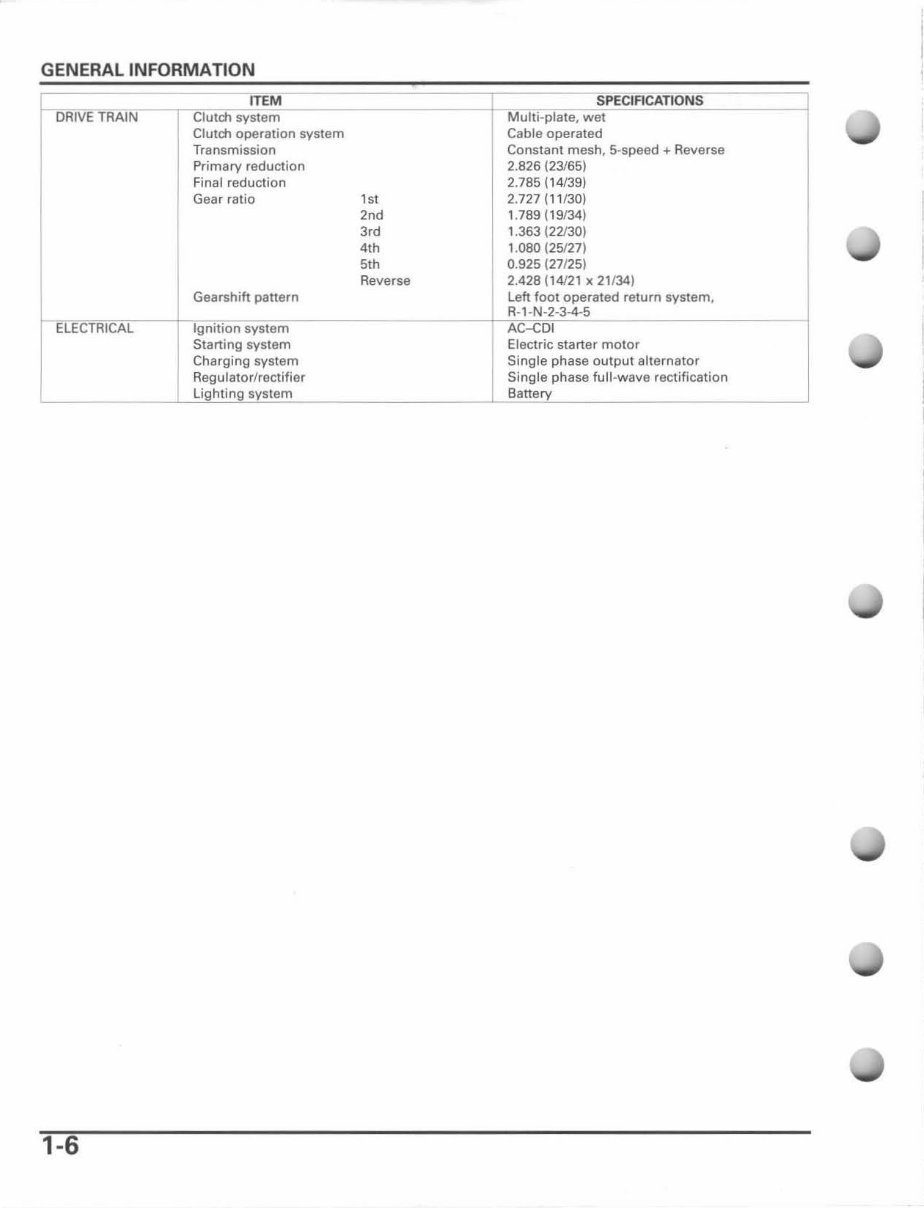
r---oruVE TRAIN
ITEM $PECIACATIONS
I
Clutch system Multi -plate, wet
Clutctl operation system Cable operated
Transmission Constant mesh, 5-speed ... Reverse
Primary reduction 2.826 (23/65)
Final reduction 2.785 (1 4/39)
Gear ratio
,,,
2.727 (11/30)
'od
1.789 (1 9134)
3,d 1.363 (22130)
4th 1. 080 (25127)
5th 0.925 (27/25)
Reverse 2.428 (14121 x 21134)
I ELECTRICAL
Gearshift panern Left fool operated rel urn system,
R-l-N-2-3-4-5
Ignition syst em AC-CDI
Starting system Electric starter motor
Charging system Single phase outpu t alternator
Regulator/rectifier Single phase full-wave rectification
, lighting system Banery
-
1-6
You're Reading a Preview
What's Included?
Fast Download Speeds
Online & Offline Access
Access PDF Contents & Bookmarks
Full Search Facility
Print one or all pages of your manual
$37.99
Viewed 74 Times Today


Secure transaction
What's Included?
Fast Download Speeds
Online & Offline Access
Access PDF Contents & Bookmarks
Full Search Facility
Print one or all pages of your manual
$37.99
This manual contains maintenance and repair procedures for the Honda Trx400 EX 2006. It is specifically written for both the do-it-yourselfer and the experienced mechanic. The manual provides step-by-step instructions based on the complete disassembly of the machine. It includes a level of detail, along with hundreds of photos and illustrations, to guide you through each service and repair procedure.
Manual Contents:
- General information
- Technical features
- Frame/body panels/exhaust system
- Maintenance
- Lubrication system
- Fuel system
- Engine removal/installation
- Cylinder head/valve
- Cylinder/piston
- Clutch/gearshift linkage
- Alternator/starter clutch
- Crankcase/transmission/crankshaft
- Front wheel/suspension/steering
- Rear wheel/suspension
- Hydraulic disc brake
- Battery/charging system
- Ignition system
- Electric starter
- Lights/switches
- Wiring diagram
- Troubleshooting
- Index
Additional Information:
- Language: English
- Printable: Yes
- File Format: PDF
- Compatibility: Windows and Mac
- Requirements: Adobe Reader


