

TRX250x service manual repair 1987-1988 TRX250x
What's Included?
Fast Download Speeds
Online & Offline Access
Access PDF Contents & Bookmarks
Full Search Facility
Print one or all pages of your manual
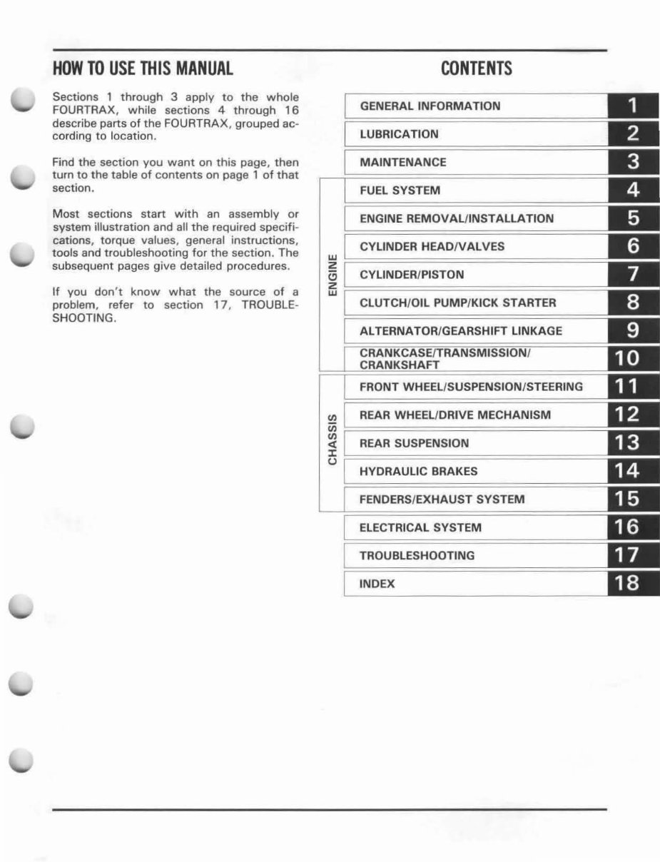
HOW TO USE THIS MANUAL
Sections 1 throug h 3 apply to the whole
FOU RTRAX, while sections 4 through 16
describe parts of the FOU RTR AX, grouped ac-
co rdin g to location.
Find the section you want on this page, then
turn to t he t able of contents on page 1 of that
section.
Mos t secti ons start with an assembly or
syst em ill ustration and alt the required specifi-
ca ti ons, to rque values, general inst ru ctions,
tools and troubleshooting for the section. The
subsequent pages give detailed procedures.
If you don't know what the source of a
problem, refer to section 17 . TR OUBLE-
SHOOTING .
CONTENTS
GENERAL INFORMATION
LUBRICATION
MAINTENANCE
FUEL SYSTEM
ENGINE REMOVAUINSTALLATION
CYliNDER HEAD/VALVES
~ ~============================
'"
CYliNDER/PISTON
~ ~============================
CLUTCH/OIL PUMP/KICK STARTER
ALTERNATOR/GEARSHIFT liNKAGE
FRONT WHEEL/SUSPENSION/STEERING
'" REAR WHEEU DRIVE MECHANISM
Cii :============= =
~ REAR SUSPENSION
n ~==========================
HYDRAUliC BRAKES
FENDERS /EXHAUST SYSTEM
ELECTRICAL SYSTEM
TROUBLESHOOTING
INDEX
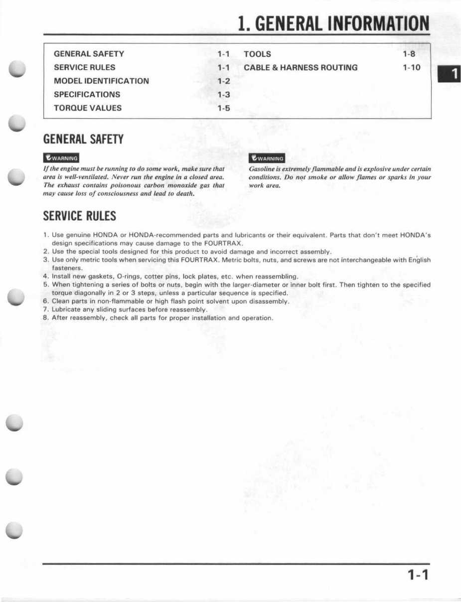
1. GENERAL INFORMATION
GENERAL SAFETY
SERVICE RULES
MODELIOENTIFICATION
SPECIFICATIONS
T ORQUE VALU ES
GENERAL SAFETY
; ii ,
,-,
,-,
' -2
' -3
' -5
TOOLS
CABLE & HARNESS ROUTING
It
' -8
'-'0
If the engine must be running to do some ", ork, make sure that
area Is well-ventilated. Never fIIn the engine in Q d osed area.
Th e exhaust contains poisonous carbon monoxide gas that
ma)' cause loss of consciousness and lead to death.
Gasoline is utremely flammable and; s ex pl osive u ndu urtain
conditions. Do "f!' smoke or 0/10 11' flames or sparks /n }'Our
work area.
SERVICE RULES
1. Use genuine HONDA or HONDA-recommended parts and lubricants or their equivalent. Parts that don 't meet HONDA 's
design specifications may cause damage to the FOURT RAX .
2 . Use the special tools deSigned for this product to avoid damage and incorrect assembly.
3. Use only metric tools when servicing this FOUATAAX . Metric bolts , nuts , and scr ews ara not i nterc hangeable with English
fasteners.
4 , InstaU new gaskets. O-rings, co tt er pins, lo ck. plates. etc. when reassembling.
5. When tightening a se ries o f bolts or nuts, begin w ith the larger-diamete r or inn er bolt first. Then tighte n to the specified
torq ue diagonally in 2 or 3 steps, unless a pa rt icular sequence is specified.
6. Clean parts in non-flammable or high flash point solvent upon disassembly.
7. Lubricate any sliding surfaces bef ore reassembly.
8. Afte r reassembly, check all parts for proper installation and operation.
1-1
GENERAL INFORMATION
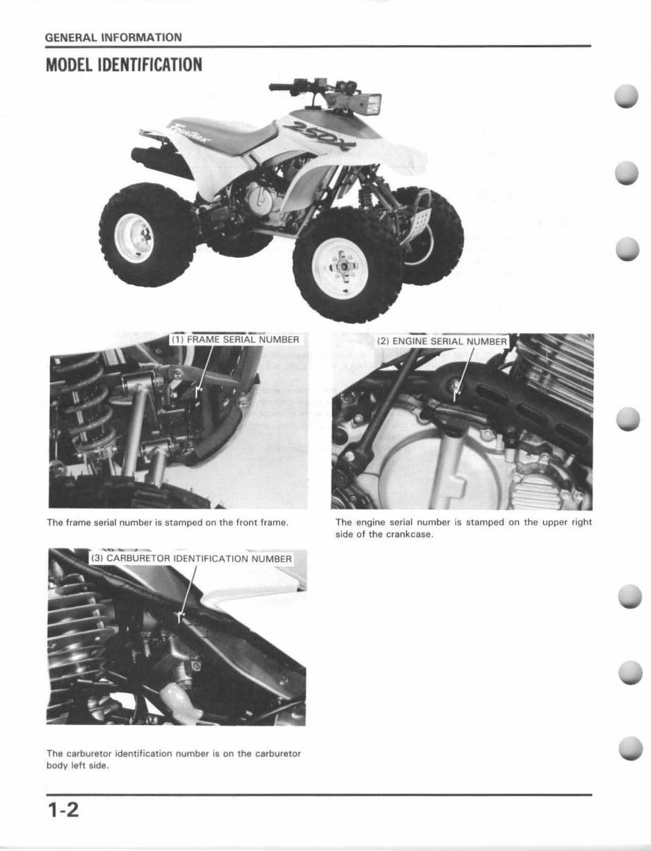
MODEl IDENTIFICATION
The frame serial number is stamped on the fr ont frame.
~
CARBURETOR IDENTIFICATION NUMBER
The carburetor identification number is on the carburetor
body left side.
1-2
The engine se r ia l number is stamped on the upper right
side of the crankcase.
GENERAL INFORMATION
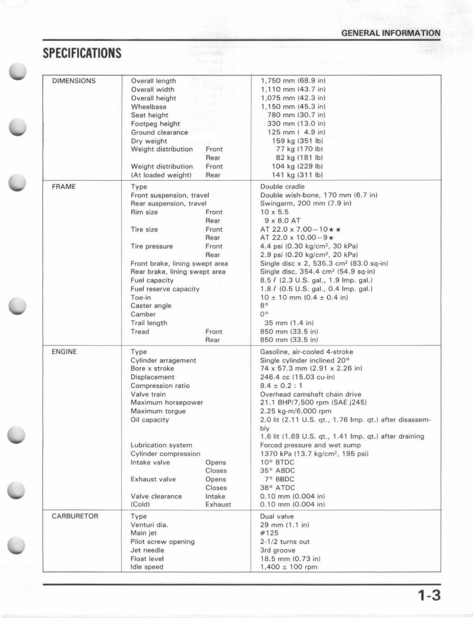
SPECIFICATIONS
OIMENSIONS Overall length 1,750 mm (68.9 in)
Overall width 1,110 mm (43.7 in)
Overall height 1 ,075 mm (42.3 in)
Wheelbase 1,150 mm 145.3 in)
Seat height 780 mm (30.7 in)
Footpeg height 330 mm (13.0 in)
Ground clearance 125 mm ( 4.9 in)
Dry weight 159 kg (351 fbi
Weight distribution Front 77 kg (1 70 fb i
Rear 82 kg (181 fbi
Weight distribution Front 104 kg (229 fbi
(At loaded weight) Rear 141 kg(311Ib)
FRAME Type Double cradle
Front suspension, travel Double wish-bone, 170 mm (6.7 in)
Rear suspension, travel Swingarm, 200 mm 17.9 in)
Rim size Front 10 x 5.5
Rear 9 x 8.0 AT
Tire size Front AT 22.0 x 7.00 - 10 . *
Rear AT 22.0 x 10.00- 9.
Tira pressure Front 4.4 psi (0.30 kg/ cm
2
, 30 kPa)
Rear 2.9 psi (0.20 kg/ cm
2
, 20 kPa)
Front brake, lining swept area Single disc x 2, 535.3 cm
1
(83.0 sq-in)
Rear brake, lining swept area Single disc, 354.4 cm
1
(54.9 sq-in)
Fuel capacity 8.5' 12.3 U.S. gal., 1.9 Imp. gal.)
Fuel reserve capacity 1.8 f (0.5 U. S. gal., 0.4 Imp. gaL)
Toe-in 10 ± 10 mm (0.4 ± 0.4 in)
Caster angle 8"
Camber 0"
Trail length 35 mm 11.4 in)
Tread Front 850 mm (33 .5 in)
Rear 850 mm (33.5 in )
ENGINE Type Gasoline, air-cooled 4· slroke
Cylinder arragement Single cylinder inclined 20
0
Bore x stroke 74 x 57.3 mm (2.91 x 2. 26 in)
Displacement 246.4 cc (15.03 cu-in)
Compression ratio 9.4 ± 0.2 : 1
Va lve Irain Overhead camshaft chain drive
Maximum horsepower 21 .1 BHP/7 ,500 rpm (SAE j245)
Maximum torgue 2.25 kg·m/6, OOO rpm
Oil capacity 2.0 IiI (2. 11 U .S. qt ., 1. 76 Imp. qt.) after disassem-
bly
1 .6 IiI (1.69 U.S. qt ., 1.41 Imp. qt.) after draining
lubrication system Forced pressure and wet sump
Cylinder compression 1370 kPa (13.7 kg l cm
2
, 195 psi)
Intake valve Opens 10
0
BTDC
Closes 35
0
ABDC
Exhaust valve Opens 7
0
BBDC
Closes 38
0
ATDC
Va lve clearance Intake 0.10 mm (0.004 in)
(Cold) Exhaust 0.10 mm (0.004 in)
CARBURETOR Type Dual valve
Venturi dia. 29 mm 11.1 in)
Main jet #125
Pilot screw opening 2-1/2 turns out
Jet needle 3rd groove
Float level 18.5 mm (0.73 in)
Idle speed 1 ,400 ± 100 rpm
1-3
GENERAL INFORMATION
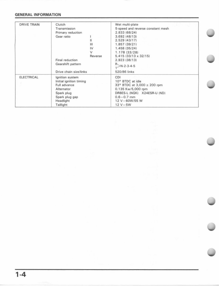
DRIVE TRAIN Clutch Wet multi-plate
Transmission 5-speed and reverse constant mesh
Primary reduction 2.833 (68124)
Gear rat io
,
3.692 (48/13)
II 2.529143/17)
"'
1.857139/21)
'V
1.458 (35/2 4)
V , . 178 (33/ 28)
Reverse 5.415 (33/13 x 32/15)
Final reduction 2.923 (38/13)
Gearshift pattern R
> N- 2-3-4-5
1
Drive chain sizellinks 520 /86 links
ELECTRICAL Ignition system CO,
Initial ignition timing 10
0
BTDC at idle
Full advance 33° BTDC at 3,000 j: 200 rpm
Alternator 0.' 35 Kw/5,OOO rpm
Spark plug DRBES-l (NGK) X24ESR-U INO)
Spark plug gap 0.6 - 0.7 mm
Headlight 12 V- SOW/ 55 W
Taillight 12 V - 5W
1·4
GENERAL INFORMATION
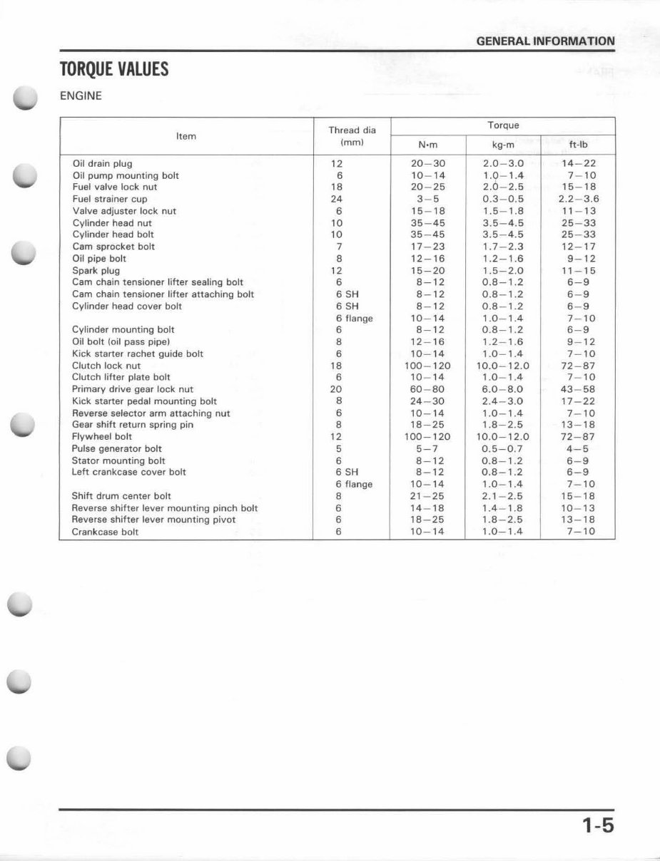
TORQUE VALUES
ENGINE
Thread dia
Torque
Item
( mm)
N·m kg -m ft-lb
Oil drain plug 12 20 - 30 2.0- 3.0 14 - 22
Oil pump mounting bolt 6 10 - 14 1.9- 1.4 7- 10
Fuel valve lock nut 18 20 - 25 2.0 - 2.5 15 - 18
Fuel strainer cup 24 3- 5 0.3-0 .5 2. 2-3.6
Valve adjuster lock nut 6 15 - 18 1.5- 1.8 11 - 1 3
Cyl inder head nut 10 35 - 45 3.5- 4.5 25 - 33
Cylinder head bolt 10 35-45 3.5-4.5 25-33
Cam sprocket bolt 7 17- 23 , .7 - 2.3 12 - 1 7
Oil pipe bolt 8 12 - 16 1.2 - 1.6 9- 12
Spark plug 12 15 - 20 1.5- 2.0 11 - 1 5
Cam chain tensioner lifter sealing bolt 6 8- 12 0.8 - 1.2 6- 9
Cam chain tensioner lifter attach ing bolt 6 SH 8- 12 0.8 - 1.2 6- 9
Cylinder head cove r bolt 6 SH 8- 12 0.8 - 1.2 6- 9
6 flange 10 - 14 1.0 - 1.4 7- 10
Cylinder mounting bolt 6 8- 12 0.8- 1.2 6- 9
Oil bolt (oil pass pipe) 8 , 2 - 16 1.2 - 1.6 9- 12
Kick starter rachet guide bolt 6 10 - 14 1.0 - 1.4 7- 10
Clutch lock nut 18 100 - 120 10.0 - 12.0 72 - 87
Clutch l ifter plate bolt 6 10- 14 1.0- 1.4 7- 10
Primary drive gear lock nut 20 60 - 80 6.0- 8.0 43 - 58
Kick starter pedal mounting bolt 8 24 - 30 2.4 - 3.0 17 - 22
Reverse selector arm attaching nut 6 10 - 14 1.0- 1.4 7- 10
Gear shift return spring pin 8 18-25 1.8-2 .5 13 - 18
Flywheel bolt 12 100 - 120 10.0- 12 .0 72- 87
Pulse generator bolt 5 5- 7 0.5- 0.7 4- 5
Stator mounting bolt 6 8- 12 0.8 - 1.2 6- 9
Left crankcase cover bolt 6 SH 8- 12 0.8 - 1.2 6- 9
6 flange 10 - 14 1.0 - 1.4 7- 10
Shift drum center bolt 8 21 - 25 2. 1- 2.5 15 - 18
Reverse shifter lever mounting pinch bolt 6 14- 18 1.4 - 1.8 10 - 13
Reverse shifter lever mounting pivot 6 18- 25 1.8 - 2.5 13 - 18
Crankcase bolt 6 10 - 14 1.0 - 1.4 7- 10
1-5
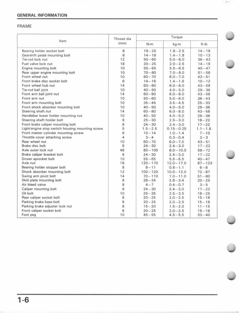
GENERAL INFORMATION
FRAME
Thread die
Torque
It em
(mm)
N·m kg -m It · lb
Bearing holder socket bolt 8 19 - 25 1.9 - 2.5 14 - 18
Gearshift pedal mounting bolt 6 14 - 18 1.4 - 1.8 10 - 13
Tie-rod lock nut 12 50 - 60 5.0 - 6.0 36 - 43
Fuel valve lock nut 18 20 - 25 2.0 - 2.5 14 - 18
Engine mounting bolt 10 55 - 65 5.5- 6.5 40 - 47
Rear upper engine mounting bolt 10 70 - 80 7.0- 8.0 51 - 58
Front wheel nut 10 60 - 70 6.0- 7.0 43 - 51
Front brake disc socket bolt 6 14 - 16 1.4 - 1.6 10- 12
Front wheel hub nut 14 60 - 80 6.0- 8.0 43 - 58
Tie-rod bait joint 10 40 - 50 4.0- 5.0 29 - 36
Front arm ball joint nut 14 60 - 80 6.0 - 8.0 43 - 58
Front arm nut 10 50 - 60 5.0- 6.0 36 - 43
Front arm mounting bolt 10 35 - 45 3.5- 4.5 25 - 33
Front shock absorber mounting bolt 10 40 - 50 4.0-5.0 29 - 36
Steering shah nut 14 60 - 80 6.0- 8.0 43 - 58
Handlebar lower holder mounting nut 10 40 - 50 4.0 - 5.0 29 - 36
Steering shaft holder bolt 8 25 - '30 2.5 - 3.0 18 - 22
Front brake caliper mounting bolt 8 24 - 30 2.4 - 3.0 17 - 22
light/engine stop switch housing mounting screw 5 1.5 - 2.5 0. 15 - 0. 25 1.1 - 1.8
Front master cylinder mounting screw 6 10 - 14 1.0- 1.4 7- 10
Throttle cover attaching screw 4 3- 4 0.3 - 0.4 2- 3
Rear wheel nut 10 60 - 70 6.0-7 .0 43 - 51
Brake disc bolt 8 24 - 30 2.4 - 3.0 17 - 22
Axle outer lock nut 48 80 - 100 8.0- 10.0 58 -72
Brake caliper bracket bolt 8 24 - 30 2.4 - 3.0 17 - 22
Driven sprocket bolt 10 55 - 65 5.5 - 6.5 40 - 47
Axle nut 18 120 - 170 12.0- 17.0 87 - 123
Bearing holder stopper bolt 8 8- 11 0.8- 1.1 6- 8
Shock absorber mounting bolt 12 100- 120 10.0 - 12 .0 72 - 87
Swing arm pivot bolt 14 70 - 110 7.0 - 11.0 51 - 80
Skid plate mounting bolt 8 28 - 34 2.8- 3.4 20 - 25
Air bleed valve 8 4- 7 0.4 - 0.7 3- 5
Caliper mounting bolt 8 24 - 30 2.4 - 3.0 17 - 22
Oil bolt 10 25 - 35 2.5 - 3.5 18 - 25
Rear caliper socket bolt 8 20 - 25 2.0 - 2.5 15 - 18
Parking brake base bolt 8 20 - 25 2.0 - 2.5 15 - 18
Parking brake adjuster lock nut 8 15 - 20 1 .5 - 2.0 11 - 1 5
Front caliper socket bolt 8 20 - 25 2.0 - 2.5 15-18
Foot peg 10 45-55 4.5- 5.5 33 - 40
1-6
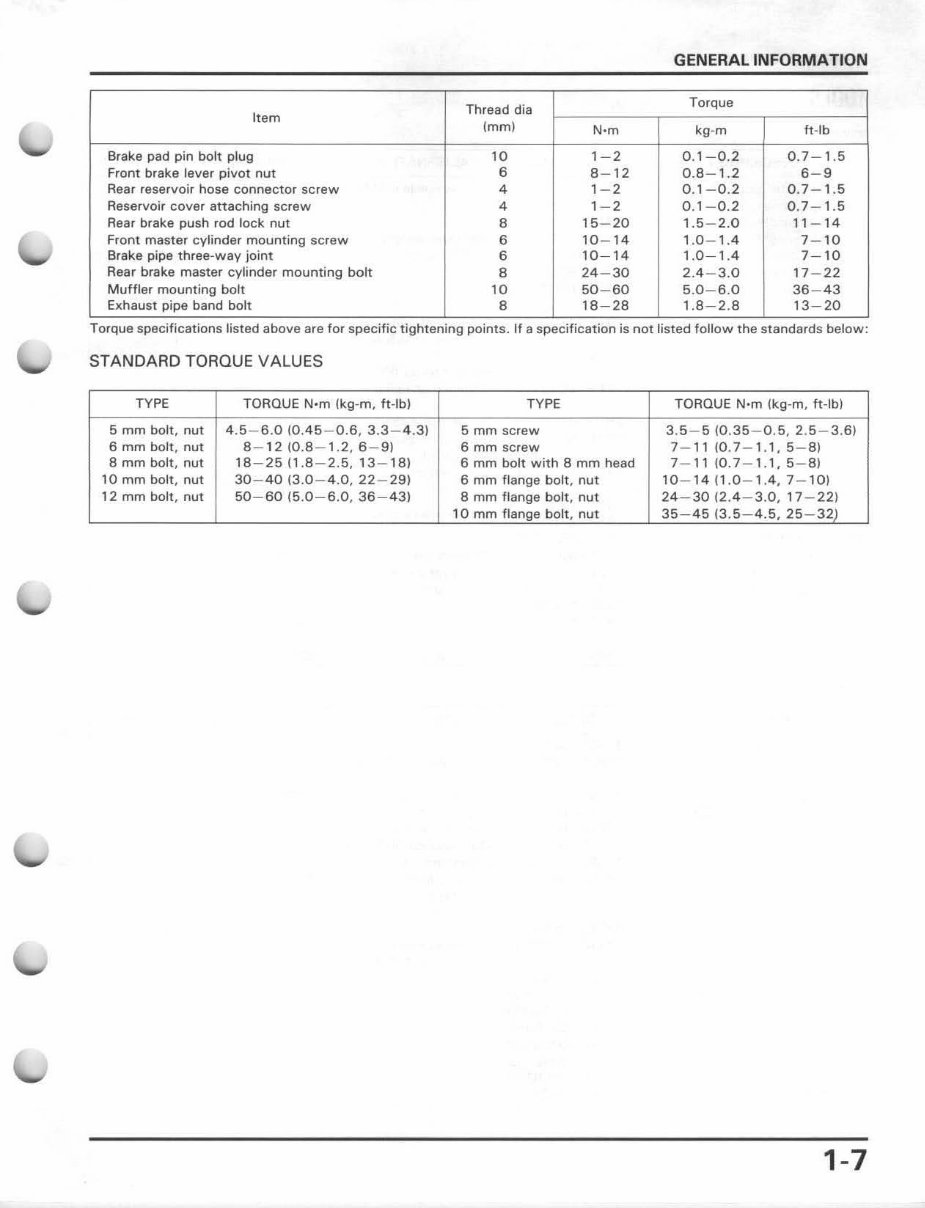
GENERAL INFORMATION
Thread dia
Torque
Item
(mm)
N·m kg -m fl -I b
Brake pad pin bolt plug 10 1- 2 0.1- 0.2 0.7 - 1.5
Front brake lever pivot nut 6 8- 12 0.8 - 1.2 6- 9
Rear reservoir hose connector screw 4 1- 2 0.1- 0.2 0.7- 1.5
Reservoir cover attaching scr ew 4 1- 2 0.1 - 0.2 0.7 - 1.5
Rear brake push rod lock nut 8 15 - 20 1.5 - 2.0 11 - 14
Front master cylinder mounting screw 6 10 - 14 1.0-1.4 7-10
Br ake pipe three-way joint 6 10-14 1 ,0-1.4 7-10
Rear brake master cylinder mounting bolt 8 24 - 30 2.4 - 3.0 17- 22
Muffler mounting bolt 10 50 - 60 5.0 - 6.0 36 - 43
Exhaust pipe band bolt 8 18 - 28 , .8 - 2.8 13- 20
.. ..
Torque specifications listed above are for specIfic tightening pomts. If a specification IS not listed follow the standards below:
STANDARD TORQUE VA LUES
TYPE TORQUE N· m {kg-m, ft·lbl TYPE TORQUE N'm (kg-m, ft-lbJ
5 mm bolt , nut 4.5-6 .0 (0.45-0.6, 3.3 -4 .31 5 mm screw 3.5- 5 (0.35 - 0.5, 2.5- 3.6)
6 mm bolt, nut 8-12 (0.8-1.2, 6-9) 6 mm screw 7- 1110 .7-1.1,5 - 81
8 mm bolt, nut 18 - 25 ( 1.8 - 2.5,13 - 181 6 mm bolt with 8 mm head 7- 11 (0.7 - 1.1, 5- 81
10 mm bolt, nut 30 - 40 (3.0 - 4.0, 22 - 291 6 mm flange bolt , nut 10-1411.0-1.4,7 - 101
12 mm bolt , nut 50 - 60 (5.0-6.0, 36-431 8 mm flange bolt, nut 24 - 30 (2.4 - 3.0, 17 - 221
10 mm flange bolt , nut 35 - 45 (3.5 - 4.5, 25 - 32)
1-7
You're Reading a Preview
What's Included?
Fast Download Speeds
Online & Offline Access
Access PDF Contents & Bookmarks
Full Search Facility
Print one or all pages of your manual
$31.99
Viewed 99 Times Today


Secure transaction
What's Included?
Fast Download Speeds
Online & Offline Access
Access PDF Contents & Bookmarks
Full Search Facility
Print one or all pages of your manual
$31.99
Get your hands on the comprehensive repair manual for the 1987-1988 Honda TRX 250x ATV. This manual covers everything from complete tear down and rebuild to detailed pictures and part diagrams, torque specs, maintenance, troubleshooting, and more. With 229 pages, it provides extensive information for professional mechanics and DIY enthusiasts alike.
This manual features clickable chapters and is searchable, allowing you to easily locate the information you need. There are no restrictions on printing or saving/burning to disc, providing you with convenient access to the manual.


