2009-2015 Honda Big Red MUV700 Service & Repair Manual
What's Included?
Lifetime Access
Fast Download Speeds
Online & Offline Access
Access PDF Contents & Bookmarks
Full Search Facility
Print one or all pages of your manual
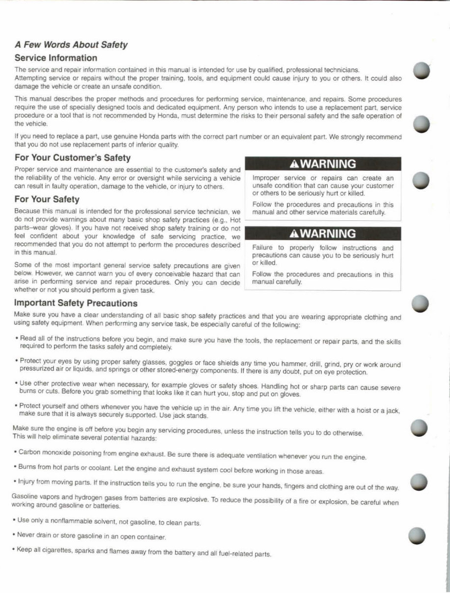
A Few Words About Safety Service Information The Service and repair Information contained In this manual IS intended for use by qualified. professional technicians. Attempting servICe or repairs without the proper training. 1000s, and equipment couk! cause injury 10 you or others. It could also damage the vehICle or create an unsafe oondltlon. This manual describes the proper methods and procedures for per10rmlng service, maintenance, and repairs. Some procedures reqUIre the use of specialty designed too ls and dedicated equipmenl. Any persoo who inleocis 10 use a replacement part, service procedure or a 1001 that is not recommended by Honda, must determine the risks 10 their persooaJ salery and the safe operatJon of the vehicle. II you need to re~ce a part, use genuine Honda parts with the correct pari number or an equivalent part. We strongly recommend that you do nol use replacement parts 01 I nferIOr qua lity. For Your Customer's Safety Proper service and maintenance are essential to the customer's salety and the reliability of the vehicle. Any error or oversight while servicing a vehicle can result in faulty operation, damage to the vehicle, or injury to others . For Your Salety Because Ihis manual is intended lor the professional service techmcian, we do nol provide warnings about many baSIC shop safety practices (e.g., Hot parts-wear gloves) . II you have not received shop safety training or do not feel oonfident about your knowfedge 01 safe servicing practice. we recommended that you do !lOt attempt to pertorm the procedures described In thiS manual. Some 01 the most Important general service safety precautioos are given below. However, we cannot warn you of every conceivable hazard that can arise in pertormtng seMCe and repair procedures. Only you can decide whether or not you should perform a given task. Important Salety Precautions AWARNING Improper service or repairs can create an unsafe condition that can cause your customer or others to be seriously hurl or killed. Follow the procedures and precautions in thiS manual and other service materials carefully. AWARNING Failure to property Iollow Instructions and precautIOns can cause you to be seriously hurt or killed. Follow the procedures and precaulJons In thts manual carefully. Make sure you have a clear understanding 01 all basIC Shop safety practices and that you ate wearing appropriate clothing and uSlOg safety equipment When pertorming any Service task, be especially careful of the follOWing: • Read all of the Instructions before you begin, and make sure you have the tools, the replacement or repair parts, and the skIlls required to perform the tasks safely and completely. • Protect your eyes by using proper safety glasses, goggles or face shields any time you hammer , drill, grind, pry or work around pressurized alT or liqUids, and SPrings or other stored-energy components. If there is any doubt, put on eye protection. • Use olher protectIve wear when necessary, for exampJe gloves or safety shoes. Handling hot or sharp parts can cause severe burns or cuts. Belore you grab something lhat looks like it can hurt you. stop and put on gloves. • Protect yourself and others whene\ler you have the vehicle up in the air. Any time you liftlhe vehicle, either with a hOist or a jack, make sure thai it is always securely supported. Use Jack stands. Make sure the engine is off before you begIn any serVICing procedures, unless the instruction tells you 10 do otherwise. This WIll help eliminate several potentlaJ hazards: • Carbon monoXide poisoning from engine exhaust. Be sure there IS adequate ventilation whenever you run the engine. • Burns from hoc parts or coolant. let lhe engine and exhaust system cool betare working In those areas. • Injury from mOVIng pans. If the Instruction lells you to run the engine. be sure your hands, fingers and clothing are out of the way. Gasoline vapors and ~drogen gases from banenes are explosive. To reduce Ihe possibility of a fire or explosion, be careful when working around gasolme or banenes. • Use only a nonflammable solvent, not gasoline. to clean paris . • NeYer drain or store gasoline In an open container. 4 Keep all cigarenes. sparks and flames away from the banery and alilueJ.related parts.
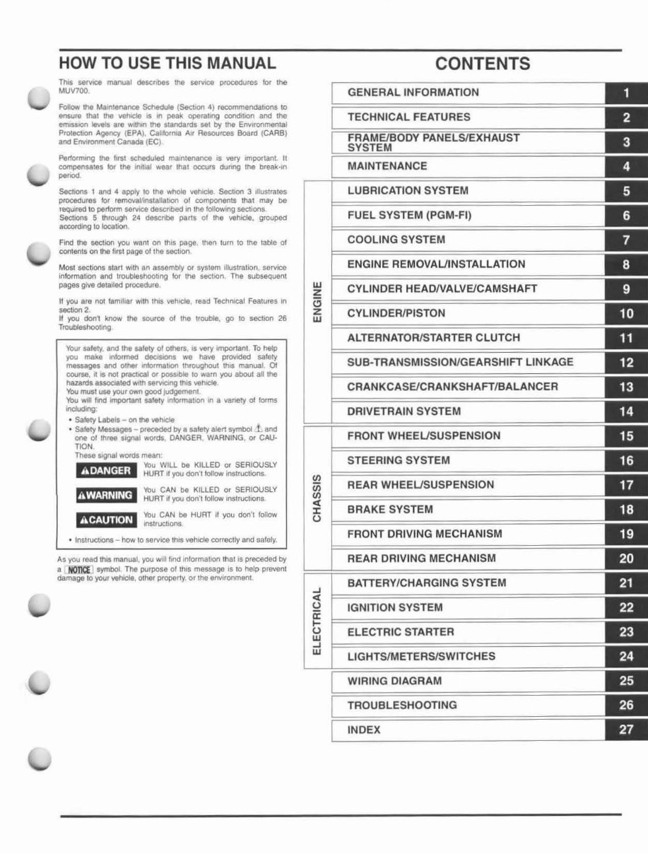
HOW TO USE THIS MANUAL Thrs 58MCe tnllflUl,l delCtlbes the WrY1C8 prooodu<es lor Ule MUV700, FoIow !he Ma.lOt_nee ~ tSeebon 4) recommendabOnS to _UI. that the \IehicI4I • In peak operating coodibon and the lIfI'IIS5on IlYels .,. WIIhIn tne standard. set tIy the EnYnonmenlal PtoIectJOn Agency (EPA). CaliIc:lN'4 AIr Resources Boord (CARB) Ind EfMroomenI ~ tEe) PertOlnung II\ei ',rsl SCheduled malOll1011nce IS WIry mportant. II compensates 10< the Wltbll w&ar lhat OCC\.Irs dunng me break ...... p.,," SeeIions 1 1M .. apply to tn. whole vehocIe Sec::tion 3 lIusrrates proc:«Iure, lor remO'alfinltalla1lofl ot cornpoo&nl$ thaI may De 'Bqllll\ld 10 pertorm MMce descnbed in tnelollowing sectionS s.ctioM 5 through 24 describe parts 01 II'Ie vehlde, grouped ac:cordklg to IocatlOl'l Find the &eet.an you want on thiS page, then lurn 10 the table 01 content. 00'\ the Hit' page oIllle secllOO Most sectiol'll star' With In 8$Sf1mb/y 04' system Illustration, sel\lice ifllormatlon Ind lroubles.hootlrlg lor the section. The SI.Ibseqll6nl pages give deta1led pl'oeedure ,t you .r. not lamMiar WIlli thiS vehICle read Tac/mlca' Features III seetiorI2. II you don' know 1h4t source 01 the llOUbie. go 10 sectlOI'I 26 Troubleshoolong '!'ou CAN be KILLED 0< SERIOUSLY mXWjI h! !h let! HURT II you cion', klIlow InsuUCllona. AS you read thlt manual, you woll r,nd ~ma\Jon ItIat Is preceded by • 1tOI1iCE symbOl. The purpose of In,. message IS to help pnMHlI damage to your Y&/lIeIe, 0I1lef property, or the 8f>Vlronmenl OJ Z '" Z OJ II> iii II> < :I: U -' < u ir .... frl -' OJ CONTENTS GENERAL INFORMATION TECHNICAL FEATURES MAINTENANCE LUBRICATION SYSTEM FUEL SYSTEM (PGM-FI) COOLING SYSTEM ENGINE REMOVALJINSTALLATION CYLINDER HEADNALVE/CAMSHAFT CYLINDER/PISTON ALTERNATOR/STARTER CLUTCH SUB-TRANSMISSION/GEARSHIFT LINKAGE CRANKCASE/CRANKSHAFT/BALANCER DRIVETRAIN SYSTEM FRONT WHEELJSUSPENSION STEERING SYSTEM REAR WHEELJSUSPENSION BRAKE SYSTEM FRONT DRIVING MECHANISM REAR DRIVING MECHANISM BATIERY/CHARGING SYSTEM IGNITION SYSTEM ELECTRIC STARTER LIGHTS/METERS/SWITCHES WIRING DIAGRAM TROUBLESHOOTING INDEX
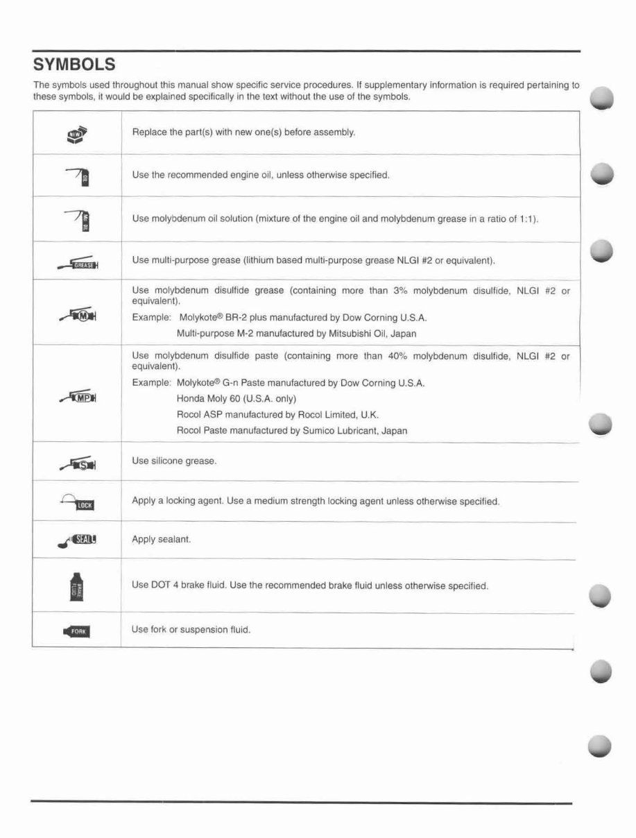
SYMBOLS The symbols used Ihroughoullhis manual show specific service procedures. If supplementary information is required pertaining to Ihese symbols, it would be explained specifically in the texl without the use of the symbols. !f;!~ .... I Replace the parl(s) with new one(5) before assembly. 'D Use the recommended engine oil , unless otherwise specified. - i 7J Use molybdenum oil solution (mixture of the engine oil and mOlybdenum grease in a ratio of 1: 1). ---- ~ u;;.. I Use multi-purpose grease (lithium based multi-purpose grease NlGI #2 or equivalent). -- , Use molybdenum disulfide grease (containing more than 3% molybdenum disulfide, NLGI #2 or equivalent). ~ Example: Molykole® BR·2 plus manufactured by Dow Corning U.S.A. Mutti-purpose M-2 manulactured by Mitsubishi Oil, Japan Use molybdenum disulfide paste (containing more than 40% molybdenum disulfide, NLGI 112 or equivalent). Example: Molykot~ G-n Paste manufactured by Dow Corning U.S.A. ~ Honda Moty 60 (U.S.A. only) Rocol ASP manufactured by Aocol Umited, U.K. Aocol Paste manufactured by Sumico Lubricant, Japan --- Use silicone grease. t1m:J Apply a locking agent. Use a medium strength locking agent unless otherwise specified, .,( ' 61ll Apply sealant. • Use DOT 4 brake fluid. Use the recommended brake fluid unless otherwise specitied. GIl I Use fork or suspension ftuid.
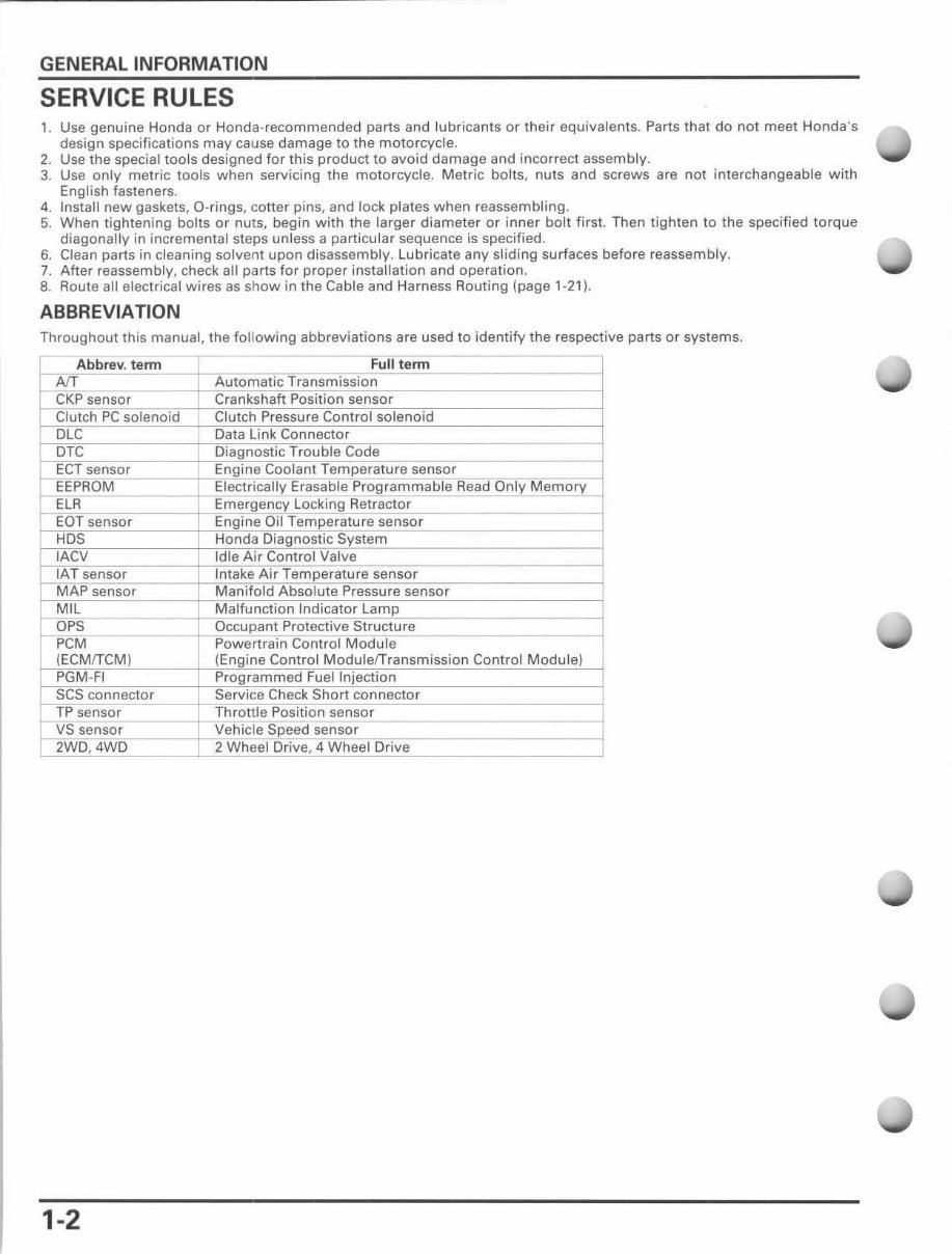
GENERAL INFORMATION SERVICE RULES 1. Use genuine Honda or Honda-recommended parts and lubricants or their equivalents. Parts that do not meet Honda's design specifications may cause damage to the motorcycle. 2. Use the special tools designed for this product to avoid damage and incorrect assembly. 3. Use only metric tools when servicing the motorcycle. Metric bolts, nuts and screws are not interchangeable with Engl i sh fasteners. 4. Install new gaskets, O-rings, cotter pins, and lock plates when reassembling. 5. When li ghtening bolts or nut s, begin with the larger diameter or inner bolt first. Then tighten to the specified torque diagonally in incremental steps unless a particular sequence is specified. 6. Clean parts in cleaning solvent upon disassembly. Lubricate any sliding surfaces before reassembly. 7. After reassembly, check all parts for proper installation and operation . 8. Route all electrical wires as show in the Cable and Harness Routing (page 1·21 ). ABBREVIATION Throughout this manual, the following abbreviations are used to identify the respective parts or systems. Abbrev. telTTl Full telTTl Af[ Automatic Transmission CKP sensor Crankshaft Position sensor Clutch PC solenoid Clutch Pressure Control solenoid I DLC Data Link Connector - DTC Diagnostic Trouble Code ECT sensor Engine Coolant Temperature sensor EEPROM , Electrically Erasable Programmable Read Only Memory _ ELR Emergency Locking Retractor EOT sensor Engine Oil Temperature sensor HDS Honda Diagnostic System . IACV Idle Air Control Valve ~;sensor Intake Air Temperature sensor MAP sensor Manifold Absolute Pressure sensor _ ~IL Malfunction Indicator Lamp DPS Occupant Protective Structure PCM Powertrain Control Module (ECMfTCM ) (Engine Control ModulefTransmission Control Module) PGM-Fl Programmed Fuel Injection SCS connector Service Check Short connector TP sensor Throttle Position sensor VS sensor Vehicle Speed sensor 2WD,4WD 2 Wheel Drive, 4 Wheel Drive 1-2
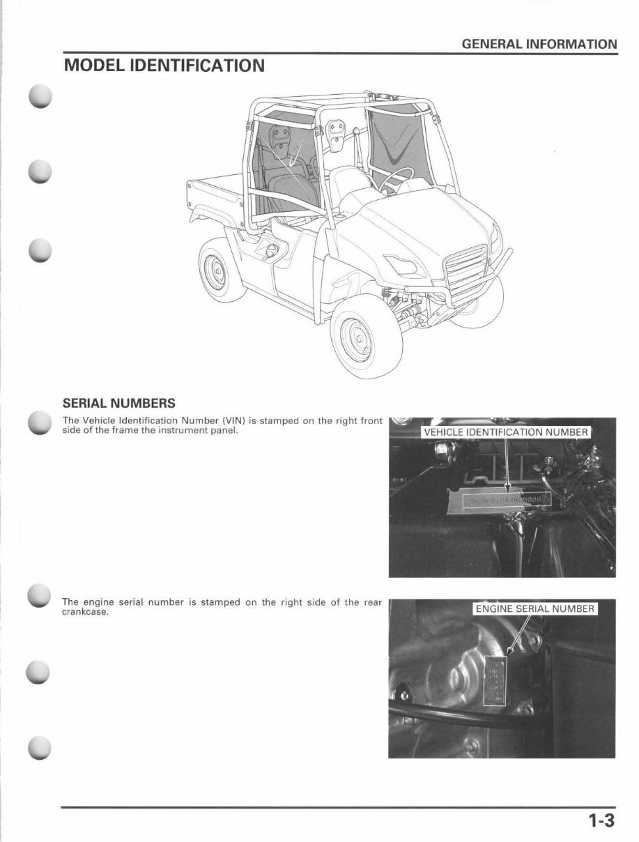
MODEL IDENTIFICATION SERIAL NUMBERS The Vehicle Identification Number (VIN) is stamped on the right front side of the frame the instrument panel. The engine serial number is stamped on the right side of the rear crankcase. GENERAL INFORMATION 1-3
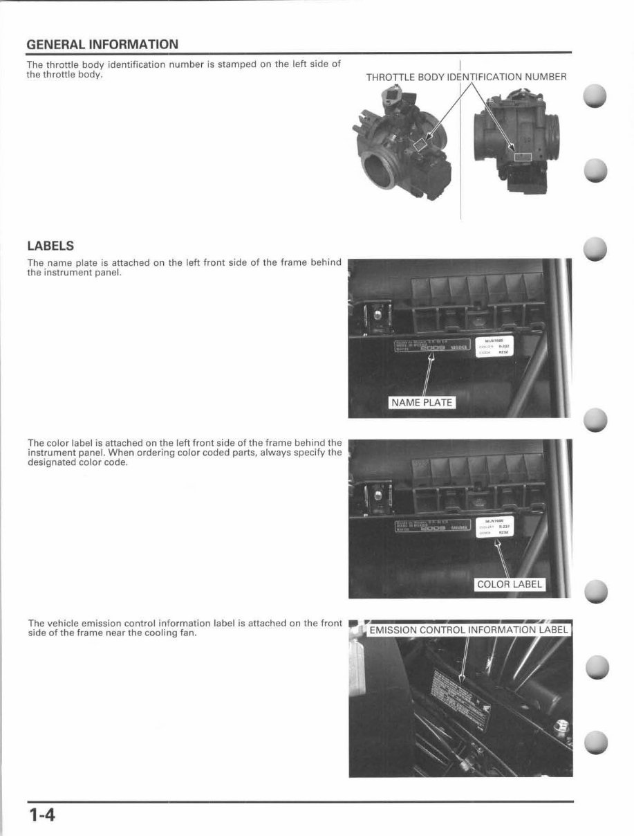
GENERAL INFORMATION The throttle body identification number is stamped on the left side of the throttle body. LABelS The name plate is attached on the left front side of the frame behind the instrument panel. The color label is attached on the left front side of the frame behind the instrument panel. When ordering color coded parts, always specify the designated color code. The vehicle emission control information label is attached on the front side of the frame near the cooling fan. 1-4 IDENTIFICIHlClN NUMBER
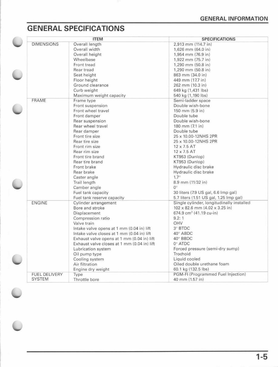
GENERAL SPECIFICATIONS Overall j Overall height Wheelbase Front tread Rea r tread Sea t height Floor height Ground clearance Curb weight Maximum Front suspension Front wheel travel Front damper Rear suspension Rea r wheel travel Rear damper Front tire size Rear tire size Front rim size Rea r rim size Front tire brand Rear lire brand Front brake Rear brake Caster angle Trail length Camber angle Fuel tank capacity Fuel tank reserve Displacement Compression ratio Valve train Intake valve opens at 1 mm (0.04 in) lift Intake valve closes at 1 mm (0.04 in) lift Exhaust valve opens at 1 mm (0.04 in) lift Exhaust valve closes at 1 mm (0.04 in) lift Lubr ication system Oil pump type Cooling system Air filtration 'i'"iicv-+~ E~ ngine dry weight FUEL DELIVERY Type GENERAL INFORMATION -+"- 0" mm (114.7 in) 1,626 mm (64.0 in) 1,954 mm (76 .9 in) 1,922 mm (75.7 in) , ,290 mm (50.8 in) 1,290 mm (50.8 in) 863 mm (34.0 in) 449 mm (17.7 in) 262 mm (10.3 in) 649 kg (1,431 Ibs) 540 space Double wish-bone 150 mm (5.9 in) Double tube Double wish-bone 180 mm (7.1 in) Double tube 25 x 10.00-12NHS 2PR 25 x 10.00-12NHS 2PR 12x7.5AT 12x7.5AT KT953 (Dunlop) KT953 (Dunlop) Hydraulic disc brake Hydraulic disc brake 1.7 0 8.9 mm (11132 in) 0' 30 liters (7.9 US gal, 6.61mp gal) PGM-FI (Programmed Fuel Injection) SYSTEM Throttle bore _____ -"--=4 .. 0"m=m " I"' ,, .5 e.- 7 in"I __________ ---.J 1-5
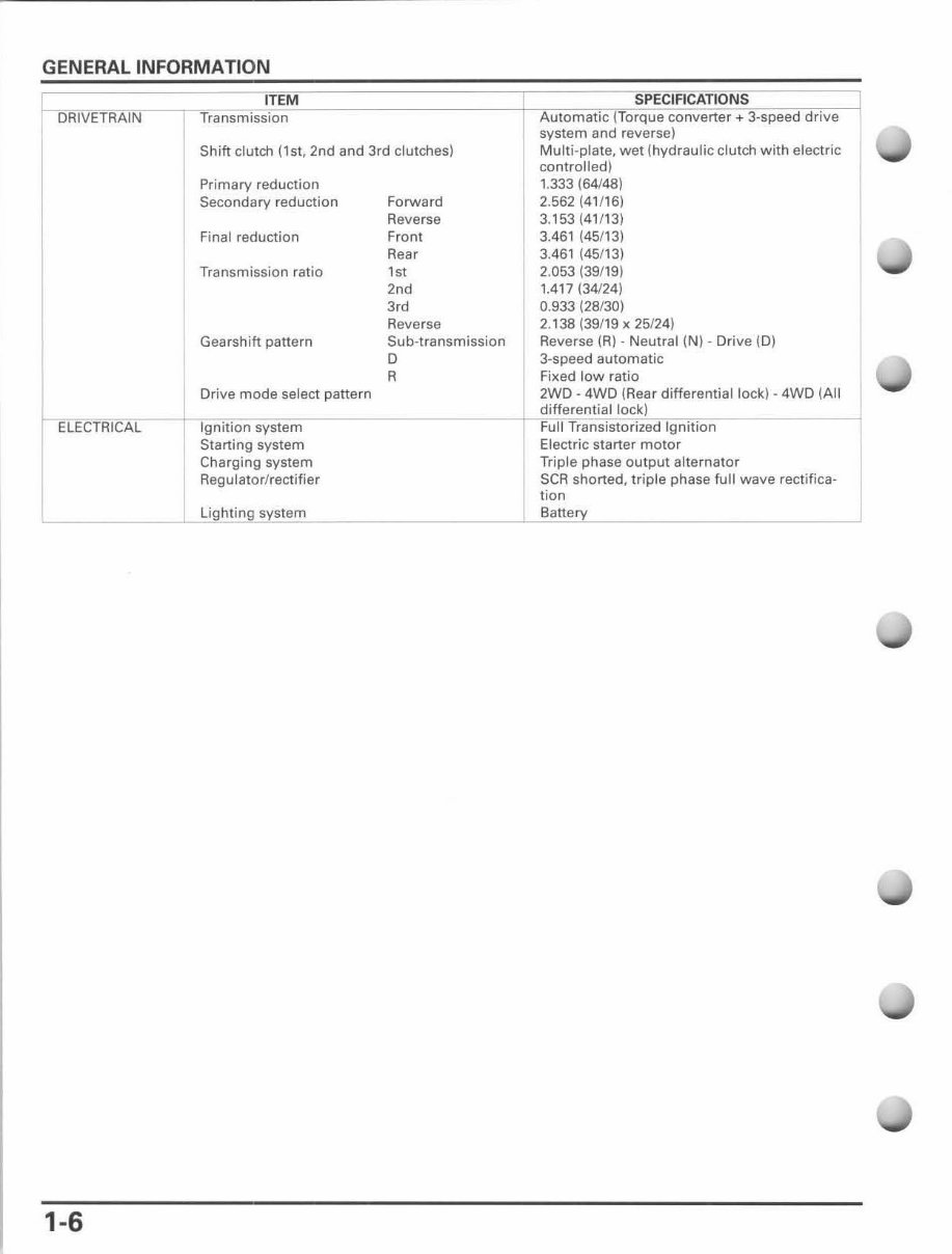
GENERAL INFORMATION ELECTRICAL 1-6 Shift clutch (lS1, 2nd and 3rd clutches) Primary reduction Secondary reduction Final reduction Forward Reverse Front Rear Transmission ratio 1st Gearshift pattern Drive mode select pattern Ignition system Starting system Charging system Reg ulator/recti' ie r Lightin g system "d 3,d Reverse Sub-transmission o R system and ,e',e,,,: Multi-plate, wet (hydraulic clutch with electric controlled) 1.333 (64148) 2.562 (41f16) 3.153 (41/13) 3.461 (45/13) 3.461 (45/13) 2,053 (39/19) 1.417 (34124) 0.933 (28/30) 2. 138 (39/19 x 25124) Reverse (A) - Neutral (N) - Drive (0) 3-speed automatic Fixed low ratio 2WD - 4WD (Rear differential lock) - 4WD (All differential lock) Full Transistorized Ignition Electric starter motor Triple phase output alternator SeR shorted, triple phase full wave rectifica- tion Battery
Get your hands on the complete workshop service repair manual for the Honda MUV700 Big Red 700 Utility Vehicle from 2009 to 2015. This comprehensive manual is a valuable resource for professional mechanics and DIY enthusiasts alike.
The manual covers every service and repair procedure with easy-to-follow step-by-step instructions and detailed pictures, enabling you to save money by performing your own repairs. Once downloaded, the manual is yours to keep forever, allowing you to print out specific pages, chapters, or the entire manual. It's also compatible with tablets for easy access.
All models, engines, trim, and transmission types are covered in this high-quality service repair workshop manual, ensuring that every repair and service procedure is included from A to Z.
Compatible with all PC and MAC computers, tablets, and mobile phones, this downloadable manual requires only Adobe Reader, which can be obtained for free. Upon payment via Visa, MasterCard, or PayPal, the manual will be instantly emailed to the address provided during checkout.
Rest assured, customer satisfaction is guaranteed with this comprehensive workshop service repair manual.
Recently Viewed
5,521,897Happy Clients
2,594,462eManuals
1,120,453Trusted Sellers
15Years in Business
Price:
Actual Price:
2009-2015 Honda Big Red MUV700 Service & Repair Manual