VMR2001_032_00_02A.FM I SECTION SUBSECTION PAGE SAFETY NOTICE ................................................................................................................................... III WHAT’S NEW ....................................................................................................................................... IV INTRODUCTION .................................................................................................................................. VI 01 SERVICE TOOLS AND SERVICE PRODUCTS 01 – Table of contents...................................................................... 01-01-1 02 – Service tools ............................................................................. 01-02-1 03 – Service products....................................................................... 01-03-1 02 MAINTENANCE 01 – Table of contents...................................................................... 02-01-1 02 – Maintenance chart.................................................................... 02-02-1 03 – Maintenance/lubrication ........................................................... 02-03-1 04 – Storage/pre-season preparation ............................................... 02-04-1 03 ENGINE 01 – Table of contents...................................................................... 03-01-1 02 – Removal and installation........................................................... 03-02-1 03 – Cooling system......................................................................... 03-03-1 04 – Rewind starter .......................................................................... 03-04-1 05 – Magneto system ...................................................................... 03-05-1 06 – Cylinder and head ..................................................................... 03-06-1 07 – Crankshaft/balancer shaft ......................................................... 03-07-1 08 – Lubrication system ................................................................... 03-08-1 09 – Clutch ....................................................................................... 03-09-1 10 – Transmission ............................................................................ 03-10-1 04 FUEL SYSTEM 01 – Table of contents...................................................................... 04-01-1 02 – Fuel circuit ................................................................................ 04-02-1 03 – Carburetor and fuel pump ........................................................ 04-03-1 04 – Air intake silencer ..................................................................... 04-04-1 05 ELECTRICAL 01 – Table of contents...................................................................... 05-01-1 02 – Overview .................................................................................. 05-02-1 03 – Charging system ...................................................................... 05-03-1 04 – Starting system ........................................................................ 05-04-1 05 – Ignition system......................................................................... 05-05-1 06 – Electric shift system................................................................. 05-06-1 07 – Instruments and accessories ................................................... 05-07-1 06 DRIVE TRAIN 01 – Table of contents...................................................................... 06-01-1 02 – Front drive ................................................................................ 06-02-1 03 – Rear axle................................................................................... 06-03-1 07 STEERING/CONTROL SYSTEMS 01 – Table of contents...................................................................... 07-01-1 02 – Steering/control systems ......................................................... 07-02-1 08 SUSPENSION 01 – Table of contents...................................................................... 08-01-1 02 – Front suspension ...................................................................... 08-02-1 03 – Rear suspension ....................................................................... 08-03-1 TABLE OF CONTENTS
II VMR2001_032_00_02A.FM 09 BRAKES 01 – Table of contents ..................................................................... 09-01-1 02 – Hydraulic brakes....................................................................... 09-02-1 10 BODY/FRAME 01 – Table of contents ..................................................................... 10-01-1 02 – Body ......................................................................................... 10-02-1 03 – Frame ....................................................................................... 10-03-1 11 TECHNICAL DATA 01 – SI metric information guide...................................................... 11-01-1 02 – Engine and vehicle ................................................................... 11-02-1 12 WIRING DIAGRAMS 01 – Wiring diagrams ....................................................................... 12-01-1 SECTION SUBSECTION PAGE TABLE OF CONTENTS
VMR2001_032_00_02A.FM III SAFETY NOTICE 0 This manual has been prepared as a guide to correctly service and repair 2001 ATVs. This edition was primarily published to be used by ATV mechanical technicians who are already familiar with all service procedures relating to Bombardier made vehicles. Mechanical technicians should attend continuous training courses given by Bombardier Training Department. Please note that the instructions will apply only if proper hand tools and special service tools are used. This shop manual uses technical terms which may be slightly different from the ones used in parts catalog. It is understood that this manual may be translated into another language. In the event of any discrepancy, the english version shall prevail. The content depicts parts and/or procedures applicable to the particular product at time of writing. Service and Warranty Bulletins may be published to update the content of this manual. Make sure to read and understand these. It does not include dealer modifications, whether authorized or not by Bombardier, after manufacturing the product. In addition, the sole purpose of the illustrations throughout the manual, is to assist identification of the general configuration of the parts. They are not to be interpreted as technical drawings or exact replicas of the parts. The use of Bombardier parts is most strongly recommended when considering replacement of any com- ponent. Dealer and/or distributor assistance should be sought in case of doubt. The engines and the corresponding components identified in this document should not be utilized on product(s) other than those mentioned in this document. Torque wrench tightening specifications must be strictly adhered to. Locking devices (ex.: locking tab, elastic stop nut, self-locking fasteners, etc.) must be installed or replaced with new ones, where specified. If the efficiency of a locking device is impaired, it must be renewed. This manual emphasizes particular information denoted by the wording and symbols: CAUTION: Denotes an instruction which, if not followed, could severely damage vehicle compo- nents. NOTE: Indicates supplementary information needed to fully complete an instruction. Although the mere reading of such information does not eliminate the hazard, your understanding of the information will promote its correct use. Always use common shop safety practice. This information relates to the preparation and use of Bombardier ATV and has been utilized safely and effectively by Bombardier Inc. However, Bombardier Inc. disclaims liability for all damages and/or injuries resulting from the improper use of the contents. We strongly recommend that any services be carried out and/or verified by a highly skilled professional mechanic. It is understood that certain modifications may render use of the vehicle illegal under existing federal, provincial and state regulations. WARNING Identifies an instruction which, if not followed, could cause serious personal injury including possibility of death. SAFETY NOTICE
IV VMR2001_032_00_02A.FM WHAT’S NEW 0 SERVICE TOOLS AND SERVICE PRODUCTS • New oil pressure gauge. MAINTENANCE/LUBRICATION • New air filter on some models. REMOVAL AND INSTALLATION • Removal and installation procedure for FOOTSHIFT model. MAGNETO SYSTEM • New section included in the shop manual. CYLINDER AND HEAD • New section included in the shop manual. CRANKSHAFT/BALANCER SHAFT • New section included in the shop manual. LUBRICATION SYSTEM • New section included in the shop manual. CLUTCH • New section included in the shop manual. TRANSMISSION • New section included in the shop manual. CARBURETOR AND FUEL PUMP • New pilot screw adjustment. AIR INTAKE SILENCER • New air intake silencer on some models. ELECTRIC SHIFT SYSTEM • Change in diagnostic mode for the new AUTO model. INSTRUMENTS AND ACCESSORIES • Complete new winch removal and installation procedure. WHAT’S NEW
VMR2001_032_00_02A.FM V FRONT DRIVE • Complete new inner differential removal and installation procedure. REAR AXLE • Complete new inner differential removal and installation procedure. FRONT SUSPENSION • Ball joints removal and installation procedure. BODY • New procedure for XL model. FRAME • New procedure for XL model. TECHNICAL DATA • New technical data for all models. WIRING DIAGRAMS • New wiring diagrams for all models. WHAT’S NEW
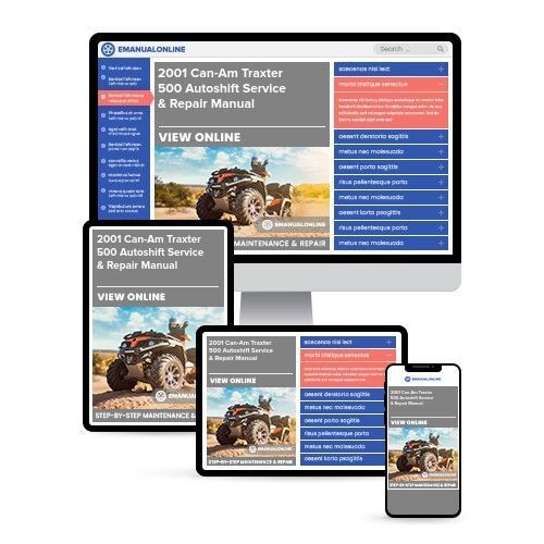
Upon purchasing this manual, you will receive a .PDF file containing an email contact. After contacting us, you will receive a reply with a link to access the manual for your Can-Am Traxter 500 Autoshift 2001.
This comprehensive manual covers every aspect of your machine, providing detailed guidance for tasks ranging from simple maintenance, such as an oil change, to more complex procedures like a transmission swap. With hundreds of pages, it includes numerous illustrations to assist you and easy-to-understand text throughout.
The manual features a search function, allowing you to easily navigate its contents and print the necessary pages. It serves as a Factory Service Repair Manual, offering a step-by-step guide to maintaining and repairing your vehicle, imparting the expertise of factory-trained technicians.
By utilizing the knowledge within this service repair manual, both professional mechanics and DIY enthusiasts can confidently make informed decisions regarding the maintenance and repair of their machine.
Our commitment extends beyond providing a high-quality service manual; we also ensure excellent customer service, guaranteeing your satisfaction.
Reviews
Q&A
Recently Viewed
5,521,897Happy Clients
2,594,462eManuals
1,120,453Trusted Sellers
15Years in Business
Price:
Actual Price:
2001 Can-Am Traxter 500 Autoshift Service & Repair Manual










 Lifetime Access




