2016 Can-Am Outlander MAX 650 XT Service & Repair Manual
What's Included?
Lifetime Access
Fast Download Speeds
Online & Offline Access
Access PDF Contents & Bookmarks
Full Search Facility
Print one or all pages of your manual
2016 Can-Am Outlander 570, 650 & 850 Standard Series This manual may cover later years than listed above. I have combined the base manual along with all the needed updates and the 2016 supplemental manual into one easy to use manual If you bought this manual from any other seller, they are reselling my work. Please leave them negative feedback & email me at bestshopmanuals@gmail.com . Our goal is to be one of the BEST sellers on eBay and the internet by providing you with the BEST customer service and the BEST manuals on the market. Thank you for choosing us.
SAFETY NOTICE SAFETY NOTICE This shop manual supplement has been prepared as a guide to correctly service and repair the 2016 Can-Am ™ Outlander ATVs as described in the model list in the INTRODUCTION. This edition was primarily published to be used by mechanics and technicians who are already familiar with all service procedures relating to BRP products. Technicians should attend training courses given by BRPTI. Please note that the instructions in this manual will apply only if proper hand tools and special ser- vice tools are used. The contents of this manual depicts parts and procedures applicable to the particular product at the time of writing. Service and warranty bulletins may be published to update the content of this manual. Dealer modifications that were carried out after manufacturing of the product, whether or not authorized by BRP, are not included. In addition, the sole purpose of the illustrations throughout the manual, is to assist identification of the general configuration of the parts. They are not to be interpreted as technical drawings or ex- act replicas of the parts. The use of BRP parts is most strongly recom- mended when considering replacement of any component. Dealer and/or distributor assistance should be sought in case of doubt. The engines and the corresponding components identified in this document should not be utilized on product(s) other than those mentioned in this document. It is understood that certain modifications may render use of the ATV illegal under existing fed- eral, provincial and state regulations. This manual emphasizes particular information de- noted by the following wording and symbols: WARNING Indicates a potential hazard that, if not avoided, could result in serious injury or death. CAUTION Indicates a hazardous situation which, if not avoided, could result in minor or moderate injury. NOTICE Indicates an instruction which, if not followed, could result in severe damage to ve- hicle components or other property. NOTE: Indicates supplementary information re- quired to fully complete an instruction. Although the mere reading of such information does not eliminate the hazard, your understanding of the information will promote its correct use. Always observe common shop safety practice. Unless otherwise noted, the engine must be stopped and the key must be removed prior to perform any services. Torque wrench tightening specifications must be strictly adhered to. Use the torque values and ser- vice products as in the exploded views or in the procedures when noted. Locking devices when removed must be replaced (e.g.: locking tabs, elastic stop nuts, self-locking fasteners, cotter pins, etc.). Hoses, cables and locking ties removed during a procedure must be reinstalled as per factory stan- dards. When ordering parts always refer to the specific model PARTS CATALOGS. We strongly recommend that any services be car- ried out and/or verified by a highly skilled profes- sional mechanic. It is understood that this manual may be trans- lated into another language. In the event of any discrepancy, the English version shall prevail. BRP disclaims liability for all damages and/or in- juries resulting from the improper use of the con- tents of this publication. vmr2016-104 I
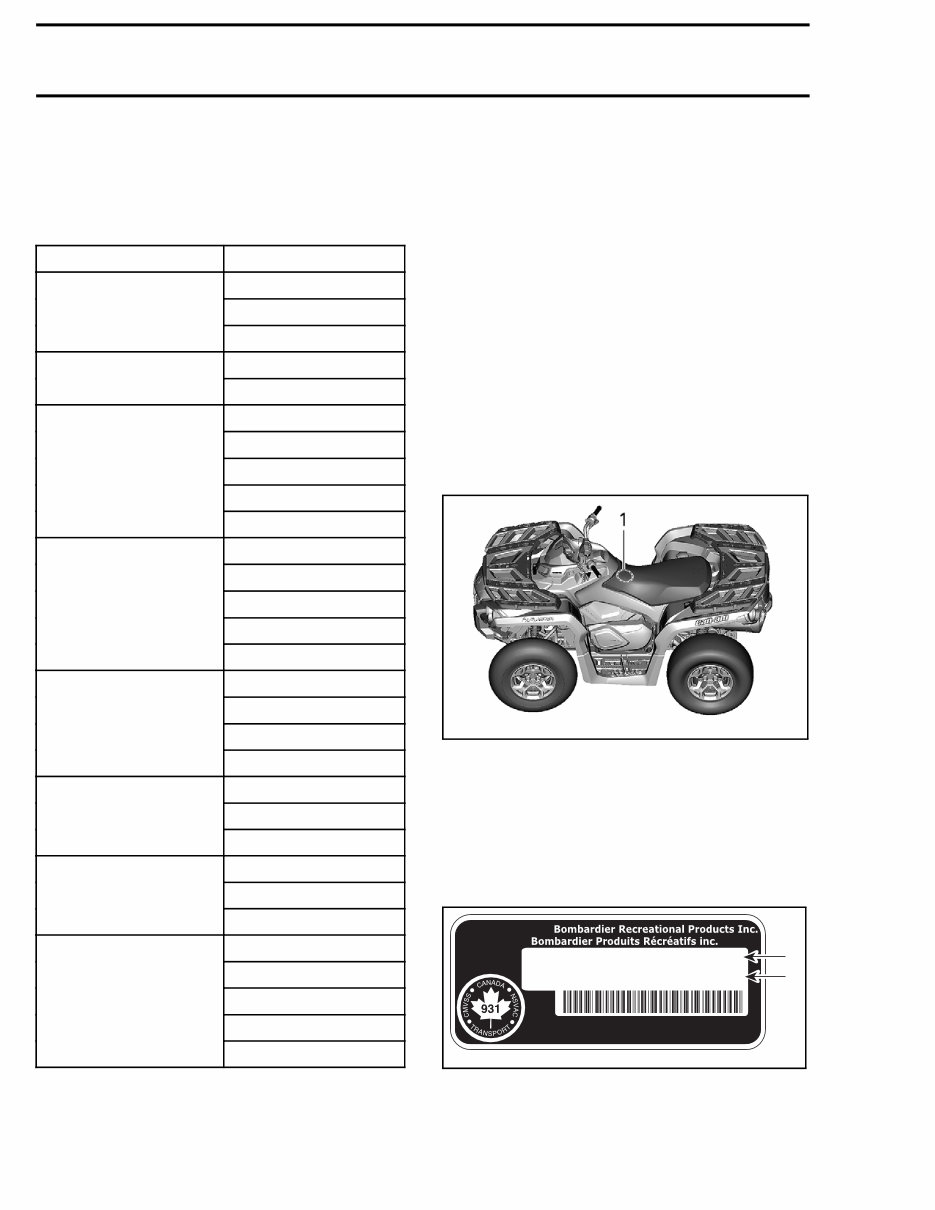
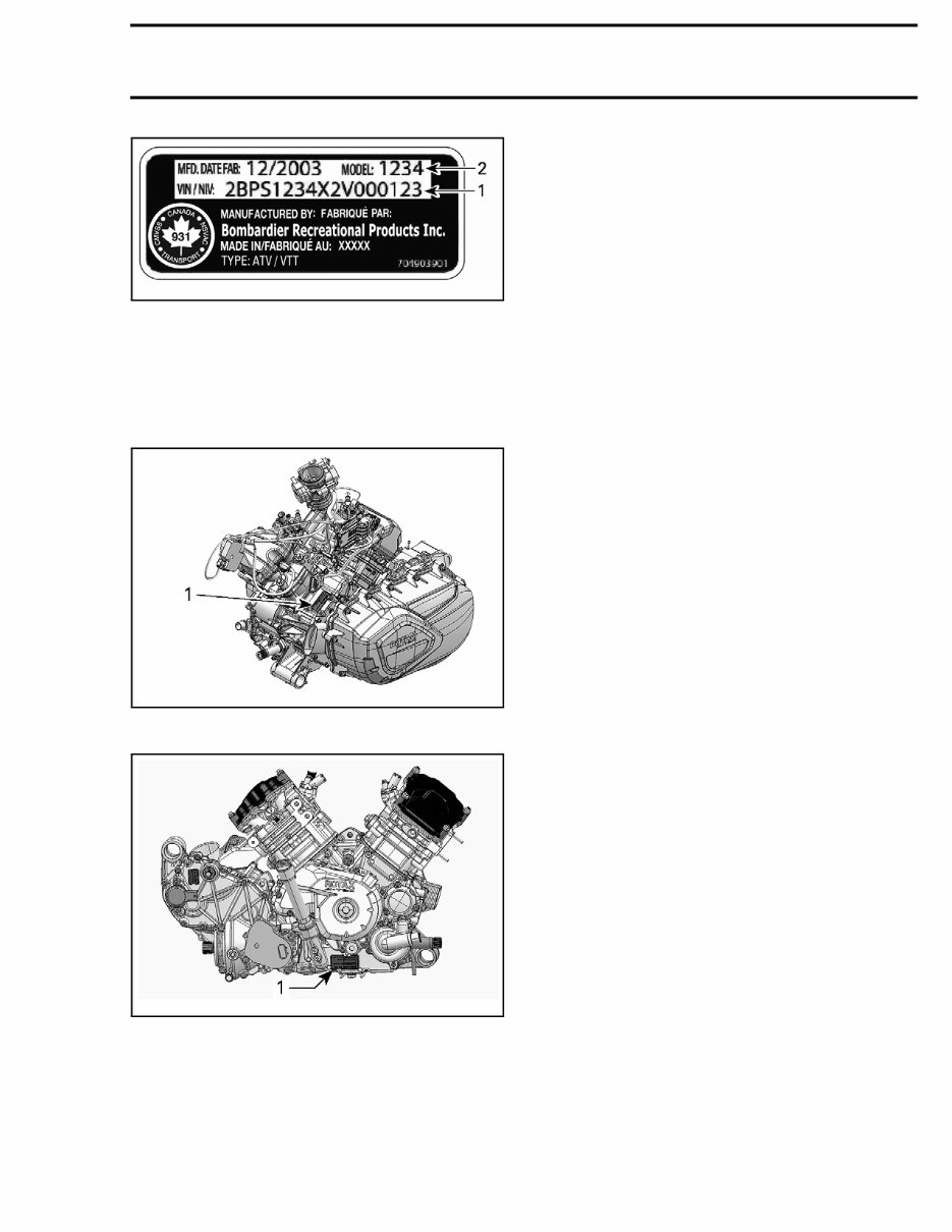
INTRODUCTION INTRODUCTION This shop manual supplement covers the follow- ing BRP made 2016 Can-Am Outlander and Out- lander MAX Series vehicles. MODEL OPTION PACKAGE DPS PRO Outlander 570 XT DPS Outlander Max 570 XT STD DPS PRO XT Outlander 650 XTP STD DPS PRO XT Outlander Max 650 XTP STD DPS XT Outlander 850 XTP DPS XT Outlander Max 850 XTP DPS XT Outlander 1000R XTP DPS LTD PRO XT Outlander Max 1000R XTP The information and component/system descrip- tions contained in this manual are correct at time of publication. BRP however, maintains a policy of continuous improvement of its products without imposing upon itself any obligation to install them on products previously manufactured. Due to late changes, there may be some differ- ences between the manufactured product and the description and/or specifications in this document. BRP reserves the right at any time to discontinue or change specifications, designs, features, mod- els or equipment without incurring obligation. VEHICLE INFORMATION VEHICLE IDENTIFICATION NUMBER (VIN) vmr2012-002-002_a TYPICAL 1. VIN (Vehicle Identification Number) location A VIN (Vehicle Identification Number) decal is lo- cated under the seat, and another on the forward RH side of the lower frame member. A vin num- ber is also stamped on the frame in this area. VIN Decal Description vmo2008-011-094_a TYPICAL — VEHICLE IDENTIFICATION NUMBER LABEL 1. VIN (Vehicle Identification Number) 2. Manufacturing date and model number II vmr2016-104
INTRODUCTION vmr2015-005-003_a TYPICAL — VEHICLE SERIAL NUMBER DECAL ON RH SIDE OF FRAME 1. VIN (Vehicle Identification Number) 2. Vehicle manufacturing date and model number ENGINE IDENTIFICATION NUMBER (EIN) vmr2016-005-001_a LH SIDE OF 570 ENGINE 1. EIN (Engine Identification Number) tmr2011-002-002_a TYPICAL - RH SIDE OF OTHER ENGINES 1. Engine Identification Number (EIN) ENGINE EMISSIONS INFORMATION MANUFACTURER'S RESPONSIBILITY Manufacturers of engines must determine the exhaust emission levels for each engine horse- power family and certify these engines with the United States of America Environmental Protection Agency (EPA). An emissions control information label, showing emission levels and engine specifications, must be placed on each vehicle at the time of manufacture. DEALER RESPONSIBILITY When servicing any vehicle that carry an emis- sions control information label, adjustments must be kept within published factory specifications. Replacement or repair of any emission related component must be executed in a manner that maintains emission levels within the prescribed certification standards. Dealers are not to modify the engine in any man- ner that would alter the horsepower or allow emis- sion levels to exceed their predetermined factory specifications. Exceptions include manufacturer's prescribed changes. OWNER RESPONSIBILITY The owner/operator is required to have engine maintenance performed to maintain emission levels within prescribed certification standards. The owner/operator is not to, and should not al- low anyone else to modify the engine in any man- ner that would alter the horsepower or allow emis- sions levels to exceed their predetermined factory specifications. EMISSION REGULATIONS The vehicle you are servicing may have been certified to applicable emission regulations in your country or state. Not as an exhaustive list; this may include standards for engine exhaust emissions, crankcase emissions, permeation emissions and evaporative emissions. Servic- ing procedures in this manual must be strictly followed in order to keep the vehicle within the factory specifications. Failure to follow servicing vmr2016-104 III
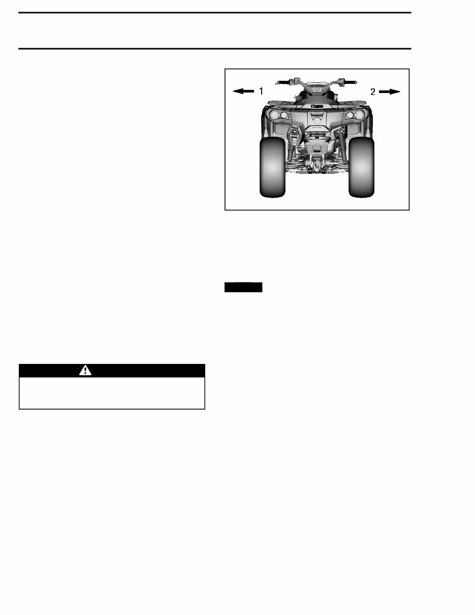
INTRODUCTION procedures in this manual may lead a vehicle to be out of compliance with applicable emission regulations. When servicing any vehicle; adjustments must be kept within published factory specifications. Re- placement or repair of any emission related com- ponent must be executed in a manner that main- tains emission levels within the applicable certifi- cation standards. Nobody is allowed to modify the engine in any manner that would alter the horse- power or allow emission levels to exceed their predetermined factory specifications. Exceptions include manufacturer’s prescribed changes. The owner/operator is required to have engine maintenance performed to maintain emission lev- els within the prescribed certification standards. The owner/operator is allowed and should not allow anyone else to modify the engine in any manner that would alter the horsepower or allow emissions levels to exceed their predetermined factory specifications. MANUAL INFORMATION MANUAL PROCEDURES Many of the procedures in this manual are inter- related. Before undertaking any task, you should read and thoroughly understand the entire section or subsection in which the procedure is contained. WARNING Unless otherwise specified, the engine should be turned OFF and cold for all main- tenance and repair procedures. A number of procedures throughout the book re- quire the use of special tools. Before starting any procedure, be sure that you have on hand all re- quired tools, or their approved equivalents. The use of RIGHT and LEFT indications in the text are always referenced to the driving position (sit- ting on the vehicle). vmr2012-002-001_a TYPICAL 1. Left 2. Right This manual uses technical terms which may be different from the ones of the parts catalogs. When ordering parts always refer to the specific model PARTS CATALOGS. NOTICE Most fasteners are metric, and most components are built with parts dimensioned using the metric system. Consult the appropri- ate PARTS CATALOG to obtain and use the cor- rect parts and fasteners. Mismatched or incor- rect fasteners could cause damage to the vehi- cle. MANUAL LAYOUT This manual is divided into many major sections as can be seen in the main table of contents at the beginning of the manual. Each section is divided into various subsections, and again, each subsection has one or more divi- sions. Illustrations and photos show the typical construc- tion of various assemblies and, in all cases, may not reproduce the full detail or exact shape of the parts used in a particular model vehicle. However, they represent parts which have the same or a similar function. IV vmr2016-104
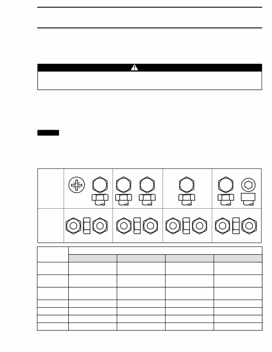
INTRODUCTION TIGHTENING TORQUE Tighten fasteners to the torque specified in the exploded view(s) and/or in the written procedure. When a torque is not specified, refer to the following table. WARNING Torque wrench tightening specifications must be strictly adhered to. Locking devices must be replaced when removed (e.g.: locking tabs, elastic stop nuts, self-lock- ing fasteners, cotter pins, etc.). In order to avoid a poor assembly, tighten screws, bolts, or nuts in accordance with the following proce- dure: 1. Manually screw in all screws, bolts and/or nuts. 2. Apply half the recommended torque value. 3. Tighten fastener to the recommended torque value. NOTICE Be sure to use the recommended tightening torque for the specified fastener used. NOTE: Whenever possible, always apply torque on the nut. NOTE: Always torque screws, bolts and/or nuts using a crisscross pattern when multiple fasteners are used to secure a part (eg. a cylinder head). Some parts must be torqued according to a specific sequence and torque pattern as detailed in the installation procedure. FASTENER GRADE/TORQUE FASTENER SIZE 5.8 Grade 8.8 Grade 10.9 Grade 12.9 Grade M4 1.5 – 2 N•m (13 – 18 lbf•in) 2.5 – 3 N•m (22 – 27 lbf•in) 3.5 N•m - 4 N•m (31 lbf•in - 35 lbf•in) 4 N•m - 5 N•m (35 lbf•in - 44 lbf•in) M5 3 N•m - 3.5 N•m (27 lbf•in - 31 lbf•in) 4.5 N•m - 5.5 N•m (40 lbf•in - 49 lbf•in) 7 N•m - 8.5 N•m (62 lbf•in - 75 lbf•in) 8 N•m - 10 N•m (71 lbf•in - 89 lbf•in) M6 6.5 N•m - 8.5 N•m (58 lbf•in - 75 lbf•in) 8 N•m - 12 N•m (71 lbf•in - 106 lbf•in) 10.5 – 15 N•m (93 – 133 lbf•in) 16 N•m (142 lbf•in) M8 15 N•m (133 lbf•in) 25 N•m (18 lbf•ft) 32 N•m (24 lbf•ft) 40 N•m (30 lbf•ft) M10 29 N•m (21 lbf•ft) 48 N•m (35 lbf•ft) 61 N•m (45 lbf•ft) 73 N•m (54 lbf•ft) M12 52 N•m (38 lbf•ft) 85 N•m (63 lbf•ft) 105 N•m (77 lbf•ft) 128 N•m (94 lbf•ft) M14 85 N•m (63 lbf•ft) 135 N•m (100 lbf•ft) 170 N•m (125 lbf•ft) 200 N•m (148 lbf•ft) vmr2016-104 VII
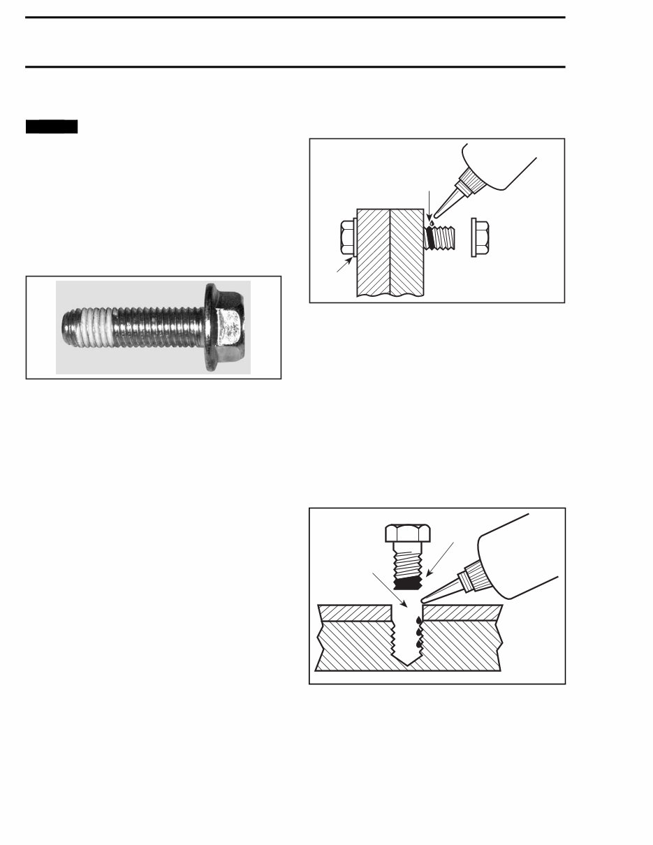
INTRODUCTION FASTENER INFORMATION NOTICE Most components in the vehicles are built with parts dimensioned in the metric system. Most fasteners are metric and must not be replaced by customary fasteners or vice-versa. Mismatched or incorrect fasteners could cause damage to the vehicle or possible personal injury. SELF-LOCKING FASTENER PROCEDURE A00A6LA TYPICAL — SELF-LOCKING FASTENER The following describes common procedures used when working with self-locking fasteners. Use a metal brush or a tap to properly clean a threaded hole, then use a solvent. Allow the sol- vent time to act, approximately 30 minutes, then wipe off. Solvent utilization is to ensure proper adhesion of the product used for locking the fas- tener. LOCTITE ® THREADLOCKER APPLICATION PROCEDURE The following describes common procedures used when working with Loctite products. NOTE: Always use proper strength Loctite prod- uct as recommended in this Shop Manual. Threadlocker Application for Uncovered Holes (Bolts and Nuts) 1. Apply here 2. Do not apply 1. Clean threads (bolt and nut) with solvent. 2. Apply LOCTITE 7649 (PRIMER) (P/N 293 800 041) on threads and allow to dry. 3. Choose proper strength Loctite threadlocker. 4. Fit bolt in the hole. 5. Apply a few drops of threadlocker at proposed tightened nut engagement area. 6. Position nut and tighten as required. Threadlocker Application for Blind Holes lmr2007-040-004_a 1. On fastener threads 2. On threads and at the bottom of hole 1. Clean threads (bolt and hole) with solvent. 2. Apply LOCTITE 7649 (PRIMER) (P/N 293 800 041) on threads (bolt and nut) and allow to dry for 30 seconds. 3. Choose proper strength Loctite threadlocker. VIII vmr2016-104
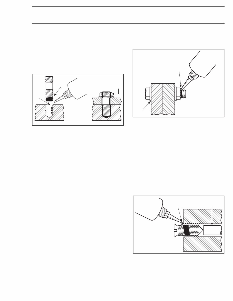
INTRODUCTION 4. Apply several drops along the threaded hole and at the bottom of the hole. 5. Apply several drops on bolt threads. 6. Tighten as required. Threadlocker Application for Stud Installation in Blind Holes lmr2007-040-005_a 1. On stud threads 2. On threads and in the hole 3. On retaining nut threads 1. Clean threads (stud and hole) with solvent. 2. Apply LOCTITE 7649 (PRIMER) (P/N 293 800 041) on threads and allow to dry. 3. Apply 2 or 3 drops of proper strength Loctite threadlocker on female threads and in hole. NOTE: To avoid a hydro lock situation, do not ap- ply too much Loctite. 4. Apply several drops of proper strength Loctite on stud threads. 5. Install stud. 6. Install cover, part, etc. 7. Apply a few drops of proper strength Loctite on uncovered stud threads. 8. Install and tighten retaining nut(s) as required. Threadlocker Application for Pre-Assembled Parts A00A3OA 1 2 1. Apply here 2. Do not apply 1. Clean bolts and nuts with solvent. 2. Assemble components. 3. Tighten nuts. 4. Apply a few drops of proper strength Loctite on bolt/nut contact surfaces. 5. Avoid touching metal with tip of flask. NOTE: For preventive maintenance on exist- ing equipment, retighten nuts and apply proper strength Loctite on bolt/nut contact surfaces. Threadlocker Application for an Adjustment Screw 1. Apply here 2. Plunger 1. Adjust screw to proper setting. 2. Apply a few drops of proper strength Loctite threadlocker on screw/body contact surfaces. 3. Avoid touching metal with tip of flask. vmr2016-104 IX
The Can-Am Outlander MAX 650 XT Service & Repair Manual is an essential resource for professional technicians and do-it-yourself mechanics alike. This complete official full factory service repair manual provides comprehensive guidance for repairing and maintaining the Can-Am Outlander MAX 650 XT.
Featuring easy-to-read text sections, high-quality diagrams, and step-by-step instructions, this manual covers all aspects of the machine, offering detailed insights for efficient repairs. Whether you're a professional mechanic or a DIY enthusiast, this manual equips you with the knowledge needed to make informed decisions about maintaining and repairing the Can-Am Outlander MAX 650 XT.
Upon purchase, you will receive instant access to the manual in either .PDF or .OVA file format, allowing you to start your repairs without any waiting or shipping delays. The manual includes critical specifications, illustrations, maintenance procedures, disassembly and assembly instructions, cleaning and reinstalling procedures, and much more.
With the ability to zoom in and out, this manual provides a user-friendly experience for all versions of Windows and Mac. It does not require any additional software and is delivered instantly upon purchase, ensuring a hassle-free experience.
In summary, the Can-Am Outlander MAX 650 XT Service & Repair Manual is a valuable resource that empowers both professional technicians and DIY enthusiasts to effectively maintain and repair the Can-Am Outlander MAX 650 XT.
Recently Viewed
5,521,897Happy Clients
2,594,462eManuals
1,120,453Trusted Sellers
15Years in Business
Price:
Actual Price:
2016 Can-Am Outlander MAX 650 XT Service & Repair Manual