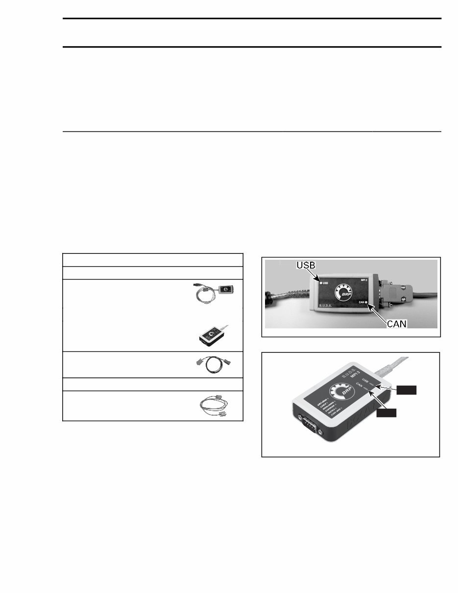
Subsection XX (COMMUNICATION TOOLS AND B.U.D.S.) COMMUNICATION TOOLS AND B.U.D.S. SERVICE TOOLS Description Part Number Page DIAGNOSTIC CABLE .................................................................... 710 000 851 ......................................... 1, 3 MPI-2 INTERFACE CARD .............................................................. 529 036 018 ............................................. 1 MPI-3 INTERFACE CARD .............................................................. 529 036 353 ............................................. 1 GENERAL Refer to PROCEDURES for instructions on the communication tools. If communication problems occur, refer to TROU- BLESHOOTING in this subsection. REQUIRED TOOLS MANDATORY TOOLS A personal computer (laptop or desktop) MPI-2 INTERFACE CARD (P/N 529 036 018) OR MPI-3 INTERFACE CARD (P/N 529 036 353) DIAGNOSTIC CABLE (P/N 710 000 851) OPTIONAL TOOL Extension cable available at electronic retail outlets. Do not exceed 7.5 m (25 ft) TROUBLESHOOTING DIAGNOSTIC TIPS IMPORTANT: Make sure all connections are made and vehicle is powered up before starting B.U.D.S. to allow proper communication between the vehicle and the BRP Utility and Diagnostic Software (B.U.D.S.). Multi-Purpose Interface Card Connection Troubleshooting MPI Status Lights The MPI card includes 2 status lights that indi- cate the connection condition: USB and CAN. Both lights must be GREEN to function properly. Otherwise, refer to the following charts. vdd2006-001-151_b MPI-2 CARD CAN USB vmr2016-128-001_a MPI-3 CARD Prerequisite for USB Communication: – PC Computer turned on. – MPI card connected to PC computer. tmr2016-212 1
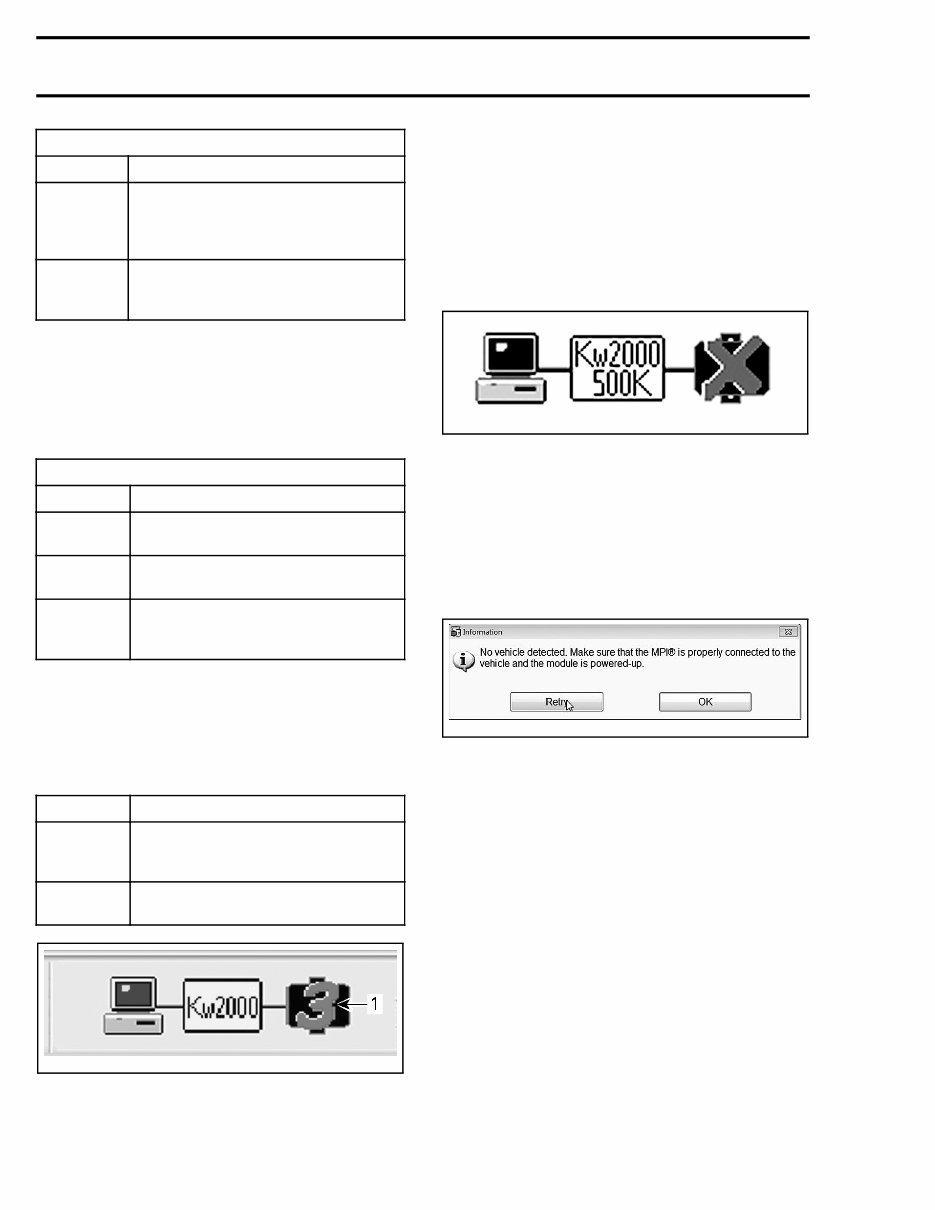
Subsection XX (COMMUNICATION TOOLS AND B.U.D.S.) USB LIGHT STATUS WHAT TO DO Light is OFF Check USB connection between MPI card and PC computer. Check USB operation on PC computer (hardware or USB drivers) Light is GREEN Connections are GOOD. Communication can take place on USB side Prerequisite for CAN Communication: – MPI card connected to diagnostic connector on vehicle. – Ignition key installed and turned to ON (electri- cal system powered up without engine started). – B.U.D.S. started and logged on. CAN LIGHT STATUS WHAT TO DO Light is OFF Check connection between MPI card and diagnostic connector on vehicle Light is RED Check CAN wires/connectors on vehicle Light is GREEN Connections are GOOD. Communication can take place on CAN side Communication Problems when Using B.U.D.S. Missing Module Ensure the appropriate number of modules is shown at the bottom of B.U.D.S. screen. MODEL NUMBER OF MODULES Models without DPS 2 (ECM and multifunction gauge) Models with DPS 3 (ECM, DPS and multifunction gauge) vmr2016-128-002_a TYPICAL 1. Number of modules If one or more “ECU” is not communicating with the MPI card, refer to DIAGNOSTIC AND FAULT CODES. No Vehicle is Detected If an “X” is shown in the status bar and the pro- tocol indication is blinking between Kw2000 500K and KW2000, it means that no "ECU" is communi- cating with the MPI card. rmr2010-020-009 Check the following: – Connections between the PC computer and the vehicle. – The multifunction gauge is powered up. If B.U.D.S. does not automatically exit the follow- ing message box, click the Retry button. This will manually establish the communication with the vehicle. rmr2015-124-005 PROCEDURES MULTI-PURPOSE INTERFACE CARD (MPI-2 OR MPI-3) The MPI (Multi-Purpose Interface) in conjunction with the diagnostic cable is used with B.U.D.S. to communicate with the ECM (engine control mod- ule) and other modules. MPI Card Power The MPI card uses the power from the PC com- puter's USB port. Diagnostic Connector Location The 6-pin diagnostic connector is located under the hood, stored in it's protective cap. 2 tmr2016-212
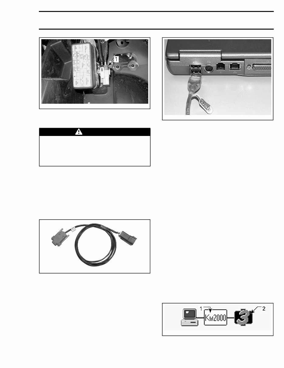
Subsection XX (COMMUNICATION TOOLS AND B.U.D.S.) tmr2013-076-001_a 1. Diagnostic connector Connecting the PC to the Vehicle WARNING If the computer you are using is connected to the 110 Vac power outlet, there is a poten- tial risk of electrocution when working in con- tact with water. Be careful not to touch water while working with the VCK. 1. Locate the 6-pin diagnostic connector, refer to DIAGNOSTIC CONNECTOR LOCATION in this subsection. 2. Disconnect the 6-pin diagnostic connector from it's holder (protective cap). 3. Connect one end of the DIAGNOSTIC CABLE (P/N 710 000 851) to the vehicle connector. 710000851 DIAGNOSTIC CABLE CONNECTED TO VEHICLE 4. Connect the other end of diagnostic cable to the MPI card. 5. Connect the MPI card to the USB port of a PC (personal computer). mmr2006-079-200 MPI CARD CABLE CONNECTED TO USB PORT 6. Use B.U.D.S. as described further in B.U.D.S. SOFTWARE topic B.U.D.S. SOFTWARE B.U.D.S. is designed for: – Programming ignition key(s) to the vehicle – Monitoring some electrical and electronic com- ponents – Activating certain components for diagnostic purposes – Updating electronic module software – And, to carry out setting changes. Always use the latest applicable B.U.D.S. version available on Knowledge Center. Reading the Electronic Control Units Using B.U.D.S. Software IMPORTANT: Ensure all connections have been made before starting B.U.D.S. to allow proper op- eration. Refer to CONNECTING THE PC TO THE VEHICLE in this subsection. 1. Turn ignition switch to ON position (ACC will not work). Do not start the engine. 2. Start B.U.D.S. and logon. 3. Ensure the status bar shows the appropriate protocol and the appropriate number of mod- ules to its right according to the vehicle model. tmr2015-028-003_a TYPICAL - SUCCESSFUL CONNECTION 1. Connection protocol 2. Number of modules read tmr2016-212 3
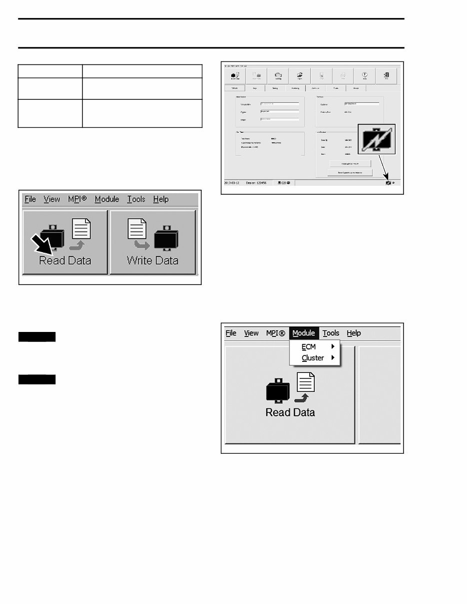
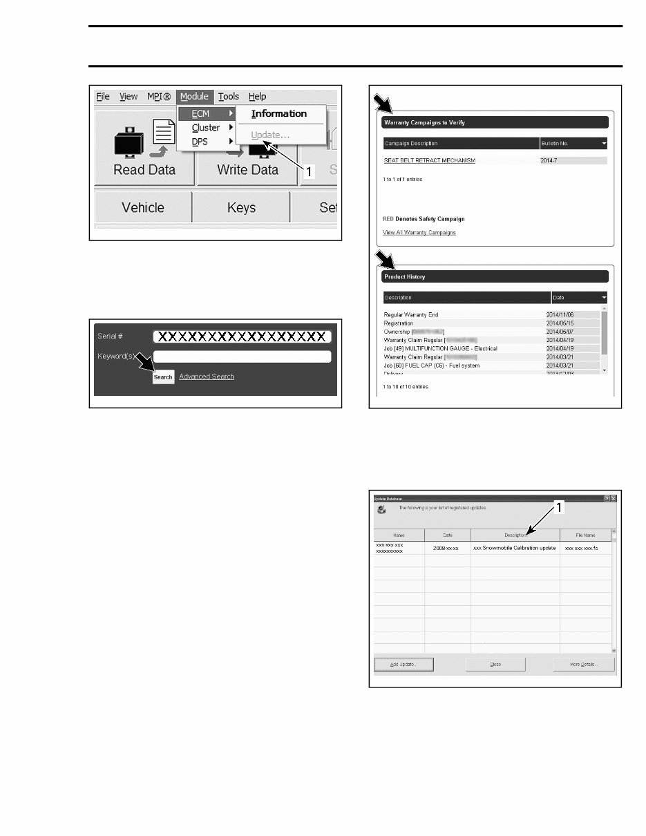
Subsection XX (COMMUNICATION TOOLS AND B.U.D.S.) MODEL NUMBER OF MODULES Models without DPS 2 (ECM and multifunction gauge) Models with DPS 3 (ECM, DPS and multifunction gauge) If the number is less than indicated in NUMBER OF MODULES table, refer to TROUBLESHOOT- ING in this subsection. 4. Read the ECUs by clicking the Read Data but- ton. vmr2006-012-100_aen B.U.D.S. is now ready to use. Updating Electronic Module (ECU) Software NOTICE Vehicle voltage should be stable dur- ing the update process (no disconnection on the MPI, battery or key to OFF) to make sure up- dates are processed properly NOTICE Failure to strictly follow a procedure to update a module may permanently damage the module. Whenever B.U.D.S. is first connected to a vehicle, check for an update icon in the status bar at the bottom of the Vehicle page. smr2010-030-002_a TYPICAL If the update icon is visible, B.U.D.S. indicates that a file is available to update at least one of the elec- tronic modules: NOTE: If an update file is available on KNOWL- EDGE CENTER but the B.U.D.S. software being used is not up to date, the update icon will not ap- pear. Refer to the SERVICE BULLETINS to see if there is an update available. Use the Module submenu and check all modules one at a time to see which module(s) can be up- dated. lmr2010-019-001 TYPICA L - MODULE SUBMENU LIST 1. If the Update option is greyed out, no update file is available for this module. 2. If the Update option is black, an update file is available for this module. 4 tmr2016-212
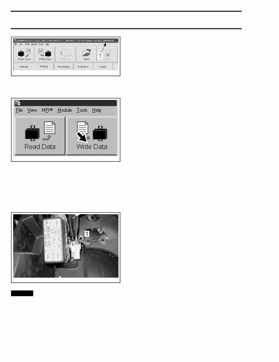
Subsection XX (COMMUNICATION TOOLS AND B.U.D.S.) vbl2012-007-010_a 1. Greyed out: No update to perform Black: Update file available Before applying an update, log onto KNOWL- EDGE CENTER and search the vehicle's VIN to find the unit's history. tmr2015-028-001_a Complete all WARRANTY CAMPAIGNS TO VER- IFY. NOTE: PRODUCT HISTORY will show all repairs performed and claimed under warranty. tmr2015-028-002_a NOTE: When selecting the update menu in B.U.D.S., a dialog box will appear and the update file description may give some clue to finding the vehicle-related information on KNOWLEDGE CENTER . mbg2008-022-100_a TYPICAL 1. File description Saving Changes to an ECU If the word Modified appears at the end of the ve- hicle file name at the top of the B.U.D.S. page, then a change has been made that requires it to be saved to the proper electronic module. tmr2016-212 5
Subsection XX (COMMUNICATION TOOLS AND B.U.D.S.) rmr2010-020-008_a TYPICAL 1. Indicate setting or data modified; Write Data to save Click the Write Data button. vmr2006-012-100_ben NOTE: A message box will confirm a successful operation. In such a case, turn ignition switch OFF, then wait for the message to disappear before disconnect- ing the MPI. Disconnect MPI card and store the vehicle diag- nostic connector in its protective cap. tmr2013-076-001_a 1. Diagno stic connector in its storage cap NOTICE Failure to secure the diagnostic con- nector in its protective cap may result in corro- sion or other damage to the terminals. 6 tmr2016-212
SAFETY NOTICE SAFETY NOTICE This manual has been prepared as a guide to correctly service and repair the 2016 Can-Am ™ Maverick ™ . This edition was primarily published to be used by mechanical technicians who are already familiar with all service procedures relating to BRP prod- ucts. Mechanical technicians should attend train- ing courses given by BRPTI. Please note that the instructions in this manual will apply only if proper hand tools and special ser- vice tools are used. The contents of this manual depicts parts and/or procedures applicable to a particular product at the time of writing. Service and warranty bulletins may be published to update the content of this manual. Dealer modifications that were carried out after manufacturing of the product, whether or not authorized by BRP, are not included. In addition, the sole purpose of the illustrations throughout the manual, is to assist identification of the general configuration of the parts. They are not to be interpreted as technical drawings or ex- act replicas of the parts. The use of BRP parts is most strongly recom- mended when considering replacement of any component. Dealer and/or distributor assistance should be sought in case of doubt. The engines and the corresponding components identified in this document should not be utilized on product(s) other than those mentioned in this document. It is understood that certain modifications may render use of the vehicle illegal under existing federal, provincial and state regulations. This manual emphasizes particular information which, is denoted by the following wording and symbols: WARNING Indicates a potential hazard that, if not avoided, could result in serious injury or death. CAUTION Indicates a hazardous situation which, if not avoided, could result in minor or moderate injury. NOTICE Indicates an instruction which, if not followed, could result in severe damage to ve- hicle components or other property. NOTE: Indicates supplementary information re- quired to fully complete an instruction. Although the mere reading of such information does not eliminate the hazard, your understand- ing of the information provided will promote its correct use. Always observe common shop safety practice. Unless otherwise noted, the engine must be stopped and the tether cord must be removed prior to perform any services. Torque wrench tightening specifications must be strictly adhered to. Use the torque values and ser- vice products as in the exploded views or in the procedures when noted. Locking devices when removed must be replaced (e.g.: locking tabs, elastic stop nuts, self-locking fasteners, cotter pins, etc.). Hoses, cables and locking ties removed during a procedure must be reinstalled as per factory stan- dards. When ordering parts always refer to the specific model PARTS CATALOGS. We strongly recommend that any services be car- ried out and/or verified by a highly skilled profes- sional mechanic. It is understood that this manual may be trans- lated into another language. In the event of any discrepancy, the English version shall prevail. BRP disclaims liability for all damages and/or in- juries resulting from the improper use of the con- tents of this publication. tmr2016-200 I
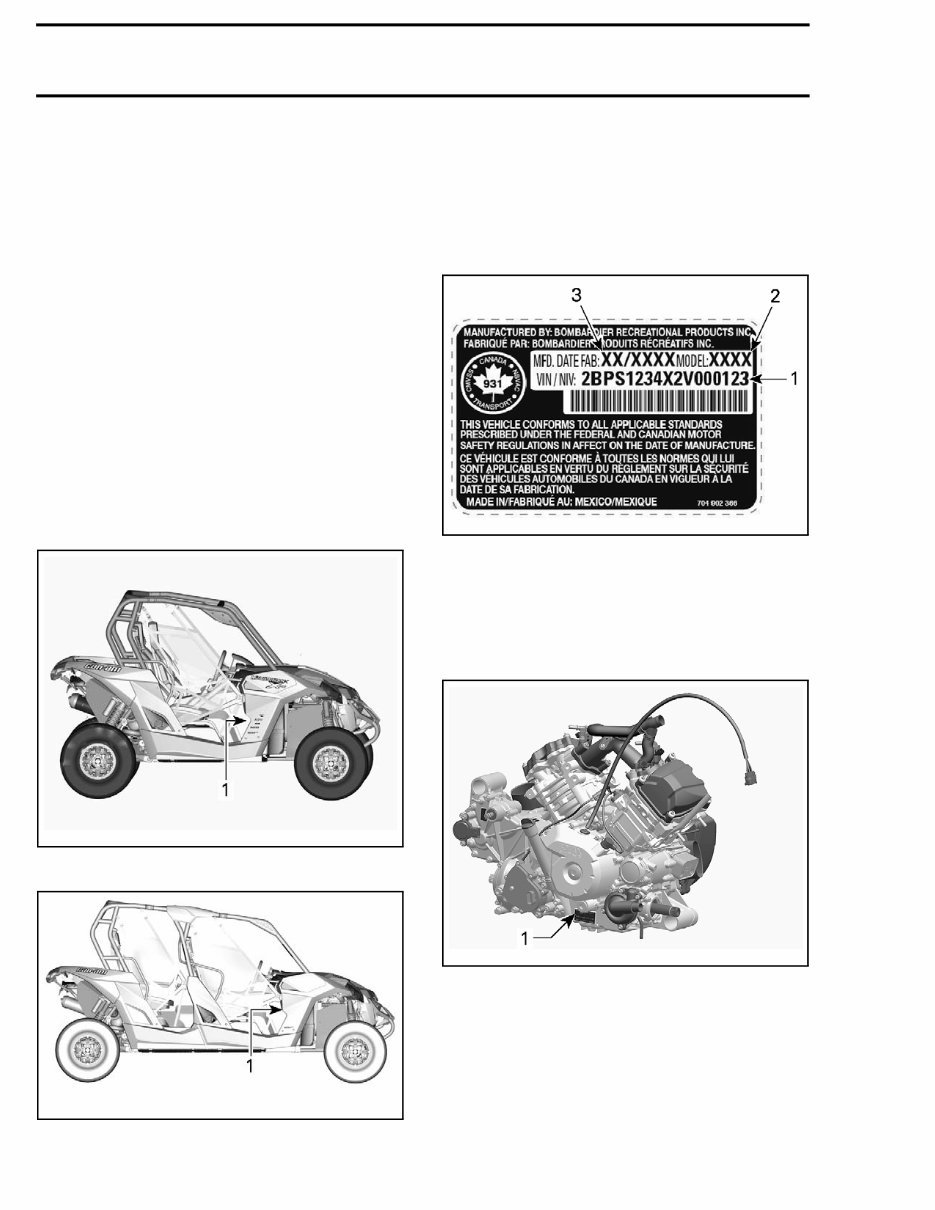
INTRODUCTION INTRODUCTION The information and component/system descrip- tions contained in this manual are correct at time of writing. BRP however, maintains a policy of continuous improvement of its products without imposing upon itself any obligation to install them on products previously manufactured. Due to late changes, there may be some differ- ences between the manufactured product and the description and/or specifications in this document. BRP reserves the right at any time to discontinue or change specifications, designs, features, mod- els or equipment without incurring obligation. VEHICLE INFORMATION VEHICLE IDENTIFICATION NUMBER (VIN) tmo2013-003-008_a 2-UP MODEL 1. VIN (Vehicle Identification Number) location tmr2014-104-001_b MAX MODEL 1. VIN (Vehicle Identification Number) location The VIN (Vehicle Identification Number) decal is lo- cated under the glove box on the passenger side. VIN Decal Description tmr2011-002-005_a TYPICAL — VEHICLE IDENTIFICATION NUMBER LABEL 1. VIN (Vehicle Identification Number) 2. Model number 3. Manufacturing date ENGINE IDENTIFICATION NUMBER (EIN) tmo2011-001-401_a TYPICAL — ENGINE SERIAL NUMBER LABEL 1. EIN (Engine Identification Number) LIFTING AND SUPPORTING THE VEHICLE NOTE: Please remove this page and keep with the Operator's guide in the vehicle for future reference. II tmr2016-200
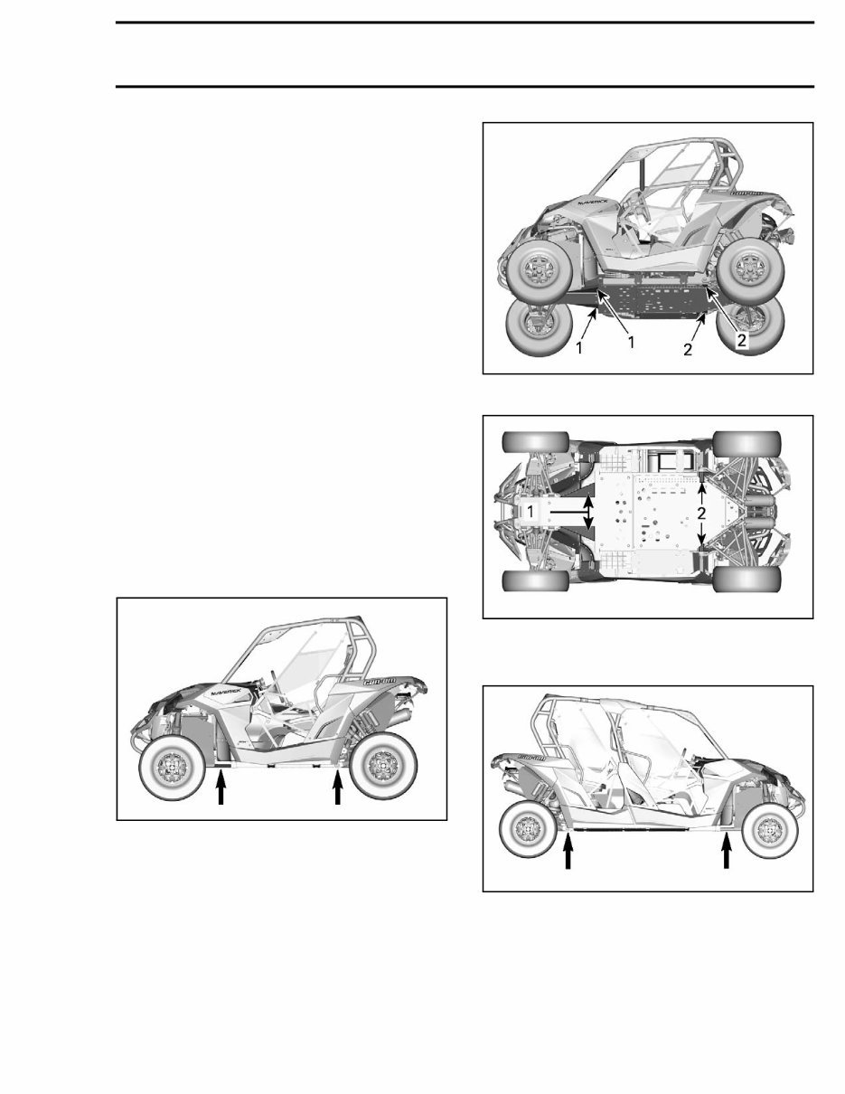
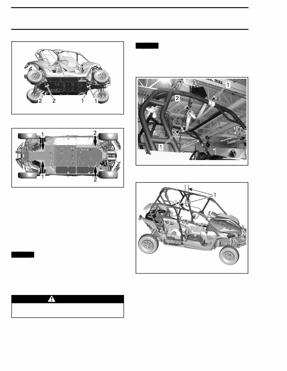
INTRODUCTION To lift your vehicle, you must be on a flat and non slippery ground. Make sure the wheel jack base gives a good support. Remove all debris that could cause the wheel jack to tip over. Front of Vehicle Place vehicle on a flat non slippery ground. Ensure vehicle shift lever is set to PARK. Place wheel jack on one of the identified points shown in the following images. Lower hydraulic lift and ensure vehicle is sup- ported safely onto both jack stands. Rear of Vehicle Place vehicle on a flat non slippery ground. Activate 4WD mode. Ensure vehicle shift lever is set to PARK. Place wheel jack on one of the identified points shown in the following images. Lower hydraulic lift and ensure vehicle is sup- ported safely onto both jack stands. Identification of lifting points 2-Up Models tsi2013-044-020_a tsi2013-044-019_a 1. Front lifting points 2. Rear lifting points tsi2013-044-018_a 1. Front lifting points 2. Rear lifting points MAX Models tmr2014-104-001_a tmr2016-200 III
INTRODUCTION tmr2014-104-003_a 1. Front lifting points 2. Rear lifting points tmr2014-104-002-a 1. Front lifting points 2. Rear lifting points LIFTING THE VEHICLE WITH A LIFTING TABLE Roll vehicle above lifting table. Install two 4 x 4 horizontally across vehicle as close as possible to lifting points. Refer to IDEN- TIFICATION OF LIFTING POINTS in this subsec- tion. NOTICE Ensure 4 x 4 are as close to lifting points as possible. Lift vehicle using table. NOTE: If repositioning of vehicle is needed, lift ei- ther front or rear of vehicle using the lower portion of applicable bumper. WARNING – Do not allow anyone in the vehicle while it is being lifted. HOISTING THE VEHICLE The vehicle may be lifted off the ground by the cage using a hoist and a lifting strap. NOTICE The lifting strap must be wrapped around the horizontal side tubes at the top of the cage, NOT fore and aft. Lifting vehicle by the fore and aft tubes of the cage can cause damage. tmr2011-002-004_a 2-UP MODELS 1. Lifting strap around horizontal side tubes (top) 2. Hoist hook tmr2014-104-005_a MAX MODELS 1. Lifting strap at the center of the middle section, around horizontal side tubes (top) IV tmr2016-200
A shop manual for the 2016 Can Am Maverick and Maverick Turbo is an essential resource for anyone involved in car repair. Whether you are a professional mechanic or a DIY enthusiast, these manuals provide detailed technical information to assist in the maintenance, repair, and troubleshooting of the vehicles.
These manuals are available in .PDF format, providing comprehensive guidance on various aspects of the vehicle, including engine, electrical system, chassis, and more. The detailed illustrations and step-by-step instructions make it easier to understand and perform complex repairs and maintenance tasks.
With the help of these manuals, users can gain insights into the vehicle's systems, components, and specifications, enabling them to carry out repairs and maintenance with confidence. The clear and concise nature of the content makes it a valuable resource for individuals looking to enhance their understanding of vehicle mechanics.