

2002 Bombardier DS90 2-Stroke ATV Service & Repair Manual
What's Included?
Fast Download Speeds
Online & Offline Access
Access PDF Contents & Bookmarks
Full Search Facility
Print one or all pages of your manual

2002
Shop Manual
DS50
DS90
DS90 (4-STROKE)

SECTION SUBSECTION PAGE
TABLE OF CONTENTS .......................................................................................................... I
SAFETY NOTICE .................................................................................................................... III
INTRODUCTION ................................................................................................................... V
01 SERVICE TOOLS AND
SERVICE PRODUCTS
01 – Table of contents .................................................................... 01-01-1
02 – Service tools ........................................................................... 01-02-1
03 – Service products ..................................................................... 01-03-1
02 MAINTENANCE 01 – Table of contents .................................................................... 02-01-1
02 – Maintenance chart .................................................................. 02-02-1
03 ENGINE 01 – Table of contents .................................................................... 03-01-1
02 – Removal and installation ....................................................... 03-02-1
03 – Generator, starter motor ........................................................ 03-03-1
04 – Cylinder and head .................................................................. 03-04-1
05 – Crankcase/crankshaft ............................................................. 03-05-1
06 – Lubrication system ................................................................. 03-06-1
07 – Transmission/kick start .......................................................... 03-07-1
08 – Clutch....................................................................................... 03-08-1
09 – Exhaust system....................................................................... 03-09-1
04 FUEL SYSTEM 01 – Table of contents .................................................................... 04-01-1
02 – Fuel circuit ............................................................................... 04-02-1
03 – Carburetor and air cleaner ..................................................... 04-03-1
05 ELECTRICAL 01 – Table of contents .................................................................... 05-01-1
02 – Charging system..................................................................... 05-02-1
03 – Starting system....................................................................... 05-03-1
04 – Ignition system ....................................................................... 05-04-1
06 DRIVE TRAIN 01 – Table of contents .................................................................... 06-01-1
02 – Chain drive system................................................................. 06-02-1
07 STEERING/CONTROL
SYSTEMS
01 – Table of contents .................................................................... 07-01-1
02 – Steering/control systems ....................................................... 07-02-1
08 SUSPENSION 01 – Table of contents .................................................................... 08-01-1
02 – Front suspension .................................................................... 08-02-1
03 – Rear suspension ..................................................................... 08-03-1
09 BRAKES 01 – Table of contents .................................................................... 09-01-1
02 – Brakes ...................................................................................... 09-02-1
10 TECHNICAL DATA 01 – SI metric information guide................................................... 10-01-1
02 – Engine and vehicle ................................................................. 10-02-1
11 WIRING DIAGRAMS 01 – Wiring diagrams ..................................................................... 11-01-1
TABLE OF CONTENTS

VMR2002_105_00_02AB.FM III
SAFETY NOTICE 0
This manual has been prepared as a guide to correctly service and repair 2002 ATVs.
This edition was primarily published to be used by ATV mechanical technicians who are already familiar
with all service procedures relating to Bombardier made vehicles. Mechanical technicians should attend
continuous training courses given by Bombardier Training Department.
Please note that the instructions will apply only if proper hand tools and special service tools are used.
This shop manual uses technical terms which may be slightly different from the ones used in parts catalog.
It is understood that this manual may be translated into another language. In the event of any discrepancy,
the English version shall prevail.
The content depicts parts and/or procedures applicable to the particular product at time of writing. Service
and Warranty Bulletins may be published to update the content of this manual. Make sure to read and
understand these. It does not include dealer modifications, whether authorized or not by Bombardier,
after manufacturing the product.
In addition, the sole purpose of the illustrations throughout the manual, is to assist identification of the
general configuration of the parts. They are not to be interpreted as technical drawings or exact replicas
of the parts.
The use of Bombardier parts is most strongly recommended when considering replacement of any com-
ponent. Dealer and/or distributor assistance should be sought in case of doubt.
The engines and the corresponding components identified in this document should not be utilized on
product(s) other than those mentioned in this document.
This manual emphasizes particular information denoted by the wording and symbols:
CAUTION: Denotes an instruction which, if not followed, could severely damage vehicle compo-
nents.
NOTE: Indicates supplementary information needed to fully complete an instruction.
Although the mere reading of such information does not eliminate the hazard, your understanding of the
information will promote its correct use. Always use common shop safety practice.
This information relates to the preparation and use of Bombardier ATV and has been utilized safely and
effectively by Bombardier Inc. However, Bombardier Inc. disclaims liability for all damages and/or injuries
resulting from the improper use of the contents. We strongly recommend that any services be carried
out and/or verified by a highly skilled professional mechanic. It is understood that certain modifications
may render use of the vehicle illegal under existing federal, provincial and state regulations.
WARNING
Identifies an instruction which, if not followed, could cause serious personal injury including
possibility of death.
SAFETY NOTICE
INTRODUCTION
VMR2002_105_00_02AC.FM V
INTRODUCTION 0
This Shop Manual covers the following Bombardier
made 2002 ATV:
Models
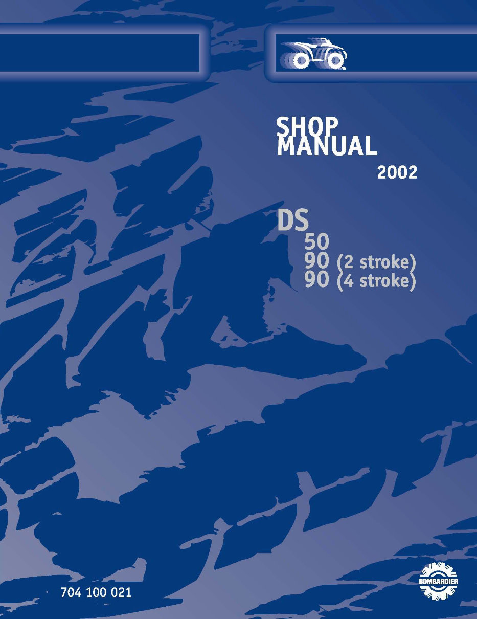
VEHICLE IDENTIFICATION
NUMBER LOCATION
1. V.I.N.
ENGINE IDENTIFICATION
NUMBER LOCATION
2-stroke engine
On 2-stroke engines, the engine identification
number is located on the top side of engine.
4-stroke engine
On 4-stroke engines, the engine identification
number is located on the clutch cover near trans-
mission shifter.
ARRANGEMENT OF THE MANUAL
The manual is divided into 11 major sections:
01 SERVICE TOOLS AND SERVICE PRODUCTS
02 MAINTENANCE
03 ENGINE
04 FUEL SYSTEM
05 ELECTRICAL
06 DRIVE TRAIN
07 STEERING/CONTROL SYSTEMS
08 SUSPENSION
09 BRAKES
10 TECHNICAL DATA
11 WIRING DIAGRAMS
Each section is divided in various subsections, and
again, each subsection has one or more division.
DS50
TM
..................................................... 7557
DS90
TM
..................................................... 7558
DS90 4-stroke .......................................... 7559

VI VMR2002_105_00_02AC.FM
LIST OF ABBREVIATIONS USED IN THIS MANUAL
A ampere
amp ampere
A•h ampere-hour
AC alternate current
BDC bottom dead center
BTDC before top dead center
°C degree Celsius
cm centimeter
DC direct current
°F degree Fahrenheit
fl. oz fluid ounce
ft foot
GRD ground
hal. halogen
I.D. inside diameter
IDI induction discharge ignition
imp. oz imperial ounce
in inch
k kilo (thousand)
kg kilogram
km/h kilometer per hour
kPa kilo pascal
L liter
LH left hand
lb pound
lbf pound (force)
m meter
MAG magneto
Max. maximum
Min. minimum
mL milliliter
mm millimeter
MPH mile per hour
N newton
N.A. not applicable
no. number
00.0 continuity
0.L overload (open circuit)
O.D. outside diameter
OHC Over head camshaft
OPT optional
oz ounce
P/N part number
PSI pound per square inch
PTO power take off
RH Right hand
RPM revolution per minute
TDC top dead center
U.S. oz ounce (United States)
USFD U.S. Forest Service
V volt
Vac volt (alternative current)
INTRODUCTION

VMR2002_105_00_02AC.FM VII
GENERAL INFORMATION
The information and component/system descrip-
tions contained in this manual are correct at time
of publication. Bombardier Inc. however, main-
tains a policy of continuous improvement of its
products without imposing upon itself any obliga-
tion to install them on products previously manu-
factured.
Due to late changes, it may have some differences
between the manufactured product and the de-
scription and/or specifications in this document.
Bombardier Inc. reserves the right at any time to
discontinue or change specifications, designs,
features, models or equipment without incurring
obligation.
ILLUSTRATIONS AND
PROCEDURES
Illustrations and photos show the typical construc-
tion of the different assemblies and, in all cases,
may not reproduce the full detail or exact shape of
the parts shown, however, they represent parts
which have the same or a similar function.
CAUTION: Most components of those vehicles
are built with parts dimensioned in the metric
system. Most fasteners are metric and must
not be replaced by customary fasteners or vice-
versa. Mismatched or incorrect fasteners could
cause damage to the vehicle or possible per-
sonal injury.
As many of the procedures in this manual are in-
terrelated, we suggest, that before undertaking
any task, you read and thoroughly understand the
entire section or subsection in which the proce-
dure is contained.
A number of procedures throughout the book re-
quire the use of special tools. Before commencing
any procedure, be sure that you have on hand all
the tools required, or approved equivalents.
The use of RIGHT and LEFT indications in the text,
always refers to driving position (when sitting on
vehicle).
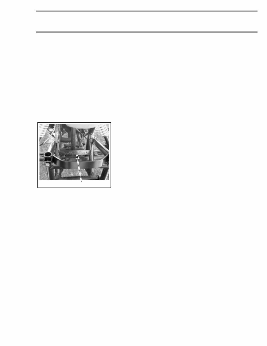
SELF-LOCKING FASTENERS
PROCEDURE
The following describes the most common appli-
cation procedures when working with self-locking
fasteners.
Use a metal brush or a screwtap to clean the hole
properly then use a solvent (Methyl-Chloride), let
act during 30 minutes and wipe off. The solvent
utilization is to ensure the adhesive works properly.
LOCTITE APPLICATION
PROCEDURE
The following describes the most common appli-
cation procedures when working with Loctite
products.
NOTE: Always use proper strength Loctite prod-
uct as recommended in this Shop Manual.
INTRODUCTION
VIII VMR2002_105_00_02AC.FM
Threadlocker
Uncovered Holes (bolts and nuts)
1. Apply here
2. Do not apply
1. Clean threads (bolt and nut) with solvent.
2. Apply Loctite Primer N (P/N 293 800 041) on
threads and allow to dry.
3. Choose proper strength Loctite threadlocker.
4. Fit bolt in the hole.
5. Apply a few drops of threadlocker at proposed
tightened nut engagement area.
6. Position nut and tighten as required.
Blind Holes
1. On threads
2. On threads and at the bottom of hole
1. Clean threads (bolt and hole) with solvent.
2. Apply Loctite Primer N (P/N 293 800 041) on
threads (bolt and nut) and allow to dry for 30 sec-
onds.
3. Choose proper strength Loctite threadlocker.
4. Apply several drops along the threaded hole and
at the bottom of the hole.
5. Apply several drops on bolt threads.
6. Tighten as required.
Stud in Blind Holes
1. On threads
2. On threads and in the hole
3. Onto nut threads
1. Clean threads (stud and hole) with solvent.
2. Apply Loctite Primer N (P/N 293 800 041) on
threads and allow to dry.
3. Put several drops of proper strength Loctite
threadlocker on female threads and in hole.
4. Apply several drops of proper strength Loctite
on stud threads.
5. Install stud.
6. Install cover, etc.
7. Apply drops of proper strength Loctite on un-
covered threads.
8. Tighten nuts as required.
A00A3LA
1
2
INTRODUCTION
VMR2002_105_00_02AC.FM IX
Preassembled Parts
1. Apply here
2. Do not apply
1. Clean bolts and nuts with solvent.
2. Assemble components.
3. Tighten nuts.
4. Apply drops of proper strength Loctite on bolt/nut
contact surfaces.
5. Avoid touching metal with tip of flask.
NOTE: For preventive maintenance on existing
equipment, retighten nuts and apply proper
strength Loctite on bolt/nut contact surfaces.
Adjusting Screw
1. Apply here
2. Plunger
1. Adjust screw to proper setting.
2. Apply drops of proper strength Loctite thread-
locker on screw/body contact surfaces.
3. Avoid touching metal with tip of flask.
NOTE: If it is difficult to readjust, heat screw with
a soldering iron (232°C (450°F)).
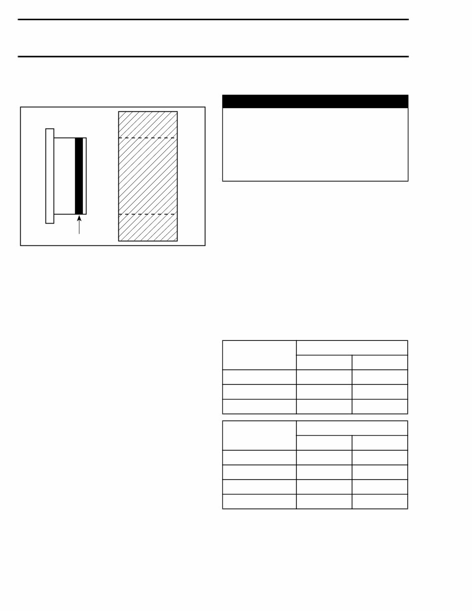
Mounting on Shaft
Mounting with a Press
1. Bearing
2. Proper strength Loctite
3. Shaft
Standard
1. Clean shaft external part and element internal
part.
2. Apply a strip of proper strength Loctite on shaft
circumference at insert or engagement point.
NOTE: Retaining compound is always forced out
when applied on shaft.
3. DO NOT use anti-seize Loctite or any similar
product.
4. No curing period is required.
Mounting in Tandem
1. Apply retaining compound on internal element
bore.
2. Continue to assemble as shown above.
A00A3OA
1
2
A00A3UA
1
2
3
INTRODUCTION
X VMR2002_105_00_02AC.FM
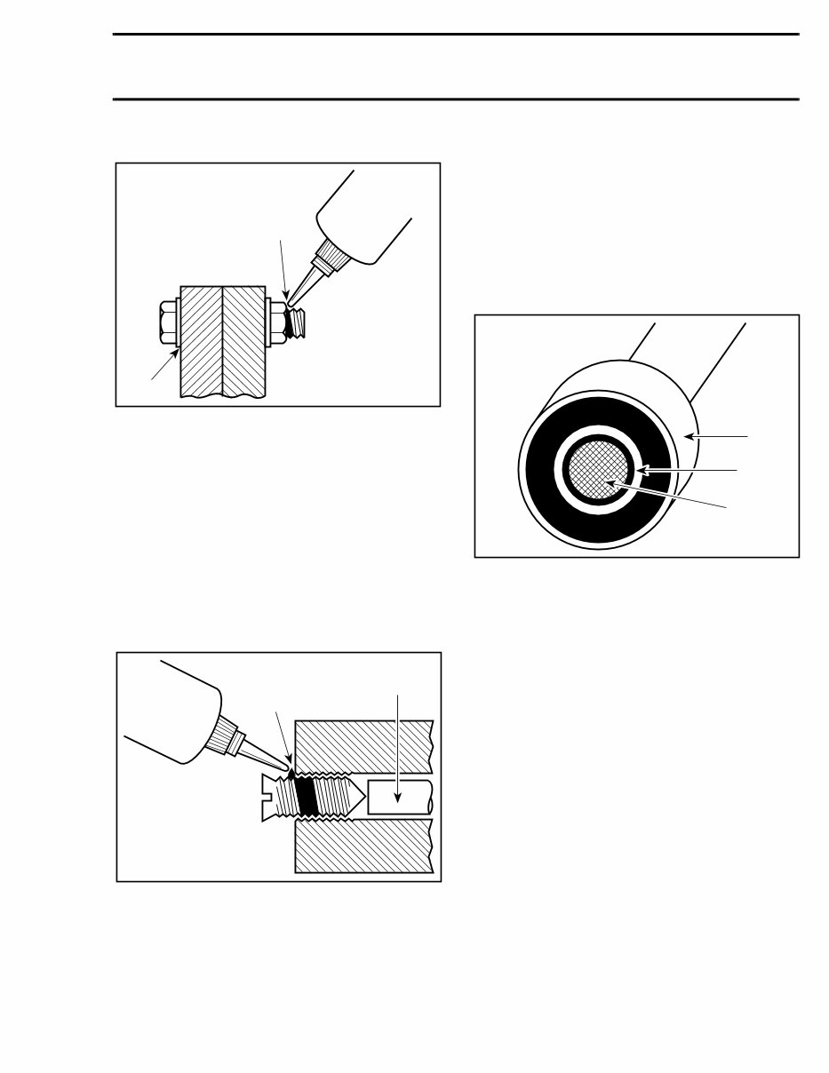
Case-In Components
Metallic Gaskets
1. Proper strength Loctite
1. Clean inner housing diameter and outer gasket
diameter.
2. Spray housing and gasket with Loctite Primer N
(P/N 293 800 041).
3. Apply a strip of proper strength Loctite on lead-
ing edge of outer metallic gasket diameter.
NOTE: Any Loctite product can be used here. A
low strength liquid is recommended as normal
strength and gap are required.
4. Install according to standard procedure.
5. Wipe off surplus.
6. Allow it to cure for 30 minutes.
NOTE: Normally used on worn-out housings to
prevent leaking or sliding.
It is generally not necessary to remove gasket
compound applied on outer gasket diameter.
TIGHTENING TORQUES
Tighten fasteners to torque mentioned in explod-
ed views and text. When they are not specified
refer to following table.The table also gives the
metric conversion.
In order to avoid a poor assembling, tighten
screws and bolts in accordance with the following
procedure:
1. Manually screw all screws, bolts and/or nuts.
2. Apply the half of the recommended torque value.
NOTE: When possible, always apply the torque
on nut.
3. Torque at the recommended torque value.
NOTE: Always torque screws, bolts and/or nuts in
a criss-cross sequence.
* TIGHTENING TORQUES FOR 8.8 GRADE BOLTS AND NUTS
A00A3VA 1
WARNING
Torque wrench tightening specifications
must strictly be adhered to.
Locking devices (ex.: locking tabs, elastic
stop nuts, self-locking fasteners, etc.) must
be installed or replaced with new ones where
specified. If the efficiency of a locking device
is impaired, it must be renewed.
BOLT OR NUT
SIZE
TIGHTENING TORQUE*
N•m lbf•in
M4 2 18
M5 4 35
M6 10 89
BOLT OR NUT
SIZE
TIGHTENING TORQUE*
N•m lbf•ft
M8 23 17
M10 48 35
M12 80 59
M14 135 100
INTRODUCTION
You're Reading a Preview
What's Included?
Fast Download Speeds
Online & Offline Access
Access PDF Contents & Bookmarks
Full Search Facility
Print one or all pages of your manual
$39.99
Viewed 27 Times Today


Secure transaction
What's Included?
Fast Download Speeds
Online & Offline Access
Access PDF Contents & Bookmarks
Full Search Facility
Print one or all pages of your manual
$39.99
- Get comprehensive guidance for maintaining and repairing your 2002 Bombardier DS90 2-Stroke ATV with this detailed Service & Repair Manual.
- Includes in-depth instructions for maintenance, troubleshooting, and repairs, along with clear illustrations and exploded-view diagrams.
- Recommended for professional mechanics and DIY enthusiasts to ensure optimal performance and longevity of the ATV.
- Covers a wide range of tasks including engine servicing, carburetor adjustments, electrical system diagnostics, and chassis maintenance.
- Accessible in digital format for easy retrieval and efficient navigation on various devices such as PCs, tablets, and smartphones.
- Essential for keeping your 2002 Bombardier DS90 2-Stroke ATV in top condition for off-road adventures.
- Printable: Yes
- Language: English
- Compatibility: Compatible across a wide range of devices including PCs, Macs, smartphones, and tablets.
- Requirements: A PDF reader like Adobe Reader (free)


