

2015 Arctic Cat Wildcat Sport Service & Repair Manual
What's Included?
Fast Download Speeds
Online & Offline Access
Access PDF Contents & Bookmarks
Full Search Facility
Print one or all pages of your manual

SERVICE MANUAL
SERVICE MANUAL
SERVICE MANUAL
www.arcticcat.com
WILDCAT SPORT

FOREWORD
This Arctic Cat Service Manual contains service, maintenance, and troubleshooting information for the 2015 Arctic
Cat Wildcat Sport. The complete manual is designed to aid service personnel in service-oriented applications.
This manual is divided into sections. Each section covers a specific vehicle component or system and, in addition to the
standard service procedures, includes disassembling, inspecting, and assembling instructions. When using this manual
as a guide, the technician should use discretion as to how much disassembly is needed to correct any given condition.
The service technician should become familiar with the operation and construction of each component or system by
carefully studying this manual. This manual will assist the service technician in becoming more aware of and efficient
with servicing procedures. Such efficiency not only helps build consumer confidence but also saves time and labor.
All Arctic Cat publications and decals display the words Warning, Caution, Note, and At This Point to emphasize
important information. The symbol ! WARNING identifies personal safety-related information. Be sure to fol-
low the directive because it deals with the possibility of serious personal injury or even death. A CAUTION identi-
fies unsafe practices which may result in vehicle-related damage. Follow the directive because it deals with the
possibility of damaging part or parts of the vehicle. The symbol NOTE: identifies supplementary information wor-
thy of particular attention. The symbol AT THIS POINT directs the technician to certain and specific proce-
dures to promote efficiency and to improve clarity.
At the time of publication, all information, photographs, and illustrations were technically correct. Some photographs
used in this manual are used for clarity purposes only and are not designed to depict actual conditions. Because Arctic
Cat Inc. constantly refines and improves its products, no retroactive obligation is incurred.
All materials and specifications are subject to change without notice.
Keep this manual accessible in the shop area for reference.
Product Service and
Warranty Department
Arctic Cat Inc.
© 2014 Arctic Cat Inc. November 2014
®™ Trademarks of Arctic Cat Inc., Thief River Falls, MN 56701

1
TABLE OF CONTENTS
General Information .............................................................. 2
General Specifications ............................................................... 2
Torque Specifications................................................................. 3
Torque Conversions (ft-lb/N-m) .................................................. 4
Drive Belt Break-In Procedure ................................................... 4
Gasoline - Oil - Lubricant ........................................................... 4
Genuine Parts ............................................................................ 5
Preparation For Storage ............................................................ 5
Preparation After Storage .......................................................... 5
Periodic Maintenance/Tune-Up ............................................ 6
Periodic Maintenance Chart ...................................................... 6
Lubrication Points ...................................................................... 7
Air Filter ..................................................................................... 7
Testing Engine Compression ..................................................... 7
Spark Plugs ............................................................................... 8
Muffler/Spark Arrester................................................................ 8
Engine Oil - Filter ....................................................................... 9
Front Differential - Transaxle Lubricant ...................................... 9
Nuts/Bolts/Cap Screws ............................................................ 10
Headlight/Taillight-Brakelight.................................................... 10
Hydraulic Brake System........................................................... 13
Burnishing Brake Pads ............................................................ 14
Replacing V-Belt ...................................................................... 14
Steering/Frame/Controls .................................................... 17
Front Bumper ........................................................................... 17
Hood/Grille/Storage Box .......................................................... 18
Body Panels ............................................................................. 19
Center Console ........................................................................ 24
Rack and Pinion Assembly ...................................................... 24
Steering Wheel ........................................................................ 26
Electronic Power Steering (EPS) ............................................. 27
Steering Shaft .......................................................................... 28
Steering Knuckles .................................................................... 30
Checking/Adjusting Front Wheel Alignment ............................. 32
Accelerator Pedal ..................................................................... 32
Shift Lever ................................................................................ 33
Shift Cable ............................................................................... 34
LCD Gauge .............................................................................. 35
Exhaust System....................................................................... 36
Cargo Box ................................................................................ 36
Seats........................................................................................ 37
Doors ....................................................................................... 37
Floor......................................................................................... 38
Troubleshooting ....................................................................... 39
Engine .................................................................................. 40
Troubleshooting ....................................................................... 41
Removing Engine .................................................................... 43
Top-Side Components ............................................................. 48
Removing Top-Side Components ............................................ 48
Servicing Top-Side Components ............................................. 51
Bottom-Side Components........................................................ 62
Removing Bottom-Side Components ...................................... 62
Servicing Bottom-Side Components ........................................ 66
Installing Bottom-Side Components ........................................ 68
Servicing Left-Side Components ............................................. 71
Installing Engine ...................................................................... 75
Fuel/Lubrication/Cooling ............................................................. 80
Throttle Body ........................................................................... 80
Gas Tank.................................................................................. 82
Gas/Vent Hoses ....................................................................... 83
Oil Filter/Oil Pump.................................................................... 83
Oil Cooler ................................................................................. 83
Oil Flow Chart .......................................................................... 84
Liquid Cooling System ............................................................. 85
Radiator ................................................................................... 85
Thermostat .............................................................................. 87
Fan........................................................................................... 88
Water Pump ............................................................................. 88
Troubleshooting ....................................................................... 90
Electrical System ................................................................ 91
Battery ..................................................................................... 91
Accessory Receptacle/Connector ........................................... 92
Brakelight Switch ..................................................................... 92
Engine Coolant Temperature (ECT) Sensor ............................ 93
Fan Motor................................................................................. 93
Power Distribution Module (PDM) ............................................ 94
Ignition Coils ............................................................................ 94
EFI Sensors/Components........................................................ 95
Speed Sensor .......................................................................... 96
RPM Limiter ............................................................................. 97
Electronic Power Steering (EPS) ............................................. 97
Ignition Switch.......................................................................... 98
Headlight Switch ...................................................................... 99
Drive Select Switch .................................................................. 99
Reverse Override Switch ......................................................... 99
Front Drive Actuator ............................................................... 100
Stator Coil .............................................................................. 100
Starter Motor.......................................................................... 100
Starter Relay .......................................................................... 101
Engine Control Module (ECM) ............................................... 101
Fuel Pump/Fuel Level Sensor................................................ 102
Regulator/Rectifier ................................................................. 103
Headlights .............................................................................. 103
Taillight-Brakelight .................................................................. 104
Tilt Sensor.............................................................................. 104
Throttle Position Sensor (TPS) .............................................. 105
EFI Diagnostic System .......................................................... 105
Troubleshooting ..................................................................... 110
Drive and Brake Systems................................................. 111
Front Drive Actuator ............................................................... 111
Front Differential .................................................................... 112
Drive Axles............................................................................. 125
Transaxle ............................................................................... 127
Driveshaft/Carrier Bearing ..................................................... 142
Hub ........................................................................................ 145
Hydraulic Brake Caliper (Front) ............................................. 147
Master Cylinder Assembly ..................................................... 153
Troubleshooting ..................................................................... 154
Suspension ....................................................................... 155
Shock Absorbers ................................................................... 155
Front A-Arms ......................................................................... 159
Rear A Arms .......................................................................... 162
Rear Sway Bar ....................................................................... 165
Wheels and Tires ................................................................... 165
Troubleshooting ..................................................................... 166

2
General Information
NOTE: Some photographs and illustrations used in
this manual are used for clarity purposes only and are
not designed to depict actual conditions.
NOTE: Whenever a part is worn excessively, cracked,
or damaged in any way, replacement is necessary.
NOTE: Never reuse a lock nut. Once a lock nut has
been removed, it must be replaced with a new lock nut.
General Specifications
* Visible at plug threads.
Specifications subject to change without notice.
CHASSIS
Dry Weight (approx) 478 kg (1054 lb) - Sport/XT
487 kg (1074 lb) - Limited
ROPS Tested Curb Weight 845 kg (1864 lb)
Length (overall) 280.6 cm (110.5 in.)
Height (overall) 163.3 cm (64.3 in.)
Width (overall) 152 cm (60 in.)
Tire Size 26 x 9-12R (Front)
26 x 11-12R (Rear)
Tire Inflation Pressure 0.98 kg/cm² (14 psi)
MISCELLANY
Spark Plug Type NGK CR8EB
Spark Plug Gap 0.6-0.8 mm (0.023-0.031 in.)
Gas Tank Capacity 28 L (7.4 U.S. gal.)
Coolant Capacity 3.1 L (3.2 U.S. qt)
Front Differential Capacity 200 ml (6.8 fl oz)*
Transaxle Capacity 1.2 L (1.2 U.S. qt)*
Engine Oil Capacity 2.8 L (3.0 U.S. qt) - Change
3.34 L (3.4 U.S. qt) - Overhaul
Gasoline (recommended) 87 Octane Regular Unleaded
Engine Oil (recommended) Arctic Cat ACX All Weather
Synthetic
Front Differential Lubricant SAE Approved 80W-90 Hyp-
oid
Transaxle Lubricant Arctic Cat Synthetic Transaxle
Fluid
Belt Width 31.3 mm (1.23”)
Brake Fluid DOT 4
Taillight/Brakelight High Intensity LED
Headlight Halogen
COOLING SYSTEM
Cooling Fan On 203° F (95° C)
Cooling Fan Off 194° F (90° C)
ELECTRICAL SYSTEM
Spark Plug Cap 5000 ohms
Ignition Coil Resistance(primary) Less than 1 ohm
Ignition Coil Primary Voltage Battery Voltage
Stator Coil (crankshaft position sensor)
Resistance(AC generator)
100-150 ohms
Less than 1 ohm
Crankshaft Position Sensor 1.5 AC Volts or more
AC Generator Output (no load) 65 AC volts @ 4000 RPM
Ignition Timing 10° BTDC @ 1500 RPM
VALVES AND GUIDES
Valve Face Diameter (intake)
(exhaust)
31.6 mm
27.9 mm
Valve/Tappet Clearance (intake)
(cold engine) (max) (exhaust)
0.16 mm
0.22 mm
Valve Guide/Stem (intake)
Clearance (max) (exhaust)
0.08 mm
0.10 mm
Valve Guide Inside Diameter (max) 4.532 mm
Valve Head Thickness (min) 2.3 mm
Valve Seat Angle 45° +15’/+30’
Valve Spring Free Length (min) 38.7 mm
Valve Spring Tension @ 31.5 mm 19.0 kg (42 lb)
CAMSHAFT AND CYLINDER HEAD
Cam Lobe Height (min) 36.5 mm
Camshaft Journal Oil Clearance (max) 0.07 mm
Camshaft Journal Holder(right & center)
Inside Diameter (left)
21.94-22.04 mm
17.44-17.48 mm
Camshaft Journal Outside(right & center)
Diameter (left)
21.96-21.98 mm
17.48-17.53 mm
Camshaft Runout (max) 0.05 mm
Cylinder Head/Cover Distortion (max) 0.05 mm
CYLINDER, PISTON, AND RINGS
Piston/Cylinder Clearance 0.14mm
Cylinder Bore (max) 76.965 mm
Piston Diameter 10 mm from Skirt End 76.825 mm
Piston Ring Free End Gap (min) (1st/2nd) 12.5 mm
Bore x Stroke 76.9 x 75.3 mm
Cylinder Trueness (max) 0.05 mm
Piston Ring End Gap (1st/2nd)
- Installed (max) (oil)
0.65 mm
0.85 mm
Piston Ring to Groove Clearance (max) 0.1 mm
Piston Ring Groove Width (1st/2nd)
(oil)
1.202-1.204 mm
2.501-2.503 mm
Piston Ring Thickness (1st/2nd) 1.170-1.195 mm
Piston Pin Bore (max) 18.018 mm
Piston Pin Outside Diameter (min) 17.984 mm
CRANKSHAFT
Connecting Rod (small end bore) (max) 18.044 mm
Crankshaft Runout (max) 0.03 mm

3
Torque Specifications
*w/Oil **w/Red Loctite #271 ***w/Green Loctite #270
****w/“Patch-Lock” *****w/Anti-Seize
Torque (ft-lb) Tolerance
0-15 ±20%
16-39 ±15%
40+ ±10%
EXHAUST COMPONENTS
Part Part Bolted To
Torque
ft-lb N-m
Exhaust Pipe Flange Engine 8 10
Spark Arrester Muffler 6 8
Heat Shield Frame 48 in.-lb 6
Heat Shield Manifold 10 14
O2 Sensor Manifold 20 27
BRAKE COMPONENTS
Brake Disc Hub 15 20
Brake Hose Caliper 20 27
Brake Hose Master Cylinder 20 27
Brake Hose Frame 8 11
Master Cylinder Frame 25 34
Rear Caliper Knuckle 20 27
Front Caliper**** Knuckle 35 47
SUSPENSION COMPONENTS (Front)
A-Arm (Upper) Frame 42 57
A-Arm (Lower) Frame 40 54
Knuckle Ball Joint 35 48
Knuckle Tie Rod End 30 40
Shock Absorber Frame 35 48
Shock Absorber A-Arm 35 48
A-Arm**** Knuckle 35 48
SUSPENSION COMPONENTS (Rear)
Sway Bar Mount Frame 35 48
Sway Bar Sway Bar Link 20 27
Sway Bar Link A-Arm 20 27
A-Arm Frame 35 48
Shock Absorber (Lower) A-Arm 35 48
Shock Absorber (Upper) Frame 35 48
Knuckle A-Arm 35 48
STEERING COMPONENTS
Steering Wheel Steering Shaft 25 34
Rack and Pinion Assembly Frame 25 34
Rack and Pinion Bracket Frame 25 34
Tie Rod* Rack and Pinion Assembly 37 50
Jam Nut Tie Rod 25 34
Tilt Steering Link Frame 10 14
Tilt Steering Frame 20 27
Intermediate Shaft Rack and Pinion 25 34
Intermediate Shaft Shaft Adjuster 25 34
EPS Mounting Bracket EPS Assembly 35 48
EPS Assembly Frame 20 27
CHASSIS/ROPS ASSEMBLY
Door Latch Bracket Frame 8 11
Door Hinge Frame 20 27
Shift Lever Shift Mount Bracket 20 27
Shift Cable Shift Axle Arm 8 11
Front ROPS Tube Frame 40 54
Front ROPS Tube Rear ROPS Tube 40 54
Rear ROPS Tube Frame 40 54
Cargo Box Frame 5 7
Seat Belt Retractor Frame 60 81
Seat Belt Shoulder ROPS Hoop 35 48
Seat Belt Buckle Frame 60 81
Seat Belt Anchor Frame 60 81
Accelerator Pedal Bracket Splash Panel 10 14
Accelerator Pedal Accelerator Pedal Bracket 20 27
Throttle Cable Throttle Body 8 11
Brake Pedal Frame 20 27
Front Bumper Frame 20 27
DRIVE TRAIN COMPONENTS
Part Part Bolted To
Torque
ft-lb N-m
Engine/Transaxle Mounting
Bracket*****
Transaxle 75 102
Front Differential Differential Bracket 38 52
Carrier Bearing Bearing Bracket 35 48
Carrier Bearing Bracket Frame 20 27
Carrier Bearing Set Screw** Front Shaft 6 8
Pinion Housing Differential Housing 23 31
Differential Housing Cover*** Differential Housing 23 31
Hub Axle/Knuckle 200 270
Detent Plug Transaxle 20 27
Speed Sensor Transaxle 10 14
Oil Drain Plug Front Differential 45 in.-lb 5
Oil Fill Plug Front Differential 16 22
Drain Plug Transaxle 18 24
Fill Plug Transaxle 18 24
Wheel (steel wheel) Hub (20 ft-lb increments) 40 54
Wheel (aluminum wheel w/
black nuts)
Hub (20 ft-lb increments) 60 81
Wheel (aluminum wheel w
chrome nuts))
Hub (20 ft-lb increments) 80 108
ENGINE
Front Rubber Mount Engine Mounting Bracket 20 27
Front Rubber Mount Frame 25 34
Transaxle Rubber Mount Frame 20 27
Front Engine Mount Engine 35 48
Rear Engine Mount Frame 40 54
Adjuster Nut Engine/Transaxle Mounting Bracket 15 20
Transaxle Mounting Bracket Transaxle 37 50
Transaxle Mounting Bracket Rubber Mount 25 34
Crankcase Half (6 mm) Crankcase Half 7 9.5
Crankcase Half (8 mm) Crankcase Half 21 28
Cylinder Head (Cap Screw)* Crankcase (step 1)
(step 2)
(final)
22
29
36
29
39
49
Cylinder Head Cover Cylinder Head 7 9.5
Driven Clutch Input Shaft 35 48
Drive Clutch Crankshaft 60 81
Magneto Cover Crankcase 7 9.5
Tappet Cover Valve Cover 7 9.5
Oil Pump Crankcase 8 10
Rotor/Flywheel Crankshaft 60 81
Cam Sprocket** Camshaft 7 9.5
Inner Clutch Cover Engine 8 11
Camshaft Holder* Cylinder Head 7 9.5
Shifter Housing Crankcase 8 11
Starter Motor Crankcase 8 11
Outer Clutch Cover Inner Cover 5 5.5
Intake Boot Clamp Intake Boot 30 in.-lb 3.4
Starter One-Way Clutch** Rotor/Flywheel 20 27
Fuel Rail Engine 6 8
Air Filter Housing Frame 5 7
Ground Wire Engine 7 9.5
Stator Coil Magneto Cover 11 15
Oil Drain Plug Engine 20 27
Drain Plug Clutch Cover 50 in.-lb 5.5
Cam Chain Tensioner Cylinder Head 15 20
Connecting Rod Connecting Rod (step 1)
(step 2)
(final)
22
36
45
29
49
60
Oil Crossover Tube Crankcase 13.5 18
Cylinder Head (Side) Crankcase 7 9.5
Oil Filter Union Crankcase 20 27
Phase Plate Sprocket 7 9.5
Timing Inspection Plug Magneto Cover 10 17
Magneto Plug Magneto Cover 8 11
Oil Hose Fitting Crankcase 25 34
PTO-Side Cover Crankcase 7 9.5
Tensioner Cap Tensioner 15 20
Upper Chain Guide Cylinder Head 7 9.5
Oil Cooler Hose Oil Cooler/Engine 35 in.-lb 4
Coolant Hose Coolant Pipe 40 in.-lb 4.5
Coolant Hose Water Pump/Cylinder 35 in.-lb 4
Bypass Hose Thermostat Coolant Pipe 15 in.-lb 1.7
4
Torque Conversions
(ft-lb/N-m)
Drive Belt Break-In
Procedure
New drive belts require a break-in period of approximately
25 miles. During this period, drive the vehicle for 25 miles
at 3/4 throttle or less while varying throttle position (but
not exceeding 40 mph). By varying throttle position, the
exposed cord on the side of a new belt will be conditioned
allowing the drive belt to gain its optimum flexibility and
will extend drive belt life.
Gasoline - Oil - Lubricant
RECOMMENDED GASOLINE
The recommended gasoline to use is 87 minimum octane
regular unleaded. In many areas, oxygenates are added to
the gasoline. Oxygenated gasolines containing up to 10%
ethanol or 5% methane are acceptable gasolines.
When using ethanol blended gasoline, it is not necessary to
add a gasoline antifreeze since ethanol will prevent the
accumulation of moisture in the fuel system.
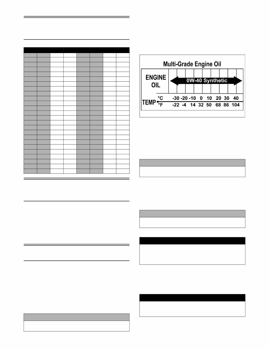
RECOMMENDED ENGINE OIL
The recommended oil to use is Arctic Cat ACX All
Weather synthetic engine oil, which has been specifically
formulated for use in this Arctic Cat engine. Although
Arctic Cat ACX All Weather synthetic engine oil is the
only oil recommended for use in this engine, use of any
API certified SM 0W-40 oil is acceptable.
OILCHARTJ
RECOMMENDED FRONT
DIFFERENTIAL LUBRICANT
The recommended lubricant is Arctic Cat Gear Lube or an
equivalent gear lube which is SAE approved 80W-90 hypoid.
This lubricant meets all of the lubrication requirements of the
Arctic Cat vehicle front differential and rear drive.
RECOMMENDED TRANSAXLE
LUBRICANT
The recommended transaxle lubricant is Arctic Cat Syn-
thetic Transaxle Fluid. This lubricant meets all of the lubri-
cation requirements of this vehicle.
FILLING GAS TANK
Since gasoline expands as its temperature rises, the gas
tank must be filled to its specified capacity only. Expan-
sion room must be maintained in the tank particularly if
the tank is filled with cold gasoline and then moved to a
warm area.
ft-lb N-m ft-lb N-m ft-lb N-m ft-lb N-m
1 1.4 26 35.4 51 69.4 76 103.4
2 2.7 27 36.7 52 70.7 77 104.7
3 4.1 28 38.1 53 72.1 78 106.1
4 5.4 29 39.4 54 73.4 79 107.4
5 6.8 30 40.8 55 74.8 80 108.8
6 8.2 31 42.2 56 76.2 81 110.2
7 9.5 32 43.5 57 77.5 82 111.5
8 10.9 33 44.9 58 78.9 83 112.9
9 12.2 34 46.2 59 80.2 84 114.2
10 13.6 35 47.6 60 81.6 85 115.6
11 15 36 49 61 83 86 117
12 16.3 37 50.3 62 84.3 87 118.3
13 17.7 38 51.7 63 85.7 88 119.7
14 19 39 53 64 87 89 121
15 20.4 40 54.4 65 88.4 90 122.4
16 21.8 41 55.8 66 89.8 91 123.8
17 23.1 42 57.1 67 91.1 92 125.1
18 24.5 43 58.5 68 92.5 93 126.5
19 25.8 44 59.8 69 93.8 94 127.8
20 27.2 45 61.2 70 95.2 95 129.2
21 28.6 46 62.6 71 96.6 96 130.6
22 29.9 47 63.9 72 97.9 97 131.9
23 31.3 48 65.3 73 99.3 98 133.3
24 32.6 49 66.6 74 100.6 99 134.6
25 34 50 68 75 102 100 136
CAUTION
Do not use white gas. Only Arctic Cat approved gaso-
line additives should be used.
CAUTION
Any lubricant used in place of the recommended lubri-
cant could cause serious front differential damage.
CAUTION
Any lubricant used in place of the recommended lubri-
cant could cause serious transaxle damage.
! WARNING
Always fill the gas tank in a well-ventilated area. Never
add fuel to the gas tank near any open flames or with
the engine running. DO NOT SMOKE while filling the
gas tank.
! WARNING
Do not overflow gasoline when filling the gas tank. A
fire hazard could materialize. Always allow the engine to
cool before filling the gas tank.

5
Tighten the gas tank cap securely after filling the tank.
Genuine Parts
When replacement of parts is necessary, use only genuine Arc-
tic Cat parts. They are precision-made to ensure high quality
and correct fit. Refer to the appropriate Illustrated Parts Man-
ual for the correct part number, quantity, and description.
Preparation For Storage
1. Clean the seat cushion (cover and base) with a damp
cloth and allow it to dry.
2. Clean the vehicle thoroughly by washing dirt, oil,
grass, and other foreign matter from the entire vehicle.
Allow it to dry thoroughly. DO NOT get water into
any part of the engine or air intake.
3. Either drain the gas tank or add Fuel Stabilizer to the
gas in the gas tank. Remove the air filter housing
cover and air filter. Start the engine and allow it to
idle. Using Arctic Cat Engine Storage Preserver, rap-
idly inject the preserver into the air filter opening for a
period of 10 to 20 seconds; then stop the engine.
Install the air filter and housing cover.
4. Plug the exhaust hole in the exhaust system with a
clean cloth.
5. Apply light oil to the plungers of the shock absorbers.
6. Tighten all nuts, bolts, cap screws, and screws. Make
sure rivets holding components together are tight.
Replace all loose rivets. Care must be taken that all
calibrated nuts, cap screws, and bolts are tightened to
specifications.
7. Fill the cooling system to the bottom of the stand pipe
in the radiator neck with properly mixed coolant.
8. Disconnect the battery cables; then remove the bat-
tery, clean the battery posts and cables, and store in a
clean, dry area.
9. Store the vehicle indoors in a level position.
Preparation After
Storage
Taking the vehicle out of storage and correctly preparing it
will assure many miles and hours of trouble-free riding.
1. Clean the vehicle thoroughly.
2. Clean the engine. Remove the cloth from the exhaust
system.
3. Check all control wires and cables for signs of wear or
fraying. Replace if necessary.
4. Change the engine oil and filter.
5. Check the coolant level and add properly mixed cool-
ant as necessary.
6. Charge the battery; then install. Connect the battery
cables.
7. Check the entire brake systems (fluid level, pads,
etc.), all controls, headlights, taillight, brakelight, and
headlight aim; adjust or replace as necessary.
8. Tighten all nuts, bolts, cap screws, and screws making
sure all calibrated nuts, cap screws, and bolts are tight-
ened to specifications.
9. Check tire pressure. Inflate to recommended pressure
as necessary.
10. Make sure the steering moves freely and does not
bind.
11. Check the spark plugs. Clean or replace as necessary.
! WARNING
Do not over-fill the gas tank.
CAUTION
Prior to storing the vehicle, it must be properly serviced
to prevent rusting and component deterioration.
CAUTION
If the interior of the air filter housing is dirty, clean the
area before starting the engine.
CAUTION
Avoid storing outside in direct sunlight and avoid using
a plastic cover as moisture will collect on the vehicle
causing rusting.
CAUTION
The ignition switch must be in the OFF position prior to
installing the battery or damage may occur to the igni-
tion system.
CAUTION
Connect the positive battery cable first; then the nega-
tive.

6
Periodic Maintenance/
Tune-Up
This section has been organized into sub-sections showing
common maintenance procedures.
SPECIAL TOOLS
A number of special tools must be available to the techni-
cian when performing service procedures in this section.
Refer to the current Special Tools Catalog for the appropri-
ate tool description.
NOTE: Special tools are available from the Arctic
Cat Service Department.
Periodic Maintenance
Chart
A = Adjust I = Inspect C = Clean L = Lubricate R = Replace T = Tighten
* Service/Inspect more frequently when operating in adverse conditions.
** When using an API certified SM 0W-40 oil.
*** When using Arctic Cat ACX All Weather synthetic oil, oil change and strainer inspection interval can be increased to every
1,000 miles or every year.
Description p/n
Compression Tester Kit 0444-213
Oil Filter Wrench 0644-389
Timing Light 0644-296
Item
Initial Service After
Break-In (First
Month or 100 Miles)
Daily
Monthly
(100 Miles)
Every 3
Months (300
Miles)
Every 6
Months (500
Miles)
Annually
(1500 Miles)
As
Needed
Battery I I C
Fuses I R
Air Filter I I* R
Valve/Tappet Clearance I I A
Engine Compression I
Spark Plugs I I I R (4000 Mi
or 18 Mo)
Muffler/Spark Arrester C R
Gas Hoses I I R (2 Yrs)
Throttle Cable Ends/Accelerator Pedal Pivot I I C-L A-R
Engine Oil/Filter R R*/R**/R*** A/R
Front Differential Lubricant R I R
Transaxle Lubricant R I R
(2000Mi)
Tires/Air Pressure I I R
Steering Components I I I R
V-Belt I l R
Suspension (Ball joint boots, drive axle boots
front and rear, tie rods, differential and rear
drive bellows)
I I R
Nuts/Bolts/Cap Screws T T A
Ignition Timing I
Headlight/Taillight-Brakelight I I R
Switches I I R
Shift Lever I A-L
Gauge/Indicators I I R
Frame/Welds I I l
Electrical Connections l C
Complete Brake System I I
Brake Pads I I* R
Brake Fluid I I R (2 Yrs)
Brake Hoses I I R (4 Yrs)
Coolant/Cooling System I I R (2 Yrs)
Wheel Lug Nuts T T
7
Lubrication Points
It is advisable to lubricate certain components periodically
to ensure free movement. Apply light oil to the compo-
nents using the following list as reference.
A. Accelerator Pedal Pivot/Cable Ends
B. Brake Pedal Pivot
C. Shift Cable
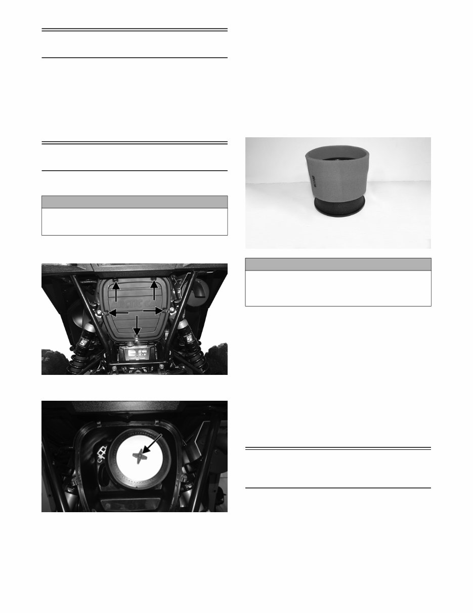
Air Filter
CLEANING AND INSPECTING FILTER
1. Unsnap the five fasteners securing the air filter hous-
ing cover and remove the cover.
WS025A
2. Remove the air filter knob; then remove the air filter.
WT176A
NOTE: Do not attempt to remove the inner foam
from the wire mesh. It is part of the filter frame.
3. Fill a wash pan larger than the filter with a non-flam-
mable cleaning solvent; then dip the inner filter and
outer foam medium in the solvent and wash them.
NOTE: Foam Filter Cleaner and Foam Filter Oil are
available from Arctic Cat.
4. Dry both filter components.
5. Put the foam filter in a plastic bag; then pour in air fil-
ter oil and work the filter.
NOTE: Apply oil to the inner filter; then carefully
squeeze excessive oil from the filter element. Do not
twist foam to remove oil.
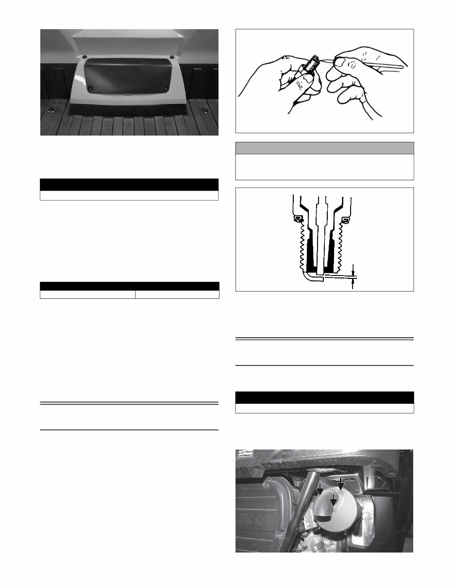
6. Attach the foam filter to the inner filter screen.
WT179
7. Clean any dirt or debris from inside the air cleaner. Be
sure no dirt enters the throttle body.
8. Place the foam filter onto the filter frame; then install
the air filter on the filter rod and install the filter knob.
Tighten securely.
9. Install the air filter housing cover and secure with the
retaining clips.
CHECKING AND CLEANING DRAINS
1. Inspect the drain beneath the main housing for debris
or liquid. Remove and clean the drain bulb if contami-
nated.
2. Wipe any accumulation of oil or gas from the filter
housing and drain.
Testing Engine
Compression
NOTE: The engine should be warm (operating tem-
perature) and the battery fully charged for an accurate
compression test.
NOTE: The access panel must be removed for this
procedure.
CAUTION
Failure to inspect the air filter frequently if the vehicle is
used in dusty, wet, or muddy conditions can damage
the engine.
CAUTION
A torn air filter can cause damage to the vehicle engine. Dirt
and dust may get inside the engine if the element is torn.
Carefully examine the element for tears before and after
cleaning it. Replace the element with a new one if it is torn.
8
WT021
1. Remove the spark plug wires from the spark plugs.
2. Using compressed air, blow any debris from around
the spark plugs.
3. Remove the spark plugs; then attach the spark plug wires
to the plugs and ground the plugs on the cylinder heads
well away from the spark plug holes.
4. Attach the Compression Tester Kit.
5. While holding the throttle in the full-open position, crank
the engine over with the electric starter until the gauge
stops climbing (five to 10 compression strokes). Compres-
sion should be as shown in the chart.
6. If compression is abnormally low, verify the following:
A. Starter cranks engine over (normal speed).
B. Gauge is functioning properly.
C. Throttle in the full-open position.
D. Valve/tappet clearance correct.
E. Engine warmed up.
7. If compression is still low, check for blown cylinder head
gasket, valve leakage, or worn piston rings or cylinder
(see Engine – Servicing Top-Side Components).
Spark Plugs
A light brown insulator indicates the plug is correct. A white or
dark insulator indicates that the engine may need to be ser-
viced. To maintain a hot, strong spark, keep the plug free of
carbon. Adjust the gap to 0.6-0.8 mm (0.023-0.031 in.).
ATV-0051
ATV-0052
When installing a spark plug, be sure to tighten it securely. A
new spark plug should be tightened 1/2 turn once the washer
contacts the cylinder head. A used spark plug should be tight-
ened 1/8-1/4 turn once the washer contacts the cylinder head.
Muffler/Spark Arrester
Clean the spark arrester using the following procedure.
1. Remove the spark arrester screen; then using a suit-
able brush, clean the carbon deposits from the screen
taking care not to damage the screen.
WS035A
! WARNING
Always wear safety glasses when using compressed air.
PSI (WOT)
Cylinder #1/Cylinder #2 185
CAUTION
Before removing a spark plug, be sure to clean the area
around the spark plug. Dirt could enter engine when
removing or installing the spark plug.
! WARNING
Wait until the muffler cools to avoid burns.
You're Reading a Preview
What's Included?
Fast Download Speeds
Online & Offline Access
Access PDF Contents & Bookmarks
Full Search Facility
Print one or all pages of your manual
$39.99
Viewed 27 Times Today


Secure transaction
What's Included?
Fast Download Speeds
Online & Offline Access
Access PDF Contents & Bookmarks
Full Search Facility
Print one or all pages of your manual
$39.99
- The 2015 Arctic Cat Wildcat Sport Service & Repair Manual is a comprehensive resource for troubleshooting and replacing parts in your UTV.
- It includes step-by-step instructions, clear images, and exploded-view illustrations provided by the manufacturer.
- Regular maintenance is essential for the durability of your UTV, and this manual offers the manufacturer's recommended troubleshooting charts and replacement procedures.
- By using this manual, both professional mechanics and DIY enthusiasts can save on repairs, increase the reliability of their UTV, and reduce reliance on repair shops.
- Conveniently available in .pdf format, this manual is printable and can be accessed on various electronic devices such as PC, Mac, smartphones, and tablets.
- It is compatible with Adobe Reader, and users have the option to print physical copies if preferred.


