

2012 Arctic Cat Prowler hdx UTV/ATV service & repair manual
What's Included?
Fast Download Speeds
Online & Offline Access
Access PDF Contents & Bookmarks
Full Search Facility
Print one or all pages of your manual
TM
SHARE OUR PASSION.
T
O RO RO V V
Manual n Service M S S n v u c a a r M u l a a i e e M S S M n a a r v c ervice S S
T T XT XT X X er X ler X Prow Prowl X P P l T e o o owle X Prowler XT
X X X TX TX XT XT X X er X ler X Prow Prowl X X P P l T e o X X o owle X X X Prowler X
Z TZ Z Z TZ XT X XT X X r X er X e ler X Prow w Prowl X P P l TZ Z TZ e o o owle X Prowler X
TABLE OF CONTENTS
FOREWORD
1. General Information/Specifications
2. Periodic Maintenance/Tune-Up
3. Engine/Transmission
4. Fuel/Lubrication/Cooling
5. Electrical System
6. Drive System
7. Suspension
8. Steering/Frame/Controls
1
2
3
4
5
6
7
8

1-1
1
SECTION 1 - GENERAL INFORMATION
TABLE OF CONTENTS
General Specifications ............................................ 1-2
Torque Specifications .............................................. 1-3
Torque Conversions (ft-lb/N-m) ............................... 1-4
Break-In Procedure ................................................. 1-4
Gasoline - Oil - Lubricant ........................................ 1-5
Genuine Parts ......................................................... 1-5
Preparation For Storage .......................................... 1-6
Preparation After Storage........................................ 1-6
Manual
Table of Contents
1-2
General Specifications
* Visible at plug threads.
Specifications subject to change without notice.
CHASSIS
Dry Weight (approx) (XT)
(XTX)
(XTZ)
558 kg (1230 lb)
567 kg (1251 lb)
596 kg (1315 lb)
ROPS Tested Curb Weight 645 kg (1428 lb)
Length (overall) 301.5 cm (118.7 in.)
Height (overall) 201 cm (79 in.)
Width (overall) 156.2 cm (61.5 in.)
Suspension Travel 25.4 cm (10 in.)
Brake Type Hydraulic
Wheelbase 190 cm (75 in.)
Tire Size (XT/XTX) 26 x 9R-14 (front)
26 x 11R-14 (rear)
Tire Size (XTZ) 27 x 9R-14 (front)
27 x 11R-14 (rear)
Tire Inflation Pressure (XT/XTX) 0.70 kg/cm² (10 psi)
Tire Inflation Pressure (XTZ) 0.84 kg/cm² (12 psi) (front)
0.84-1.41 kg/cm² (12-20 psi)
(rear)
MISCELLANY
Spark Plug Type NGK CPR8E
Spark Plug Gap 0.5-0.6 mm (0.019-0.024 in.)
Gas Tank Capacity 31 L (8.2 U.S. gal.)
Coolant Capacity (XT/XTX)
(XTZ)
2.9 L (3.0 U.S. qt)
3.3 L (3.5 U.S. qt)
Front Differential Capacity 275 ml (9.3 fl oz)*
Rear Drive Capacity 250 ml (8.5 fl oz)*
Engine Oil Capacity 2.5 L (2.6 U.S. qt) - Overhaul
1.9 L (2.0 U.S. qt) - Change
Gasoline (recommended) 87 Octane Regular
Unleaded
Engine Oil (recommended) Arctic Cat ACX All Weather
Synthetic
Front Differential/Rear Drive Lubricant SAE Approved 80W-90
Hypoid
Belt Width 35.0 mm (1.38 in.)
Brake Fluid DOT 4
Taillight/Brakelight 12V/8W/27W
Headlight 12V/27W (4)
ELECTRICAL SYSTEM - XT/XTX
Spark Plug Cap 5000 ohms
Ignition Coil (primary)
Resistance
(secondary)
Less than 1 ohm
(terminal (+) to ground (-))
12k-19k ohms (high tension
- plug cap to terminal (+))
Ignition Coil Primary Voltage Battery Voltage
(orange (+) to blue/white (-))
Stator Coil Resistance
(crankshaft position sensor)
(AC generator)
150-250 ohms (blue to
white)
Less than 1 ohm (yellow to
yellow)
Crankshaft Position Sensor AC Voltage 2.0 or more (blue to green)
AC Generator Output (no load) 60 AC volts @ 5000 RPM
(yellow to yellow)
Ignition Timing 10° BTDC @ 1500 RPM
ELECTRICAL SYSTEM - XTZ
Spark Plug Cap 5000 ohms
Ignition Coil (primary)
Resistance
(secondary)
4.8 ohms
(terminal (+) to ground (-))
12k-19k ohms (high tension
- plug cap to terminal (+))
Ignition Coil Primary Voltage Battery Voltage
(orange (+) to ground)
Stator Coil Resistance
(crankshaft position sensor)
(AC generator)
150-250 ohms (blue to
green)
Less than 1 ohm (black to
black)
Crankshaft Position Sensor AC Voltage 2.0 or more (blue to green)
AC Generator Output (no load) 75 AC volts @ 5000 RPM
(black to black)
Ignition Timing 10° BTDC @ 1500 RPM
VALVES AND GUIDES
Valve Face Diameter (intake)
(exhaust)
31.6 mm
27.9 mm
Valve/Tappet Clearance (intake)
(cold engine) (max) (exhaust)
0.1016 mm
0.1524 mm
Valve Guide/Stem Clearance (max) 0.013 mm
Valve Guide/Valve Stem Deflection (max)
(wobble method)
0.35 mm
Valve Guide Inside Diameter 5.000-5.012 mm
Valve Stem Outside Diameter 4.972-4.987 mm
Valve Stem Runout (max) 0.1 mm
Valve Head Thickness (min) 2.3 mm
Valve Face/Seat Width (intake)
(exhaust)
2.25 mm
2.60 mm
Valve Seat Angle 45° +15’/+30’
Valve Face Radial Runout (max) 0.2 mm
Valve Spring Free Length (min) 38.7 mm
Valve Spring Tension @ 31.5 mm 19.0 kg (42 lb)
CAMSHAFT AND CYLINDER HEAD
Cam Lobe Height (min) 33.53 mm
Camshaft Journal Oil Clearance (max) 0.04 mm
Camshaft Journal Holder (right & center)
Inside Diameter (left)
21.98-22.04 mm
17.48-17.53 mm
Camshaft Journal Outside (right & center)
Diameter (left)
21.96-21.98 mm
17.48-17.53 mm
Camshaft Runout (max) 0.05 mm
Rocker Arm Inside Diameter (max) 12.018 mm
Rocker Arm Shaft Outside Diameter (min) 11.97 mm
Cylinder Head/Cover Distortion (max) 0.05 mm
CYLINDER, PISTON, AND RINGS - XT/XTX
Piston Skirt/Cylinder Clearance 0.06 mm
Cylinder Bore (550 cc)
(700 cc)
91.995-92.005 mm
101.992-102.008 mm
Piston Diameter 15 mm (550 cc)
from Skirt End (700 cc)
91.900-91.960 mm
101.930-101.949 mm
Piston Ring Free End Gap (min) (1st/2nd) 12.5 mm
Bore x Stroke (550 cc)
(700 cc)
92 x 82 mm
102 x 85 mm
Cylinder Trueness (max) 0.01 mm
Piston Ring End Gap - Installed 0.38 mm
Piston Ring to Groove Clearance (max)
(1st/2nd)
0.03 mm
Piston Ring Groove Width (1st/2nd)
(oil)
1.202-1.204 mm
2.01-2.03 mm
Piston Ring Thickness (1st/2nd) 1.970-1.990 mm
Piston Pin Bore (max) 23.0 mm
Piston Pin Outside Diameter (min) 22.99 mm
CYLINDER, PISTON, AND RINGS - XTZ
Piston Skirt/Cylinder Clearance 0.05 mm
Cylinder Bore 91.992-92.008 mm
Piston Diameter 15 mm from Skirt End 91.949-91.959 mm
Piston Ring Free End Gap (min) (1st/2nd) 12.5 mm
Bore x Stroke 92 x 71.6 mm
Cylinder Trueness (max) 0.0075 mm
Piston Ring End Gap - Installed 0.38 mm
Piston Ring to Groove Clearance 1st
(max) (2nd)
0.034 mm
0.033 mm
Piston Ring Groove Width (1st/2nd)
(oil)
1.202-1.204 mm
2.501-2.503 mm
Piston Ring Thickness (1st/2nd) 1.170-1.195 mm
Piston Pin Bore (max) 20.012 mm
Piston Pin Outside Diameter (min) 19.995 mm
Section
Table of Contents
Manual
Table of Contents
1-3
1
Specifications subject to change without notice.
Torque Specifications
NOTE: Torque specifications have the following tolerances:
* w/Blue Loctite #243 *** w/Green Loctite #270
** w/Red Loctite #271 **** w/“Patch-Lock”
CRANKSHAFT - XTZ
Connecting Rod (max)
(small end inside diameter)
20.021 mm
Connecting Rod (big end side-to-side) 0.95 mm
Connecting Rod (max)
(small end deflection)
0.3 mm
Crankshaft (web-to-web) 98 mm
Crankshaft Runout (max) 0.03 mm
Oil Pump Gerotor Clearance (max) 0.15 mm
CRANKSHAFT - XT/XTX
Connecting Rod (small end inside (max)
diameter)
23.021 mm
Connecting Rod (big end side-to-side) 0.6 mm
Connecting Rod (max)
(small end deflection)
0.3 mm
Crankshaft (web-to-web) 71 mm
Crankshaft Runout (max) 0.03 mm
Torque (ft-lb) Tolerance
0-15 ±20%
16-39 ±15%
40+ ±10%
EXHAUST COMPONENTS
Part Part Bolted To
Torque
ft-lb N-m
Exhaust Pipe Cylinder Head 20 27
Spark Arrester Muffler 48
in.-lb
5
BRAKE COMPONENTS
Brake Disc** Hub 15 20
Brake Hose Caliper 20 27
Brake Hose Master Cylinder 20 27
Master Cylinder Frame 25 34
Caliper Holder**** Knuckle 20 27
Brake Caliper**** Gear Case Housing 20 27
Brake Caliper Rear Drive Housing 20 27
Driveline Rear Drive Input Flange 20 27
Parking Brake Actuator Lever Caliper 20 27
Parking Brake Caliper Assembly Rear Drive Housing 20 27
SUSPENSION COMPONENTS (Front)
A-Arm Frame 33 45
Knuckle Ball Joint 35 48
Shock Absorber Frame/Upper A-Arm 33 45
Knuckle A-Arm 35 48
SUSPENSION COMPONENTS (Rear)
Sway Bar Bracket Frame 33 45
A-Arm Frame 33 45
Shock Absorber (Lower) (XT/XTX) Lower A-Arm 20 27
Shock Absorber (Lower) (XTZ) Lower A-Arm 33 45
Shock Absorber (Upper) Frame 33 45
Knuckle A-Arm 35 48
Cargo Box Hinge Cargo Box Frame 20 27
Cargo Box Cargo Box Frame 20 27
Latch Pivot Bushing Cargo Box Frame 15 20
Latch Striker Cargo Box Liner 60
in.-lb
7
ELECTRICAL COMPONENTS
Coil* Frame 8 11
Ground Wire Engine 8 11
STEERING COMPONENTS
Part Part Bolted To
Torque
ft-lb N-m
Steering Wheel** Steering Wheel Shaft 25 34
Steering Wheel Shaft*** Intermediate Shaft (Upper) 36 49
Intermediate Shaft (Lower)*** -
XT
Steering Pinion Shaft 36 49
Rack and Pinion Assembly - XT Frame 50 68
Rack and Pinion Assembly -
XTX/XTZ
Frame 35 48
Tie Rod** - XT Rack 52 70
Tie Rod** - XTX/XTZ Rack 37 50
Tie Rod End** Knuckle 30 41
Jam Nut Tie Rod End 10 14
EPS Assembly - XTX/XTZ Frame 35 48
EPS Assembly - XTX/XTZ Rack Coupler 11 15
EPS Cradle Bracket Knuckle 20 27
Intermediate Shaft Coupler Intermediate Shaft 31 42
Intermediate Shaft (lower) -
XTX/XTZ
EPS Input Shaft 11 15
Steering Shaft Housing (6 mm)
(XTX/XTZ)
Frame 8 11
Steering Shaft Housing (8 mm)
(XTX/XTZ)
Frame 20 27
CHASSIS/ROPS ASSEMBLY
Shift Lever* Shift Axle Bracket 20 27
Front/Rear ROPS Tube Arm Rest/Steering Post
Support
20 27
Top ROPS Support Front/Rear ROPS Tubes 8 11
Rear ROPS Tube Lower ROPS Support 8 11
ENGINE/TRANSMISSION - H1
Clutch Shoe** Crankshaft 221 300
Clutch Cover/Housing
Assembly
Crankcase 8 11
Crankcase Half (6 mm) Crankcase Half 10 14
Crankcase Half (8 mm) Crankcase Half 20 27
Cylinder Head (Cap Screw) Crankcase 40 54
Cylinder Head Nut (6 mm) Cylinder 8 11
Cylinder Head Nut (8 mm) Cylinder 18 24
Valve Cover Cylinder Head 8.5 11.5
Driven Pulley Nut Driveshaft 80 109
Movable Drive Face Nut** Driveshaft 165 224
Ground Wire Engine 8 11
Magneto Cover Crankcase 8 11
Tappet Cover Valve Cover 9 12
Crankshaft Spacer Crankshaft 28 38
Oil Pump Cover** Crankcase 8 11
Oil Pump Drive Gear** Crank Balancer Shaft 62 84
Output Shaft Flange Nut Output Shaft** 62 84
Outer Magneto Cover Magneto Cover 8 11
Magneto Rotor Nut** Crankshaft 105 143
Cam Sprocket** Camshaft 11 15
Speed Sensor Housing Crankcase 8 11
V-Belt Cover Crankcase 8 11
Output Yoke Nut** Secondary Driven Output
Shaft
74 100
Ouput Shaft Nut Output Shaft** 59 80
Secondary Shaft Bearing Hous-
ing
Crankcase Half 28 38
Stator Coil** Magneto Cover 8.5 11.5
Intake Boot Clamp Intake Boot 30
in.-lb
3.4
Starter One-Way Clutch** Flywheel 26 35
Section
Table of Contents
Manual
Table of Contents

1-4
** w/Red Loctite #271
*** w/Green Loctite #270
Torque Conversions
(ft-lb/N-m)
Break-In Procedure
A new vehicle and an overhauled engine require a
“break-in” period. The first 10 hours (or 200 miles) are
most critical to the life of this vehicle. Proper operation
during this break-in period will help assure maximum life
and performance from the vehicle.
During the first 10 hours (or 200 miles) of operation,
always use less than 1/2 throttle. Varying the engine
RPM during the break-in period allows the components
to “load” (aiding the mating process) and then “unload”
(allowing components to cool). Although it is essential to
place some stress on the engine components during
break-in, care should be taken not to overload the engine
too often. Do not pull a trailer or carry heavy loads dur-
ing the 10-hour break-in period.
When the engine starts, allow it to warm up properly. Idle
the engine several minutes until the engine has reached
normal operating temperature. Do not idle the engine for
excessively long periods of time.
ENGINE/TRANSMISSION - H2
Part Part Bolted To
Torque
ft-lb N-m
Clutch Shoe** Crankshaft 221 300
Clutch Cover/Housing
Assembly
Crankcase 8 11
Lower Crankcase Cover
(6 mm)
Crankcase 8 11
Lower Crankcase Cover
(8 mm)
Crankcase 20 27
Crankcase Half Crankcase Half 8 11
Cylinder Head (Cap Screw) Crankcase 38 52
Cylinder Head Nut (6 mm) Cylinder 8 11
Cylinder Head Nut (8 mm) Cylinder 18 24
Valve Cover Cylinder Head 8.5 11.5
Driven Pulley Nut** Driveshaft 80 109
Movable Drive Face Nut** Driveshaft 165 224
Ground Wire Engine 8 11
Magneto Cover Crankcase 8 11
Tappet Cover Valve Cover 9 12
Crankshaft Spacer Crankshaft 28 38
Oil Pump Drive Gear** Crank Balancer Shaft 62 84
Output Yoke Nut Output Shaft** 74 100
Outer Magneto Cover Magneto Cover 8 11
Rotor/Flywheel Nut** Crankshaft 105 143
Cam Sprocket** Camshaft 11 15
CVT Cover Crankcase 8 11
Secondary Drive Gear Nut** Secondary Drive Output
Shaft
74 100
Oil Filter Cover Crankcase 8 11
Speed Sensor Housing Crankcase 8 11
Shift Cam Stopper Crankcase 8 11
Shift Cam Stopper Spring Shift Cam Stopper 8 11
Shift Cam Plate Shift Cam Shaft 8 11
Shifter Housing Crankcase 8 11
Starter Motor Crankcase 8 11
V-Belt Cover Crankcase 8 11
Oil Pump Cover** Crankcase 8 11
Oil Strainer Cap Crankcase 8 11
Stator Coil* Magneto Cover 8.5 11.5
Intake Boot Clamp Intake Boot 30
in.-lb
3.4
Starter One-Way Clutch** Flywheel 26 35
DRIVE TRAIN COMPONENTS
Rear Differential/Gear Case Frame 38 48
Drive Coupler (Front) Drive Flange 40 54
Front Engine Mounting Bracket Frame 45 61
Rear Engine Mounting Bracket Frame 45 61
Engine Mounting Through-Bolt Frame 40 54
Front Differential Frame/Differential Bracket 38 52
Rear Output Flange Rear U-Joint Flange 40 54
Input Shaft Assembly Gear Case Housing 23 31
Pinion Housing Differential Housing 23 31
Thrust Button Gear Case Cover 8 11
Differential Housing Cover*** Differential Housing 23 31
Drive Bevel Gear Nut*** Shaft 87 118
Lock Collar Differential Housing 125 170
Hub Nut Front/Rear Shaft/Axle (min) 200 272
Oil Drain Plug Front Differential - Rear
Drive
45
in.-lb
5
Oil Fill Plug Front Differential - Rear
Drive
16 22
Oil Drain Plug Engine 16 22
Wheel (Aluminum) Hub 80 108
Wheel (Steel) Hub 45 61
Front Input Drive Flange Front U-Joint 20 27
ft-lb N-m ft-lb N-m ft-lb N-m ft-lb N-m
1 1.4 26 35.4 51 69.4 76 103.4
2 2.7 27 36.7 52 70.7 77 104.7
3 4.1 28 38.1 53 72.1 78 106.1
4 5.4 29 39.4 54 73.4 79 107.4
5 6.8 30 40.8 55 74.8 80 108.8
6 8.2 31 42.2 56 76.2 81 110.2
7 9.5 32 43.5 57 77.5 82 111.5
8 10.9 33 44.9 58 78.9 83 112.9
9 12.2 34 46.2 59 80.2 84 114.2
10 13.6 35 47.6 60 81.6 85 115.6
11 15 36 49 61 83 86 117
12 16.3 37 50.3 62 84.3 87 118.3
13 17.7 38 51.7 63 85.7 88 119.7
14 19 39 53 64 87 89 121
15 20.4 40 54.4 65 88.4 90 122.4
16 21.8 41 55.8 66 89.8 91 123.8
17 23.1 42 57.1 67 91.1 92 125.1
18 24.5 43 58.5 68 92.5 93 126.5
19 25.8 44 59.8 69 93.8 94 127.8
20 27.2 45 61.2 70 95.2 95 129.2
21 28.6 46 62.6 71 96.6 96 130.6
22 29.9 47 63.9 72 97.9 97 131.9
23 31.3 48 65.3 73 99.3 98 133.3
24 32.6 49 66.6 74 100.6 99 134.6
25 34 50 68 75 102 100 136
Section
Table of Contents
Manual
Table of Contents
1-5
1
During the break-in period, a maximum of 1/2 throttle is
recommended; however, brief full-throttle accelerations
and variations in driving speeds contribute to good
engine break-in.
After the completion of the break-in period, the engine
oil and oil filter should be changed. Other maintenance
after break-in should include checking of all prescribed
adjustments and tightening of all fasteners (see Periodic
Maintenance Chart in Section 2).
Gasoline - Oil - Lubricant
RECOMMENDED GASOLINE
The recommended gasoline to use is 87 minimum octane
regular unleaded. In many areas, oxygenates (either etha-
nol or MTBE) are added to the gasoline. Oxygenated
gasolines containing up to 10% ethanol, 5% methane, or
5% MTBE are acceptable gasolines.
When using ethanol blended gasoline, it is not necessary
to add a gasoline antifreeze since ethanol will prevent the
accumulation of moisture in the fuel system.
RECOMMENDED ENGINE/
TRANSMISSION OIL
The recommended oil to use is Arctic Cat ACX All
Weather synthetic engine oil, which has been specifi-
cally formulated for use in this Arctic Cat engine.
Although Arctic Cat ACX All Weather synthetic engine
oil is the only oil recommended for use in this engine,
use of any API certified SM 0W-40 oil is acceptable.
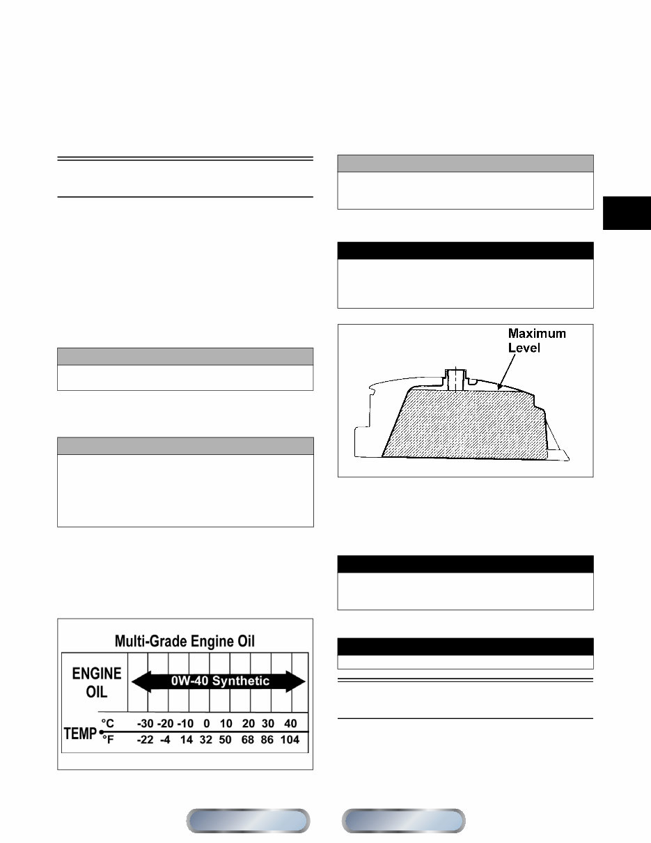
OILCHARTJ
RECOMMENDED FRONT
DIFFERENTIAL/REAR DRIVE
LUBRICANT
The recommended lubricant is Arctic Cat Gear Lube or
an equivalent gear lube which is SAE approved 80W-90
hypoid. This lubricant meets all of the lubrication
requirements of the Arctic Cat vehicle front differential
and rear drive.
FILLING GAS TANK
ATV0049B
Since gasoline expands as its temperature rises, the gas
tank must be filled to its specified capacity only. Expan-
sion room must be maintained in the tank particularly if
the tank is filled with cold gasoline and then moved to a
warm area.
Tighten the gas tank cap securely after filling the tank.
Genuine Parts
When replacement of parts is necessary, use only genuine
Arctic Cat parts. They are precision-made to ensure high
quality and correct fit. Refer to the appropriate Illustrated
Parts Manual for the correct part number, quantity, and
description.
CAUTION
Do not use white gas. Only Arctic Cat approved gaso-
line additives should be used.
CAUTION
Any oil used in place of the recommended oil could
cause serious engine damage. Do not use oils which
contain graphite or molybdenum additives. These oils
can adversely affect clutch operation. Also, not recom-
mended are racing, vegetable, non-detergent, and cas-
tor-based oils.
CAUTION
Any lubricant used in place of the recommended lubri-
cant could cause serious front differential/rear drive
damage.
! WARNING
Always fill the gas tank in a well-ventilated area. Never
add fuel to the gas tank near any open flames or with
the engine running. DO NOT SMOKE while filling the
gas tank.
! WARNING
Do not overflow gasoline when filling the gas tank. A
fire hazard could materialize. Always allow the engine to
cool before filling the gas tank.
! WARNING
Do not over-fill the gas tank.
Section
Table of Contents
Manual
Table of Contents

1-6
Preparation For Storage
1. Clean the seat cushion (cover and base) with a damp
cloth and allow it to dry.
2. Clean the vehicle thoroughly by washing dirt, oil,
grass, and other foreign matter from the entire vehi-
cle. Allow it to dry thoroughly. DO NOT get water
into any part of the engine or air intake.
3. Either drain the gas tank or add Fuel Stabilizer to the
gas in the gas tank. Remove the air filter housing
cover and air filter. Start the engine and allow it to
idle. Using Arctic Cat Engine Storage Preserver, rap-
idly inject the preserver into the air filter opening for
a period of 10 to 20 seconds; then stop the engine.
Install the air filter and housing cover.
4. Plug the exhaust hole in the exhaust system with a
clean cloth.
5. Apply light oil to the plungers of the shock absorb-
ers.
6. Tighten all nuts, bolts, cap screws, and screws. Make
sure rivets holding components together are tight.
Replace all loose rivets. Care must be taken that all
calibrated nuts, cap screws, and bolts are tightened to
specifications.
7. Fill the cooling system to the bottom of the stand
pipe in the radiator neck with properly mixed cool-
ant.
8. Disconnect the battery cables; then remove the bat-
tery, clean the battery posts and cables, and store in a
clean, dry area.
9. Store the vehicle indoors in a level position.
Preparation After
Storage
Taking the vehicle out of storage and correctly preparing
it will assure many miles and hours of trouble-free riding.
1. Clean the vehicle thoroughly.
2. Clean the engine. Remove the cloth from the exhaust
system.
3. Check all control wires and cables for signs of wear
or fraying. Replace if necessary.
4. Change the engine/transmission oil and filter.
5. Check the coolant level and add properly mixed
coolant as necessary.
6. Charge the battery; then install. Connect the battery
cables.
7. Check the entire brake systems (fluid level, pads,
etc.), all controls, headlights, taillight, brakelight,
and headlight aim; adjust or replace as necessary.
8. Tighten all nuts, bolts, cap screws, and screws mak-
ing sure all calibrated nuts, cap screws, and bolts are
tightened to specifications.
9. Check tire pressure. Inflate to recommended pres-
sure as necessary.
10. Make sure the steering moves freely and does not
bind.
11. Check the spark plug(s). Clean or replace as neces-
sary.
CAUTION
Prior to storing the vehicle, it must be properly serviced
to prevent rusting and component deterioration.
CAUTION
If the interior of the air filter housing is dirty, clean the
area before starting the engine.
CAUTION
Avoid storing outside in direct sunlight and avoid using
a plastic cover as moisture will collect on the vehicle
causing rusting.
CAUTION
The ignition switch must be in the OFF position prior to
installing the battery or damage may occur to the igni-
tion system.
CAUTION
Connect the positive battery cable first; then the nega-
tive.
Section
Table of Contents
Manual
Table of Contents

2-1
2
SECTION 2 -
PERIODIC MAINTENANCE/TUNE-UP
TABLE OF
CONTENTS
Periodic Maintenance Chart .................................... 2-2
Periodic Maintenance .............................................. 2-3
Lubrication Points .................................................... 2-3
Air Filter ................................................................... 2-3
Valve/Tappet Clearance (H1)................................... 2-4
Valve/Tappet Clearance (H2)................................... 2-4
Testing Engine Compression................................... 2-5
Spark Plug(s) .......................................................... 2-6
Muffler/Spark Arrester ............................................. 2-6
Engine/Transmission Oil - Filter............................... 2-7
Front Differential - Rear Drive Lubricant .................. 2-8
Driveshaft/Coupling ................................................. 2-8
Nuts/Bolts/Cap Screws............................................ 2-9
Headlight/Taillight-Brakelight ................................... 2-9
Shift Lever ............................................................... 2-9
Hydraulic Brake System ........................................ 2-10
Parking Brake ........................................................ 2-12
Burnishing Brake Pads .......................................... 2-14
Checking/Replacing V-Belt .................................... 2-14
Troubleshooting Brake System.............................. 2-16
Manual
Table of Contents

2-2
Periodic Maintenance
Chart
A = Adjust I = Inspect
C = Clean L = Lubricate
R = Replace T = Tighten
* Service/Inspect more frequently when operating in adverse conditions.
** When using an API certified SM 0W-40 oil.
*** When using Arctic Cat ACX All Weather synthetic oil, oil change and strainer inspection interval can be increased to every
1,000 miles or every year.
Item
Initial Service
After Break-In
(First Month or
100 Miles)
Every
Day
Every Month
or
Every 100
Miles
Every 3
Months or
Every 300
Miles
Every 6
Months or
Every 500
Miles
Every Year
or Every
1500 Miles
As
Needed
Battery I I C
Fuses I R
Air Filter I I* R
Valve/Tappet Clearance I I A
Engine Compression I
Spark Plug(s) I I I R (4000 Mi
or 18 Mo)
Muffler/Spark Arrester C R
Gas Hoses I I R (2 Yrs)
Throttle Cable Ends/Accelerator Pedal
Pivot
I I C-L A-R
Engine-Transmission Oil Level I A
Engine-Transmission Oil/Filter R R*/R**/R*** R
Front Differential - Rear Drive Lubricant I I R (4 Yrs)
Tires/Air Pressure I I R
Steering Components I I I R
V-Belt I l R
Suspension (Ball joint boots, drive axle
boots front and rear, tie rods, differential
and rear drive bellows)
I I R
Nuts/Bolts/Cap Screws T T A
Ignition Timing I
Headlight/Taillight-Brakelight I I R
Switches I I R
Shift Lever I A-L
Gauges/Indicators I I R
Frame/Welds I I l
Electrical Connections l C
Complete Brake System
(Hydraulic & Parking)
I I
Brake Pads I I* R
Brake Fluid I I R (2 Yrs)
Brake Hoses I I R (4 Yrs)
Coolant/Cooling System I I R (2 Yrs)
Wheel Lug Nuts T T
Section
Table of Contents
Manual
Table of Contents
2-3
2
Periodic Maintenance
This section has been organized into sub-sections which show
common maintenance procedures for the Arctic Cat ROV.
NOTE: Arctic Cat recommends the use of new gas-
kets, lock nuts, and seals and lubricating all internal
components when servicing the engine/transmission.
NOTE: Some photographs and illustrations used in
this section are used for clarity purposes only and
are not designed to depict actual conditions.
NOTE: Critical torque specifications are located in
Section 1.
SPECIAL TOOLS
A number of special tools must be available to the techni-
cian when performing service procedures in this section.
Refer to the current Special Tools Catalog for the appro-
priate tool description.
NOTE: Special tools are available from the Arctic
Cat Service Department.
Lubrication Points
It is advisable to lubricate certain components periodi-
cally to ensure free movement. Apply light oil to the
components using the following list as reference.
A. Accelerator Pedal Pivot/Cable Ends
B. Brake Pedal Pivot
C. Parking Brake Cable Ends
D. Shift Cable
Air Filter
Use the following procedure to remove the filter and
inspect and/or clean it.
CLEANING AND INSPECTING
FILTER
1. Remove the seats; then remove the center console.
2. Unsnap the four fasteners securing the air cleaner
housing cover and remove the cover.
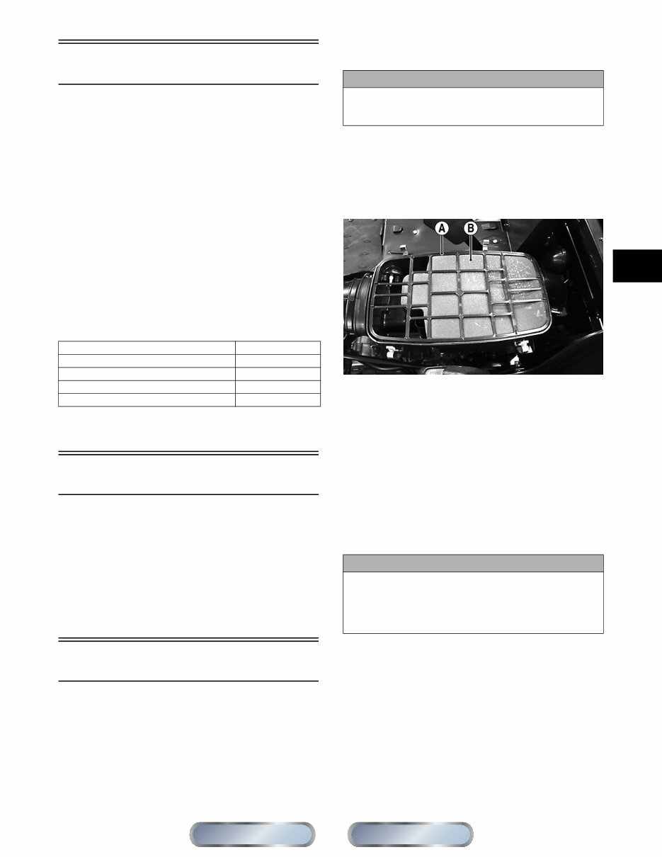
3. Remove the air filter frame (A); then remove the
foam filter element (B).
PR576A
4. Fill a wash pan larger than the filter with a non-flam-
mable cleaning solvent; then dip the filter in the sol-
vent and wash it.
NOTE: Foam Filter Cleaner and Foam Filter Oil are
available from Arctic Cat.
5. Dry the filter.
6. Put the filter in a plastic bag; then pour in air filter oil
and work the filter. Reattach the filter to the filter screen.
NOTE: Carefully squeeze excessive oil from the fil-
ter element. Do not twist foam to remove oil.
7. Clean any dirt or debris from inside the air cleaner.
Be sure no dirt enters the throttle body.
8. Place the foam filter in the air filter housing; then
position the filter frame on top.
9. Install the air filter housing cover and secure with the
retaining clips; then install the center console and
seats making sure the seats lock securely.
CHECKING AND CLEANING
DRAINS
1. Inspect one-way drains beneath the main housing for
debris and for proper sealing.
Description p/n
Compression Tester Kit 0444-213
Oil Filter Wrench 0644-389
Timing Light 0644-296
Valve Clearance Adjuster 0444-255
CAUTION
Failure to inspect the air filter frequently if the vehicle is
used in dusty, wet, or muddy conditions can damage
the engine.
CAUTION
A torn air filter can cause damage to the vehicle engine.
Dirt and dust may get inside the engine if the element is
torn. Carefully examine the element for tears before and
after cleaning it. Replace the element with a new one if it
is torn.
Section
Table of Contents
Manual
Table of Contents
You're Reading a Preview
What's Included?
Fast Download Speeds
Online & Offline Access
Access PDF Contents & Bookmarks
Full Search Facility
Print one or all pages of your manual
$31.99
Viewed 17 Times Today


Secure transaction
What's Included?
Fast Download Speeds
Online & Offline Access
Access PDF Contents & Bookmarks
Full Search Facility
Print one or all pages of your manual
$31.99
Get instant access to the service/repair information for the 2012 Arctic Cat Prowler HDX models with this manual. It provides all the technical information you need, including work procedures, part numbers, torque specs, and exploded views for performing service/maintenance and repairs on your vehicle. Whether you're a professional mechanic or a DIY enthusiast, this manual is easy to use and can be viewed and printed on your desktop computer, laptop, or tablet.


