TABLE OF CONTENTS Click on the Red text to go. Forward Section 1. General Information 2. Periodic Maintenance/Tune-Up 3. Engine/Transmission 4. Fuel/Lubrication/Cooling 5. Electrical System 6. Drive System 7. Suspension 8. Steering/Frame 9. Controls/Indicators 10. Aids for Maintenance 11. Troubleshooting 1 2 3 4 5 6 7 8 9 10 11 MORE TO GO ON. TM
1-1 1 SECTION 1 - GENERAL INFORMATION TABLE OF CONTENTS General Specifications ............................................ 1-2 Break-In Procedure ................................................. 1-3 Gasoline - Oil - Lubricant ........................................ 1-3 Genuine Parts ......................................................... 1-4 Preparation For Storage .......................................... 1-4 Preparation After Storage........................................ 1-5 Back to TOC
1-2 General Specifications* * Specifications subject to change without notice. ** At the oil level plug threads. *** At the filler plug threads. CARBURETOR Type Keihin CVK36 Main Jet 132 Slow Jet 40 Low Speed Fuel Screw Setting (turns) 1 1/4 Jet Needle NFKS Needle Jet 6.0/4.0 Idle RPM 1250-1350 Starter Jet 85 Float Arm Height 17 mm (0.7 in.) Throttle Cable Free-Play (at lever) 3-6 mm (1/8-1/4 in.) ELECTRICAL Ignition Timing 10° BTDC @ 1500 RPM Spark Plug Type Champion R6YCA Spark Plug Gap 0.7-0.8 mm (0.028-0.032 in.) Spark Plug Cap 4000-6000 ohms Ignition Coil Resistance (primary) (secondary) Less than 1 ohm (terminal to ground) 5200-7800 ohms (high tension - plug cap removed - to ground) Ignition Coil Peak Voltage (static) (primary/CDI) 132-198 DC volts (terminal to ground) Magneto Coil Resistance (trigger) (source) (charging) 160-240 ohms (green to blue) Less than 1 ohm (yellow to white) Less than 1 ohm (black to black) Magneto Coil Peak Voltage (trigger) (source) 4.2-6.3 volts (green to blue) 0.40-0.62 volt (yellow to white) Stator Coil Output (no load) 60 AC volts @ 5000 RPM (black to black #1) (black to black #2) Magneto Output (approx) 325W @ 5000 RPM CHASSIS Dry Weight (approx) 533 kg (1175 lb) Length (overall) 292 cm (115 in.) Height (overall) 197 cm (77.5 in.) Width (overall) 156 cm (61.3 in.) Suspension Travel (front) 25 cm (10 in.) Suspension Travel (rear) 20 cm (8 in.) Brake Type Hydraulic Wheelbase 190 cm (75 in.) Tracking (front) (rear) 128.3 cm (50.5 in.) 123.2 cm (48.5 in.) Tire Size (front) (rear) 26 x 9-14 26 x 11-14 Tire Inflation Pressure 0.70 kg/cm² (10 psi) Turning Radius 3.3 m (10.8 ft) MISCELLANY Gas Tank Capacity (rated) 31 L (8.2 U.S. gal.) Coolant Capacity 2.9 L (3.0 U.S. qt) Differential Capacity 275 ml (9.3 fl oz)** Rear Drive Capacity 250 ml (8.5 fl oz)*** Engine Oil Capacity 2.5 L (2.6 U.S. qt) Gasoline (recommended) 87 Octane Regular Unleaded Engine Oil (recommended) SAE 10W-40 Differential/Rear Drive Lubricant SAE Approved 80W-90 Hypoid Belt Width 35.0 mm (1.38 in.) Brake Fluid DOT 4 Taillight/Brakelight 12V/8W/27W Headlight 12V/27W (2) Starting System Electric Back to TOC Back to Section TOC Next
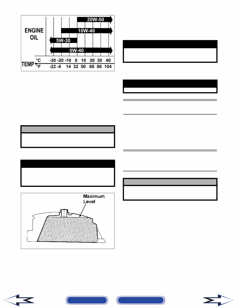
1-3 1 Break-In Procedure A new vehicle and an overhauled engine require a “break-in” period. The first 10 hours (or 200 miles) are most critical to the life of this vehicle. Proper operation during this break-in period will help assure maximum life and performance from the vehicle. During the first 10 hours (or 200 miles) of operation, always use less than 1/2 throttle. Varying the engine RPM during the break-in period allows the compo- nents to “load” (aiding the mating process) and then “unload” (allowing components to cool). Although it is essential to place some stress on the engine components during break-in, care should be taken not to overload the engine too often. Do not pull a trailer or carry heavy loads during the 10-hour break-in period. When the engine starts, allow it to warm up prop- erly. Idle the engine several minutes until the engine has reached normal operating temperature. Do not idle the engine for excessively long periods of time. During the break-in period, a maximum of 1/2 throt- tle is recommended; however, brief full-throttle accelerations and variations in driving speeds con- tribute to good engine break-in. During the break-in period (or whenever the brake pads are replaced), the hydraulic brake pads must be burnished. Slow disc-speed hydraulic brakes must be properly burnished in order to achieve maximum stopping power. NOTE: Do not be reluctant to heat up the brake pads during the burnishing procedure. After the completion of the break-in period, the engine oil and oil filter should be changed. Other maintenance after break-in should include checking of all prescribed adjustments and tightening of all fasteners. Gasoline - Oil - Lubricant RECOMMENDED GASOLINE The recommended gasoline to use is 87 minimum octane regular unleaded. In many areas, oxygenates (either ethanol or MTBE) are added to the gasoline. Oxygenated gasolines containing up to 10% ethanol, 5% methane, or 5% MTBE are acceptable gasolines. When using ethanol blended gasoline, it is not nec- essary to add a gasoline antifreeze since ethanol will prevent the accumulation of moisture in the fuel sys- tem. RECOMMENDED ENGINE/ TRANSMISSION OIL The recommended oil to use is Arctic Cat 4-Cycle Engine Oil (p/n 0436-005) or an equivalent oil which is rated SE, SF, or SG under API service clas- sification. These oils meet all of the lubrication requirements of the Arctic Cat engine. The recom- mended engine oil viscosity is SAE 10W-40. Ambi- ent temperature should determine the correct weight of oil. See the following viscosity chart for details. ! CAUTION BRAKE PADS MUST BE BURNISHED TO ACHIEVE FULL BRAKING EFFECTIVENESS. Braking dis- tance will be extended until brake pads are properly burnished. TO PROPERLY BURNISH THE BRAKES, USE FOL- LOWING PROCEDURE: • Choose an area sufficiently large to safely accel- erate vehicle to 30 mph and to brake to a stop. • Accelerate to 30 mph; then compress brake lever to decelerate to 0-5 mph. • Repeat procedure five times until brakes are bur- nished. • This procedure burnishes the brake pads, stabi- lizes the pad material, and extends the life of the brake pads. ! WARNING Do not attempt sudden stops or put the vehicle into a situation where a sudden stop will be required until the brake pads are properly burnished. ! CAUTION Do not use white gas. Only Arctic Cat approved gasoline additives should be used. ! CAUTION Any oil used in place of the recommended oil could cause serious engine damage. Do not use oils which contain graphite or molybdenum additives. These oils can adversely affect clutch operation. Also, not recommended are racing, vegetable, non- detergent, and castor-based oils. Back to TOC Back to Section TOC Next Back
1-4 OILCHARTB RECOMMENDED FRONT DIFFERENTIAL/REAR DRIVE LUBRICANT The recommended lubricant is Arctic Cat Gear Lube (p/n 0436-007) or an equivalent gear lube which is SAE approved 80W-90 hypoid. This lubricant meets all of the lubrication requirements of the Arctic Cat vehicle front differentials and rear drives. FILLING GAS TANK ATV0049B Since gasoline expands as its temperature rises, the gas tank must be filled to its rated capacity only. Expansion room must be maintained in the tank par- ticularly if the tank is filled with cold gasoline and then moved to a warm area. Tighten the gas tank cap securely after filling the tank. Genuine Parts When replacement of parts is necessary, use only genuine Arctic Cat parts. They are precision-made to ensure high quality and correct fit. Refer to the Illustrated Parts Manual for the correct part number, quantity, and description. Preparation For Storage Arctic Cat recommends the following procedure to prepare the vehicle for storage. 1. Clean the seat cushion (cover and base) with a damp cloth and allow it to dry. 2. Clean the vehicle thoroughly by washing dirt, oil, grass, and other foreign matter from the entire vehicle. Allow it to dry thoroughly. DO NOT get water into any part of the engine or air intake. ! CAUTION Any lubricant used in place of the recommended lubricant could cause serious front differential/rear drive damage. ! WARNING Always fill the gas tank in a well-ventilated area. Never add fuel to the gas tank near any open flames or with the engine running. DO NOT SMOKE while filling the gas tank. ! WARNING Do not overflow gasoline when filling the gas tank. A fire hazard could materialize. Always allow the engine to cool before filling the gas tank. ! WARNING Do not over-fill the gas tank. ! CAUTION Prior to storing the vehicle, it must be properly ser- viced to prevent rusting and component deteriora- tion. Back to TOC Back to Section TOC Next Back
1-5 1 3. Either drain the gas tank or add Fuel Stabilizer (p/n 0638-165) to the gas in the gas tank. Remove the air filter housing cover and air fil- ter. Start the engine and allow it to idle; then using Arctic Cat Engine Storage Preserver (p/n 0636-177), rapidly inject the preserver into the air filter opening for a period of 10 to 20 sec- onds; then stop the engine. Install the air filter and housing cover. 4. Drain the carburetor float chamber. 5. Plug the exhaust hole in the exhaust system with a clean cloth. 6. Apply light oil to the plungers of the shock absorbers. 7. Tighten all nuts, bolts, cap screws, and screws. Make sure rivets holding components together are tight. Replace all loose rivets. Care must be taken that all calibrated nuts, cap screws, and bolts are tightened to specifications. 8. Fill the cooling system to the bottom of the stand pipe in the radiator neck with properly mixed coolant. 9. Disconnect the battery cables; then remove the battery, clean the battery posts and cables, and store in a clean, dry area. 10. Store the vehicle indoors in a level position. Preparation After Storage Taking the vehicle out of storage and correctly pre- paring it will assure many miles and hours of trou- ble-free riding. Arctic Cat recommends the following procedure to prepare the vehicle. 1. Clean the vehicle thoroughly. 2. Clean the engine. Remove the cloth from the exhaust system. 3. Check all control wires and cables for signs of wear or fraying. Replace if necessary. 4. Change the engine/transmission oil and filter. 5. Check the coolant level and add properly mixed coolant as necessary. 6. Charge the battery; then install. Connect the bat- tery cables. 7. Check the entire brake systems (fluid level, pads, etc.), all controls, headlights, taillight, brakelight, and headlight aim; adjust or replace as necessary. 8. Tighten all nuts, bolts, cap screws, and screws making sure all calibrated nuts, cap screws, and bolts are tightened to specifications. 9. Check tire pressure. Inflate to recommended pressure as necessary. 10. Make sure the steering moves freely and does not bind. 11. Check the spark plug. Clean or replace as neces- sary. 12. Follow the recommendations found in the pre- start inspection. ! CAUTION If the interior of the air filter housing is dirty, clean the area before starting the engine. ! CAUTION Avoid storing outside in direct sunlight and avoid using a plastic cover as moisture will collect on the vehicle causing rusting. ! CAUTION The ignition switch must be in the OFF position prior to installing the battery or damage may occur to the ignition system. ! CAUTION Connect the positive battery cable first; then the negative. Back to TOC Back to Section TOC Back
2-2 Periodic Maintenance Chart A = Adjust I = Inspect C = Clean L = Lubricate D = Drain R = Replace * Service/Inspect more frequently when operating in adverse conditions. Item Initial Service After Break-In (First Mo or 100 Mi) Every Day Every Month or Every 100 Miles Every 3 Months or Every 300 Miles Every 6 Months or Every 500 Miles Every Year or Every 1500 Miles As Needed Battery I I C Fuses I R Air Filter/Drain Tube I I C* R Valve/Tappet Clearance I I A Engine Compression I Spark Plug I I R (4000 Mi or 18 Mo) Muffler/Spark Arrester C R Gas/Vent Hoses I I R (2 Yrs) Throttle Cable I I C-L A-R Carb Float Chamber D* Engine RPM (Idle) I I A Engine-Transmission Oil Level I A Engine-Transmission Oil/Filter R R* R Oil Strainer I I C Front Differential/Rear Drive Lubricant I R (4 Yrs) Tires/Air Pressure I I R Steering Components I I I R V-Belt (Automatic) I l R Suspension (Ball joint boots, drive axle boots front and rear, tie rods, differen- tial and rear drive bellows) I I R Nuts/Cap Screws/Screws I I I A Ignition Timing I Headlight/Taillight- Brakelight I I R Switches I I R Shift Lever I A-L Gauges/Indicators I I R Frame/Welds I I l Electrical Connections l C Complete Brake System (Hydraulic & Parking) I I C L-R Brake Pads I I* R Brake Fluid I I R (2 Yrs) Brake Hoses I I R (4 Yrs) Coolant/Cooling System I I R (2 Yrs) Back to TOC Back to Section TOC Next
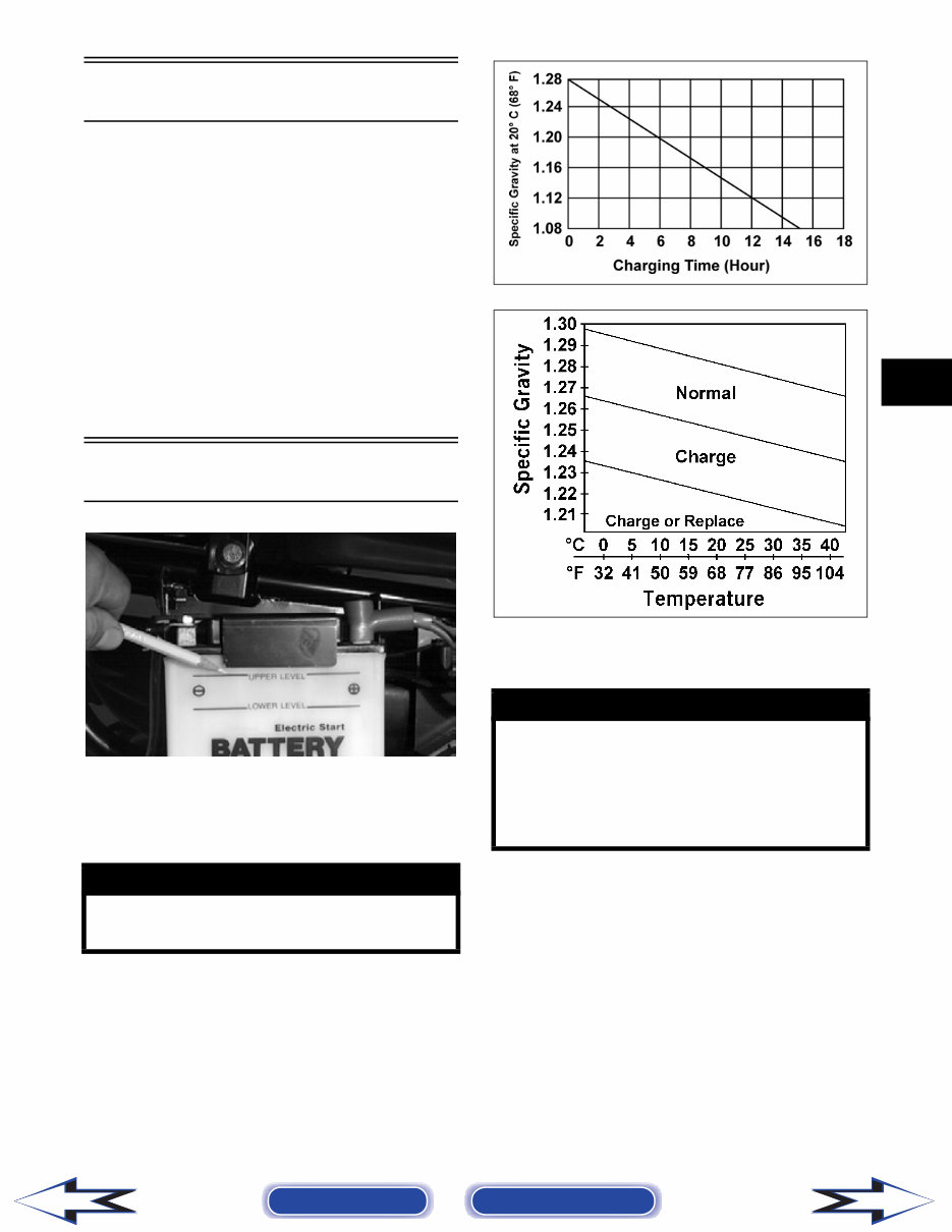
2-3 2 Lubrication Points It is advisable to lubricate certain components peri- odically to ensure free movement. Apply light oil to the components using the following list as reference. A. Accelerator Pedal Pivot/Cable Ends B. Brake Pedal Pivot C. Parking Brake Cable Ends D. Shift Linkage E. Differential Lock Cable End F. Idle RPM Screw (Carburetor) Battery AF879D The level of the battery fluid must be kept between the upper and lower level lines at all times. If the level drops below the lower level line, add only dis- tilled water until it reaches upper level line. If the battery is discharged, remove the battery from the vehicle and charge the battery at the standard charging rate of 1.5A x 10 hr. CHARGTIM CHARGE To remove and charge the battery, use the following procedure. 1. Remove the fasteners holding the left-rear splash panel in place; then remove the battery access panel. ! WARNING Battery acid is harmful if it contacts eyes, skin, or clothing. Care must be taken whenever handling a battery. ! WARNING Anytime service is performed on a battery, the fol- lowing must be observed: keep sparks, open flame, cigarettes, or any other flame away. Always wear safety glasses. Protect skin and clothing when han- dling a battery. When servicing battery in enclosed space, keep the area well-ventilated. Make sure bat- tery venting is not obstructed. Back to TOC Back to Section TOC Next Back
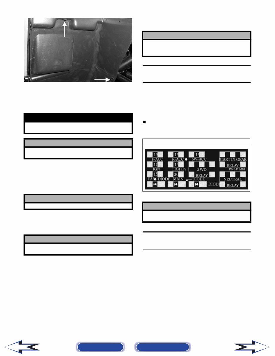
2-4 PR054A 2. Remove the negative battery cable; then remove the positive cable and the battery vent tube. Remove the battery from the vehicle. Care should be taken not to damage the vent tube. 3. Remove the vent plugs; then (if necessary) fill the battery with distilled water to the upper level indicated on the battery. 4. Trickle charge the battery at 1.5A for 10 hours. 5. After charging, check fluid level and fill with distilled water as necessary; then install vent plugs. 6. Attach the vent tube and check the vent tube to make sure it is not crimped or obstructed in any way and that it is properly routed through and secured to the frame. 7. Connect cables to the proper terminals: positive cable to the positive terminal (+) and negative cable to the negative terminal (-). Connect the negative cable last. 8. Place the battery into position in the vehicle and secure with the battery access panel. Fuses The main fuses are located in a power distribution module under the operator’s seat. If there is any type of electrical system failure, always check the fuses first. NOTE: To remove the fuse, compress the locking tabs on either side of the fuse case and lift out. 1411-191 Air Cleaner/Filter The air filter inside the air filter housing must be kept clean to provide good engine power and gas mileage. If the vehicle is used under normal condi- tions, service the filter at the intervals specified. If operated in dusty, wet, or muddy conditions, inspect and service the filter more frequently. Use the fol- lowing procedure to remove the filter and inspect and/or clean it. ! WARNING Avoid spillage and contact with skin, eyes, and clothing. ! CAUTION Do not charge the battery while it is in the vehicle with the battery terminals connected. ! CAUTION Never exceed the standard charging rate. ! CAUTION Before installing the battery, make sure the ignition switch is in the OFF position. ! CAUTION Connecting cables in reverse (positive to negative and negative to positive) can cause serious dam- age to the electrical system. Prowler XT ! CAUTION Always replace a blown fuse with a fuse of the same type and rating. Back to TOC Back to Section TOC Next Back
MyGreenManuals.com is your number one source for repair manuals. Our informative repair manual, owner's manuals, and parts catalogs contain all the information you'll need to perform repairs, look up parts, or do routine maintenance on your machine. You will have access to information regarding the following topics:
General Information
Routine Maintenance
Engine Removal and Installation
Fuel System
Lubrication and Cooling System
Engine Specifications
Transmission, Drive Chain & Sprockets
Steering System
Shocks
Body Work
Intake & Exhaust
Electrical System
Advanced Troubleshooting
And much more! With our repair manuals, find the page pertaining to your job, print it off, and get working on your machine. No more ruining your expensive paper shop manual with grease and dirt.
Broke down on the trail or site and have a smartphone? What a cool way to find your problem and repair it on the trail, no downtime on the job site. With our repair manuals, you instantly have access to the material needed to get you running again. Kind of tough to do that with a paper manual.
And did we mention the fact that you're saving the trees? All our repair manuals come with a lifetime protection policy. If lost or damaged, simply contact us, and we'll replace it free of charge for life.
We provide various repair service manuals, workshop manuals, repair manuals, owner's manuals, parts catalogs, and other various manuals, all in an electronic format.
UTVs, motorcycles, ATVs, quads, snowmobiles, Seadoo, equipment, small engines, inboards, outboards, and more.
Instant Access
No Shipping Cost
Get a Download So No Waiting, Repair It Now
If you are looking for a specific manual and cannot find it or do not see it listed, then contact our customer support team via the contact us link above with details of the required manual, and we will do our absolute best to find and list it for you. Instant access after payment. Thank you.