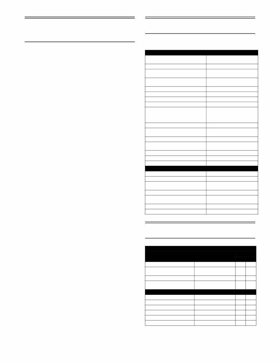
2 General Information/Foreword This Arctic Cat Service Manual contains service, mainte- nance, and troubleshooting information for certain 2016 Arctic Cat Alterra ATV models (see cover). The com- plete manual is designed to aid service personnel in ser- vice-oriented applications. This manual is divided into sections. Each section covers a specific ATV component or system and, in addition to the standard service procedures, includes disassembling, inspecting, and assembling instructions. When using this manual as a guide, the technician should use discretion as to how much disassembly is needed to correct any given condition. This service manual is designed primarily for use by an Arctic Cat CatMaster Basic Level technician. The proce- dures found in this manual are of varying difficulty, and certain service procedures in this manual require one or more special tools to be completed. The technician should use sound judgement when determining which procedures can be completed based on skill level and access to appropriate special tools. NOTE: Whenever a part is worn excessively, cracked, or damaged in any way, replacement is nec- essary. When replacement of parts is necessary, use only genuine Arctic Cat ATV parts. They are precision-made to ensure high quality and correct fit. Refer to the appropriate Illus- trated Parts Manual for the correct part number, quantity, and description. All Arctic Cat ATV publications and decals display the words Warning, Caution, Note, and At This Point to emphasize important information. The symbol ! WARNING identifies personal safety-related infor- mation. Be sure to follow the directive because it deals with the possibility of severe personal injury or even death. A CAUTION identifies unsafe practices which may result in ATV-related damage. Follow the directive because it deals with the possibility of damaging part or parts of the ATV. The symbol NOTE: identifies sup- plementary information worthy of particular attention. The symbol AT THIS POINT directs the tech- nician to certain and specific procedures to promote effi- ciency and to improve clarity. At the time of publication, all information, photographs, and illustrations were technically correct. Some photo- graphs used in this manual are used for clarity purposes only and are not designed to depict actual conditions. Because Arctic Cat Inc. constantly refines and improves its products, no retroactive obligation is incurred. All materials and specifications are subject to change without notice. Product Service and Warranty Department Arctic Cat Inc. Specifications NOTE: Specifications subject to change without notice. * One inch below plug threads. ** At the plug threads. Torque Specifications MISCELLANY Tire Size Front - 25 x 8-12 Rear - 25 x 10-12 Tire Inflation Pressure 0.35 kg/cm² (5 psi) Spark Plug Type (500) (550/700) NGK CR7E NGK CPR8E Spark Plug Gap (500) (550/700) 0.7-0.8 mm (0.028-0.031 in.) 0.5-0.6 mm (0.019-0.024 in.) Gas Tank Capacity 21.6 L (5.7 U.S. gal.) Coolant Capacity 2.9 L (3.0 U.S. qt) Rear Drive Capacity 250 ml (8.5 fl oz)* Front Differential Capacity 275 ml (9.3 fl oz)** Engine Oil Capacity (approx) (500) (550/700) 2.8 L (3.0 U.S. qt) - Overhaul 2.5 L (2.6 U.S. qt) - Change 2.5 L (2.6 U.S. qt) - Overhaul 1.9 L (2.0 U.S. qt) - Change Gasoline (recommended) 87 Octane Regular Unleaded Engine Oil (recommended) Arctic Cat ACX All Weather (Synthetic) Differential/Rear Drive Lubricant SAE Approved 80W-90 Hypoid Drive Belt Width 28.5 mm (1.12 in.) - 500 35.0 mm (1.28 in.) - 550/700 Brake Fluid DOT 4 Taillight/Brakelight High Intensity LED Headlight High Intensity LED ELECTRICAL SYSTEM Ignition Timing 10° BTDC @ 1500 RPM Spark Plug Cap 5000 ohms Ignition Coil Resistance (primary) (secondary) Less than 5.0 ohms N.A. Ignition Coil Primary Voltage Battery Voltage Stator Coil (CKP sensor) Resistance (AC generator) 104-156 ohms Less than 1 ohm Crankshaft Position Sensor 2.0 AC volts or more AC Generator Output (no load) 75 AC volts @ 5000 RPM EXHAUST COMPONENTS Part Part Bolted To Torque ft-lb N-m Exhaust Pipe Engine 20 27 Spark Arrester Muffler 48 in.-lb 5.5 Heat Shield Exhaust Pipe 8 11 Heat Shield Frame 54 in.-lb 6 STEERING COMPONENTS Steering Shaft Frame 20 27 Steering Shaft Flange Frame 11 15 Steering Post Handlebar Block 20 27 Tie Rod End** Knuckle/Steering Shaft 55 74 EPS Housing Frame 35 47 Handlebar End Cap Handlebar 8 11
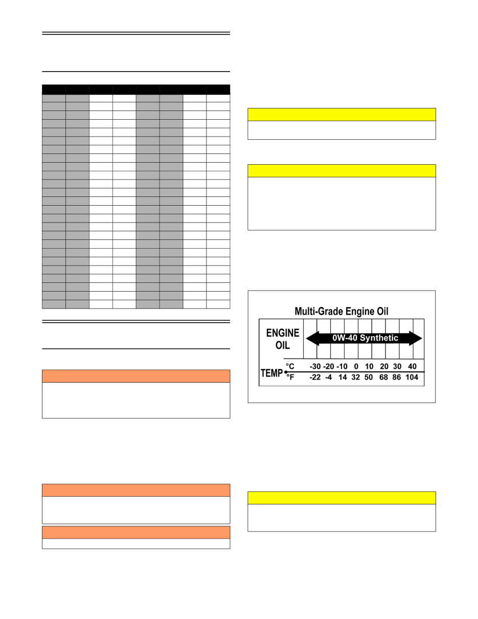
4 Torque Conversions (ft-lb/N-m) Gasoline - Oil - Lubricant FILLING GAS TANK Since gasoline expands as its temperature rises, the gas tank must be filled to its rated capacity only. Expansion room must be maintained in the tank particularly if the tank is filled with cold gasoline and then moved to a warm area. Tighten the gas tank cap securely after filling the tank. RECOMMENDED GASOLINE The recommended gasoline to use is 87 minimum octane regular unleaded. In many areas, oxygenates are added to the gasoline. Oxygenated gasolines containing up to 10% ethanol or 5% methane are acceptable gasolines. When using ethanol blended gasoline, it is not necessary to add a gasoline antifreeze since ethanol will prevent the accumulation of moisture in the fuel system. RECOMMENDED ENGINE/ TRANSMISSION OIL The recommended oil to use is Arctic Cat ACX All Weather synthetic which has been specifically formu- lated for use in this Arctic Cat engine. Although Arctic Cat ACX All Weather synthetic engine oil is the only oil recommended for use in this engine, use of any API certi- fied SM 0W-40 oil is acceptable. OILCHARTJ RECOMMENDED FRONT DIFFERENTIAL/REAR DRIVE LUBRICANT The recommended lubricant is Arctic Cat Gear Lube or an equivalent gear lube which is SAE approved 80W-90 hypoid. This lubricant meets all of the lubrication requirements of the Arctic Cat ATV front differentials and rear drives. ft-lb N-m ft-lb N-m ft-lb N-m ft-lb N-m 1 1.4 26 35.4 51 69.4 76 103.4 2 2.7 27 36.7 52 70.7 77 104.7 3 4.1 28 38.1 53 72.1 78 106.1 4 5.4 29 39.4 54 73.4 79 107.4 5 6.8 30 40.8 55 74.8 80 108.8 6 8.2 31 42.2 56 76.2 81 110.2 7 9.5 32 43.5 57 77.5 82 111.5 8 10.9 33 44.9 58 78.9 83 112.9 9 12.2 34 46.2 59 80.2 84 114.2 10 13.6 35 47.6 60 81.6 85 115.6 11 15 36 49 61 83 86 117 12 16.3 37 50.3 62 84.3 87 118.3 13 17.7 38 51.7 63 85.7 88 119.7 14 19 39 53 64 87 89 121 15 20.4 40 54.4 65 88.4 90 122.4 16 21.8 41 55.8 66 89.8 91 123.8 17 23.1 42 57.1 67 91.1 92 125.1 18 24.5 43 58.5 68 92.5 93 126.5 19 25.8 44 59.8 69 93.8 94 127.8 20 27.2 45 61.2 70 95.2 95 129.2 21 28.6 46 62.6 71 96.6 96 130.6 22 29.9 47 63.9 72 97.9 97 131.9 23 31.3 48 65.3 73 99.3 98 133.3 24 32.6 49 66.6 74 100.6 99 134.6 25 34 50 68 75 102 100 136 ! WARNING Always fill the gas tank in a well-ventilated area. Never add gasoline to the ATV gas tank near any open flames or with the engine running. DO NOT SMOKE while filling the gas tank. ! WARNING Do not overflow gasoline when filling the gas tank. A fire hazard could materialize. Always allow the engine to cool before filling the gas tank. ! WARNING Do not over-fill the gas tank. CAUTION Do not use white gas. Only Arctic Cat approved gaso- line additives should be used. CAUTION Any oil used in place of the recommended oil could cause serious engine damage. Do not use oils which contain graphite or molybdenum additives. These oils can adversely affect clutch operation. Also, not recom- mended are racing, vegetable, non-detergent, and cas- tor-based oils. CAUTION Any lubricant used in place of the recommended lubri- cant could cause serious front differential/rear drive damage.
5 Preparation For Storage Arctic Cat recommends the following procedure to pre- pare the ATV for storage. An authorized Arctic Cat ATV dealer should perform this service; however, the owner/operator may perform this service if desired. 1. Clean the seat cushion (cover and base) with a damp cloth and allow to dry. 2. Clean the ATV thoroughly by washing dirt, oil, grass, and other foreign matter from the entire ATV. Allow the ATV to dry thoroughly. DO NOT get water into any part of the engine or air intake. 3. Either drain the gas tank or add a fuel stabilizer to the gas in the gas tank. 4. Clean the interior of the air filter housing. 5. Plug the hole in the exhaust system with a clean cloth. 6. Apply light oil to the upper steering post bushing and plungers of the shock absorbers. 7. Tighten all nuts, bolts, cap screws, and screws. Make sure rivets holding components together are tight. Replace all loose rivets. Care must be taken that all calibrated nuts, cap screws, and bolts are tightened to specifications. 8. Fill the cooling system to the bottom of the stand pipe in the radiator neck with properly mixed cool- ant. 9. Disconnect the battery cables (negative cable first); then remove the battery, clean the battery posts and cables, and store in a clean, dry area. NOTE: For storage, use a battery maintainer or make sure the battery is fully charged (see Battery section in this manual). 10. Store the ATV indoors in a level position. Preparation After Storage Taking the ATV out of storage and correctly preparing it will assure many miles and hours of trouble-free riding. Arctic Cat recommends the following procedure to pre- pare the ATV. 1. Clean the ATV thoroughly. 2. Clean the engine. Remove the cloth from the exhaust system. 3. Check all control wires and cables for signs of wear or fraying. Replace if necessary. 4. Change the engine/transmission oil and filter. 5. Check the coolant level and add properly mixed coolant as necessary. 6. Charge the battery; then install. Connect the battery cables making sure to connect the positive cable first. 7. Check the entire brake systems (fluid level, pads, etc.), all controls, headlights, taillight, brakelight, and headlight aim; adjust or replace if necessary. 8. Check the tire pressure. Inflate to recommended pressure as necessary. 9. Tighten all nuts, bolts, cap screws, and screws mak- ing sure all calibrated nuts, cap screws, and bolts are tightened to specifications. 10. Make sure the steering moves freely and does not bind. 11. Check the spark plug. Clean or replace as necessary. 12. Check the air filter and the air filter housing. Clean or replace as necessary. CAUTION Prior to storing the ATV, it must be properly serviced to prevent rusting and component deterioration. CAUTION Avoid storing outside in direct sunlight and avoid using a plastic cover as moisture will collect on the ATV caus- ing rusting. CAUTION Before installing the battery, make sure the ignition switch is in the OFF position.
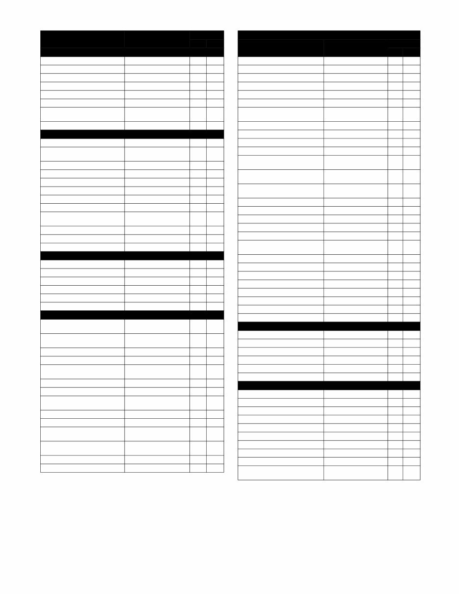
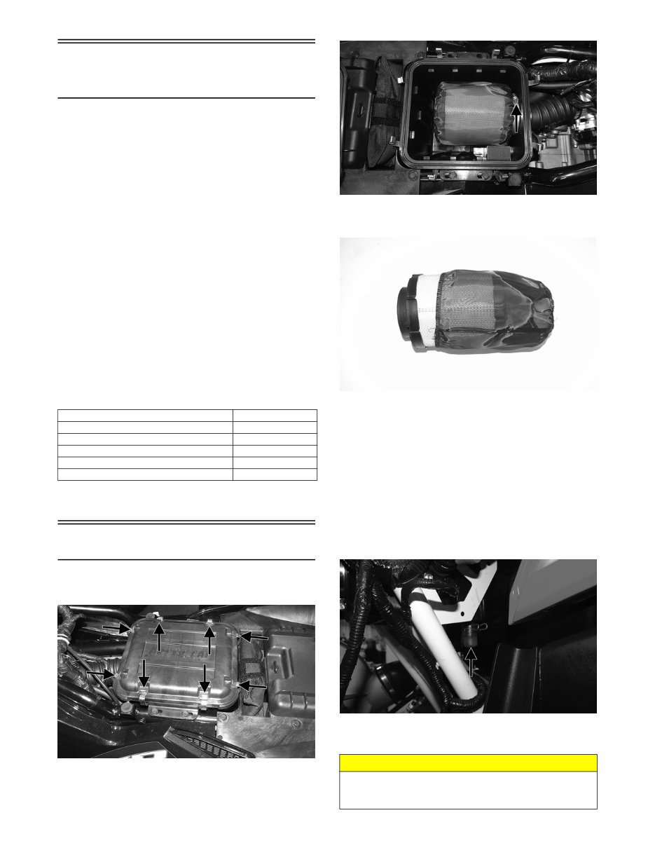
6 Periodic Maintenance/Tune-up Tighten all nuts, bolts, and cap screws. Make sure rivets holding components together are tight. Replace all loose rivets. Care must be taken that all calibrated nuts, bolts, and cap screws are tightened to specifications (see Gen- eral Information/Foreword). It is advisable to lubricate certain components periodi- cally to ensure free movement. Apply light oil to the components using the following list as reference. A. Throttle Lever Pivot B. Brake Lever Pivot C. Auxiliary Brake Pedal Pivot NOTE: Arctic Cat recommends the use of new gas- kets, lock nuts, and seals and lubricating all internal components when servicing the engine/transmission. SPECIAL TOOLS A number of special tools must be available to the techni- cian when performing service procedures in this section. NOTE: When indicated for use, each special tool will be identified by its specific name, as shown in the chart below, and capitalized. NOTE: Special tools are available from the Arctic Cat Service Department. Air Filter 1. Remove the seat; then remove the clips securing the air filter housing cover. XR002A 2. Loosen the clamp securing the air filter to the inside of the housing; then remove the filter. XR029A 3. Carefully remove the pre-filter from the air filter. If the air filter is dirty, it must be replaced. XR049 4. Using an air hose, clean the pre-filter. 5. Slide the pre-filter over the closed end of the new fil- ter and install into the housing. Tighten the clamp securely. 6. Install the air filter housing cover and secure with the clips. 7. Install the seat. CHECKING AND CLEANING DRAINS 1. Inspect the drains beneath the main housing for water/oil and for proper sealing. XR055A 2. Replace any drain that is cracked or shows any signs of hardening or deterioration. Description p/n Compression Tester Kit 0444-213 Drive Belt Gauge 0444-177 Oil Filter Wrench 0644-389 Spanner Wrench 0444-240 Valve Clearance Adjuster 0444-255 CAUTION The drain to the right is the clean air section of the filter housing. Any leak of this drain will allow dirt into the engine intake causing severe engine damage.
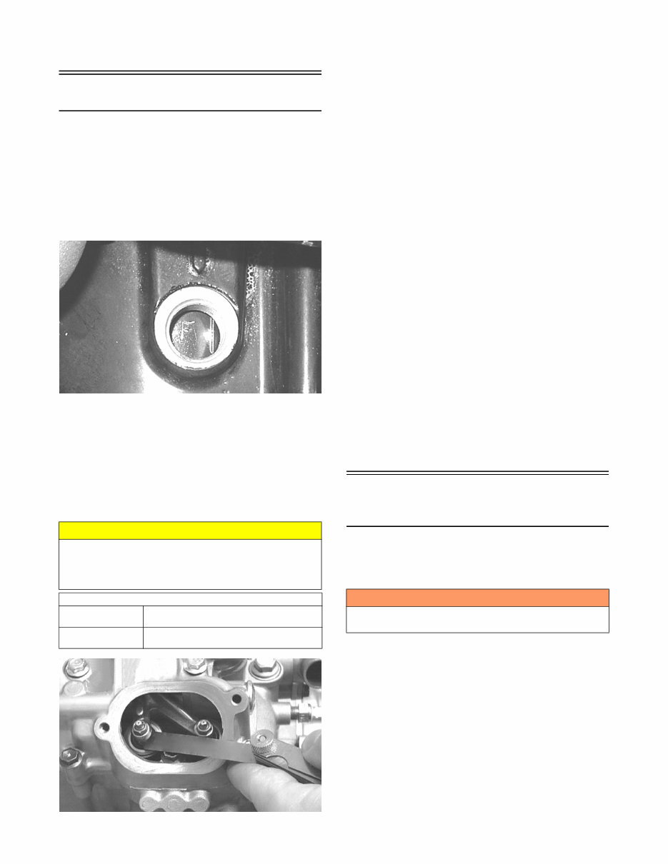
7 3. Wipe any accumulation of oil or gas from the filter housing and drains. Valve/Tappet Clearance To check and adjust valve/tappet clearance, use the fol- lowing procedure. 1. Remove the timing inspection plug; then remove the tappet covers and spark plug (for more detailed information, see Engine/Transmission - Servicing Top-Side Components). 2. Rotate the crankshaft to the TDC position on the compression stroke. GZ063 NOTE: At this point, the rocker arms and adjuster screws must not have pressure on them. CHECKING Using a feeler gauge, check each valve/tappet clearance. If clearance is not within specifications, loosen the jam nut and rotate the tappet adjuster screw until the clear- ance is within specifications. Tighten each jam nut securely after completing the adjustment. CC007DC ADJUSTING NOTE: The seat, storage compartment cover assem- bly, compartment box, air filter/filter housing, and left-side/right-side splash panels must be removed for this procedure. A. Place Valve Clearance Adjuster onto the jam nut securing the tappet adjuster screw; then rotate the valve adjuster dial clockwise until the end is seated in the tappet adjuster screw. B. While holding the valve adjuster dial in place, use the valve adjuster handle and loosen the jam nut; then rotate the tappet adjuster screw clockwise until friction is felt. C. Align the valve adjuster handle with one of the marks on the valve adjuster dial. D. While holding the valve adjuster handle in place, rotate the valve adjuster dial counterclockwise until proper valve/tappet clearance is attained. NOTE: Refer to the appropriate specifications in CHECKING for the proper valve/tappet clearance. NOTE: Rotating the valve adjuster dial counter- clockwise will open the valve/tappet clearance by 0.05 mm (0.002 in.) per mark. E. While holding the adjuster dial at the proper clear- ance setting, tighten the jam nut securely with the valve adjuster handle. 3. Install the spark plug and timing inspection plug. 4. Place the tappet covers into position making sure the proper cap screws are with the proper cover. Tighten the cap screws securely. Testing Engine Compression 1. Remove the high tension lead from the spark plug. 2. Using compressed air, blow any debris from around the spark plug. 3. Remove the spark plug; then attach the high tension lead to the plug and ground the plug on the cylinder head well away from the spark plug hole. 4. Attach the Compression Tester Kit. NOTE: The engine should be warm (operating tem- perature) and the battery fully charged for an accu- rate compression test. Throttle must be in the wide-open throttle (WOT) position. In the event the engine cannot be run, cold values are included. CAUTION The feeler gauge must be positioned at the same angle as the valve and valve adjuster for an accurate measure- ment of clearance. Failure to measure the valve clear- ance accurately could cause valve component damage. VALVE/TAPPET CLEARANCE 500 0.08-0.12 mm (0.003-0.005 in.) - Intake 0.15-0.20 mm (0.006-0.008 in.) - Exhaust 550/700 0.08-0.12 mm (0.003-0.005 in.) - Intake 0.13-0.17 mm (0.005-0.007 in.) - Exhaust ! WARNING Always wear safety glasses when using compressed air.
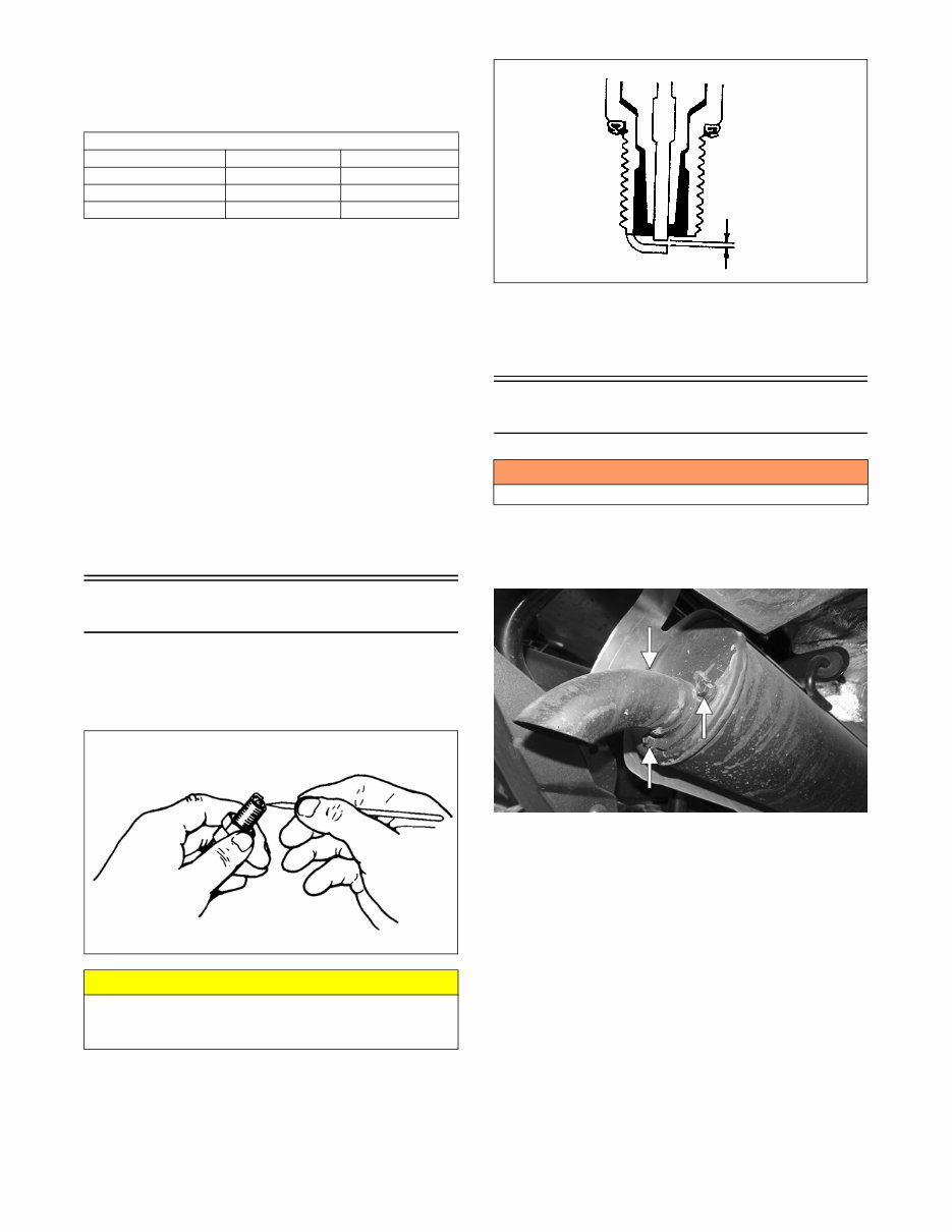
8 5. While holding the throttle lever in the full-open posi- tion, crank the engine over with the electric starter until the gauge shows a peak reading (five to 10 compression strokes). 6. If compression is abnormally low, inspect the following items. A. Verify starter cranks engine over at normal speed (approximately 400 RPM). B. Gauge functioning properly. C. Throttle lever in the full-open position. D. Valve/tappet clearance correct. E. Engine warmed up. F. Intake not restricted. NOTE: To service valves, see Engine/Transmission. 7. Pour 29.5 ml (1 fl oz) of oil into the spark plug hole, reattach the gauge, and retest compression. 8. If compression is now evident, service the top end (see Engine/Transmission). Spark Plug A light brown insulator indicates that a plug and the fuel/air ratio are correct. A white or dark insulator indi- cates that the engine may need to be serviced. To main- tain a hot, strong spark, keep the plug free of carbon. ATV-0051 Adjust the gap to correct specification (see General Infor- mation/Foreword for proper type and gap). Use a feeler gauge to check the gap. ATV0052 A new spark plug should be tightened 1/2 turn once the washer contacts the cylinder head. A used spark plug should be tightened 1/8 - 1/4 turn once the washer con- tacts the cylinder head. Muffler/Spark Arrester 1. Remove the three cap screws securing the spark arrester assembly to the muffler; then loosen and remove the arrester. Account for the gasket and wave washer. XR195A 2. Using a suitable brush, clean the carbon deposits from the screen taking care not to damage the screen. NOTE: If the screen or gasket is damaged in any way, it must be replaced. 3. Install the spark arrester assembly with gasket; then secure with the three cap screws. Tighten to 48 in.-lb. COMPRESSION Model PSI Hot (WOT) PSI Cold (WOT) 500 95-115 N/A 550 120-140 80-120 700 125-145 100-140 CAUTION Before removing a spark plug, be sure to clean the area around the spark plug. Dirt could enter engine when removing or installing the spark plug. ! WARNING Wait until the muffler cools to avoid burns.
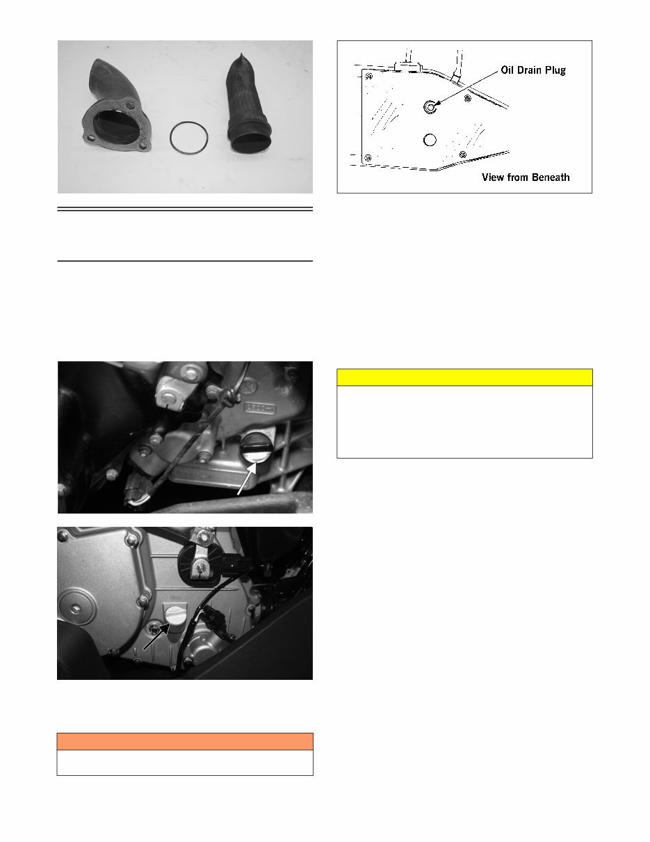
9 XR196 Engine/Transmission Oil - Filter OIL - FILTER The engine should always be warm when the oil is changed so the oil will drain easily and completely. 1. Park the ATV on level ground. 2. Remove the oil level stick/filler plug. CF109M KC372A 3. Remove the drain plug from the bottom of the engine and drain the oil into a drain pan. Account for and discard the drain plug gasket. 733-441A 4. Using the adjustable Oil Filter Wrench and a suitable wrench, remove the old oil filter. Account for and discard the O-ring. NOTE: Clean up any excess oil after removing the filter. 5. Apply oil to the new filter O-ring and check to make sure it is positioned correctly; then install the new oil filter. Tighten securely. 6. Install the engine drain plug with new gasket and tighten to 16 ft-lb. Pour the specified amount of the recommended oil in the filler hole. Install the oil level stick/filler plug. 7. Start the engine (while the ATV is outside on level ground) and allow it to idle for a few minutes. 8. Turn the engine off and wait approximately one min- ute. 9. Remove the oil level stick and wipe it with a clean cloth. 10. Install the oil level stick and thread into the engine case. 11. Remove the oil level stick; the oil level must be within the operating range but not exceeding the upper mark. ! WARNING Use extreme caution when removing the oil drain plug. Hot oil can cause severe injury and skin burns. 550/700 500 CAUTION Any oil used in place of the recommended oil could cause serious engine damage. Do not use oils which contain graphite or molybdenum additives. These oils can adversely affect clutch operation. Also, not recom- mended are racing, vegetable, non-detergent, and cas- tor-based oils.
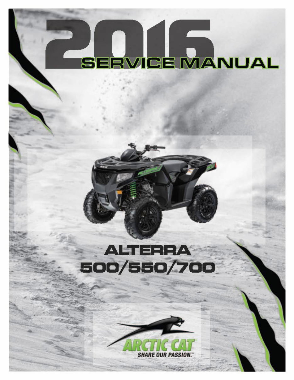
This is a highly detailed OEM service and repair manual specifically designed for the 2016 Artic Cat Alterra 500/550/700 ATV. The manual provides comprehensive, step-by-step instructions and detailed illustrations that are invaluable for both do-it-yourself enthusiasts and experienced mechanics. It covers all crucial areas including general information, periodic maintenance and tune-up, steering and frame controls, engine and transmission, fuel, lubrication and cooling systems, electrical system, drive system, suspension, and more.
Models Covered:
2016 Artic Cat Alterra 500
2016 Artic Cat Alterra 550
2016 Artic Cat Alterra 700
File Format: PDF
Compatibility: All Versions of Windows & Mac
Language: English
Requirements: Adobe Reader & WinZip
This manual offers an economical solution to keeping your ATV operating at its peak. It is available for instant download, providing convenience and saving both time and money.





 Lifetime Access


