TABLE OF CONTENTS Click on the red text to go. Section 1. General Information 2. Periodic Maintenance/Tune-Up 3. Engine/Transmission 4. Fuel/Lubrication/Cooling 5. Electrical System 6. Drive System 7. Suspension 8. Steering/Frame 9. Controls 10. Aids for Maintenance 1 2 3 4 5 6 7 8 9 10
1-1 1 SECTION 1 - GENERAL INFORMATION TABLE OF CONTENTS Specifications .......................................................... 1-2 Break-In Procedure ................................................. 1-2 Gasoline-Oil-Lubricant ............................................ 1-2 Genuine Parts ......................................................... 1-3 Preparation For Storage .......................................... 1-3 Preparation After Storage........................................ 1-3 Back to TOC
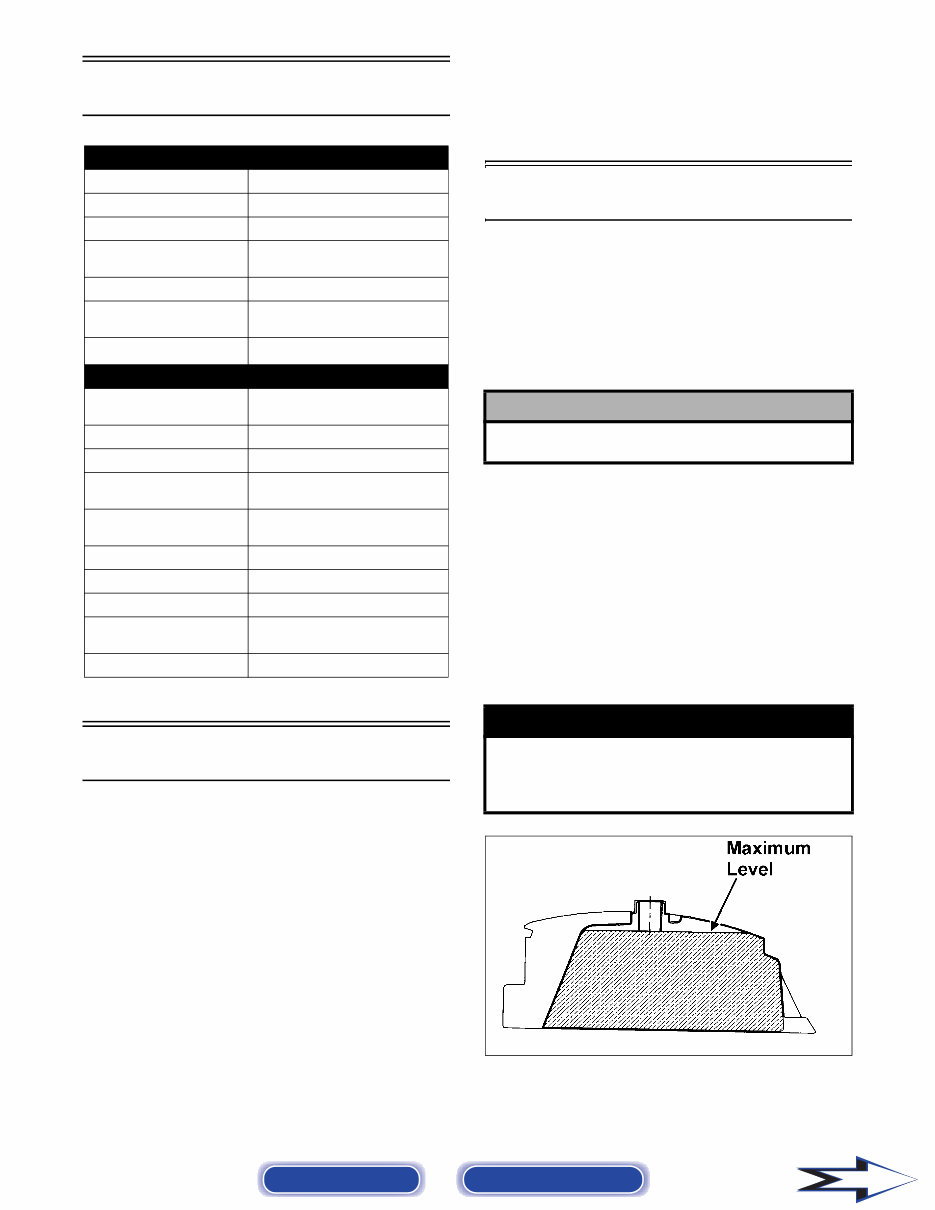
Back to TOC Back to Section TOC Next Specifications* C Length (Overall) HASSIS 146.8 cm (57.8 in.) Height (Overall) 96.2 cm (37.9 in.) Width (Overall) 87.6 cm (34.5 in.) Suspension Travel (Front) (Rear) 71.00 mm (2.8 in.) 73.66 mm (2.9 in.) Wheelbase 97.5 cm (38.38 in.) Tire Size (Front) (Rear) AT20 x 7-8 AT19 x 8-8 Tire Inflation Pressure MIS Dry Weight (Approx) 0.21 kg-cm 2 (3.0 psi) CELLANY 118 kg (260 lb) - DVX 123 kg (271 lb) - Utility Gas Tank Capacity (Rated) 5.5 L (1.4 U.S. gal.) Reserve Capacity 1.3 L (0.34 U.S. gal.) Transmission Lubricant (Recommended) SAE 80W-90 Hypoid Transmission Lubricant Capacity 100 ml (3.4 fl oz) Engine Oil Capacity 0.8 L (0.84 U.S. qt) Gasoline (Recommended) 87 Octane Regular Unleaded Engine Oil (Recommended) 5W-30 Brake Type Front Double Drum/Rear Hydrau- lic Disc w/Brake Lever Locks Starting System Electric w/Kick Start (Emergency) * Specifications subject to change without notice. Break-In Procedure A new ATV and an overhauled ATV engine require a “break-in” period. The first month is most critical to the life of this ATV. Proper operation during this break-in period will help assure maximum life and performance from the ATV. During the first three hours of operation, always use less than 1/2 throttle. Varying the engine RPM dur- ing the break-in period allows the components to “load” (aiding the mating process) and then “unload” (allowing components to cool). Although it is essential to place some stress on the engine components during break-in, care should be taken not to overload the engine too often. When the engine starts, allow it to warm up prop- erly. Idle the engine several minutes until the engine has reached normal operating temperature. Do not idle the engine for excessively long periods of time. After the completion of the break-in period, the engine lubricant should be changed. Other mainte- nance after break-in should include checking of all prescribed adjustments and tightening of all fasten- ers. Gasoline-Oil-Lubricant RECOMMENDED GASOLINE The recommended gasoline to use is 87 minimum octane regular unleaded. In many areas, oxygenates (either ethanol or MTBE) are added to the gasoline. Oxygenated gasolines containing up to 10% ethanol, 5% methane, or MTBE are acceptable gasolines. ! CAUTION Do not use white gas. Only Arctic Cat approved gas- oline additives should be used. RECOMMENDED ENGINE OIL The recommended oil to use is Arctic Cat 4-Cycle Oil. RECOMMENDED TRANSMISSION LUBRICANT The recommended transmission lubricant to use is SAE 80W-90 hypoid. FILLING GAS TANK ! WARNING Always fill the gas tank in a well-ventilated area. Never add gasoline to the ATV gas tank near any open flames or with the engine running or hot. DO NOT SMOKE while filling the gas tank. ATV0049B 1-2
1-3 1 Since gasoline expands as its temperature rises, the gas tank must be filled to its rated capacity only. Expansion room must be maintained in the tank par- ticularly if the tank is filled with cold gasoline and then moved to a warm area. Tighten the gas tank cap securely after filling the tank. Genuine Parts When replacement of parts is necessary, use only genuine Arctic Cat ATV parts. They are precision- made to ensure high quality and correct fit. Refer to the appropriate Illustrated Parts Manual for the cor- rect part number, quantity, and description. Preparation For Storage Arctic Cat recommends the following procedure to prepare the ATV for storage. 1. Clean the seat cushion (cover and base) with a damp cloth and allow to dry. 2. Clean the ATV thoroughly by washing dirt, oil, grass, and other foreign matter from the entire ATV. Allow the ATV to dry thoroughly. DO NOT get water into any part of the engine or air intake. 3. Either drain the gas tank or add Fuel Stabilizer to the gas in the gas tank. Remove the air filter housing cover and air filter. Start the engine and allow it to idle; then using Arctic Cat Engine Preserver, rapidly inject the preserver into the air filter opening for a period of 10 to 20 sec- onds. Install the air filter and housing cover. 4. Drain the carburetor float chamber. 5. Plug the hole in the exhaust system with a clean cloth. 6. Apply light oil to the upper steering post bush- ing and plungers of the shock absorbers. 7. Tighten all nuts, bolts, cap screws, and screws. Make sure rivets holding components together are tight. Replace all loose rivets. Care must be taken that all calibrated nuts, cap screws, and bolts are tightened to specifications (see Section 10). 8. Disconnect the battery cables (negative cable first); then remove the battery, clean the battery posts and cables, and store in a clean, dry area. 9. Store the ATV indoors in a level position. Preparation After Storage Taking the ATV out of storage and correctly prepar- ing it will assure many miles and hours of trouble- free riding. Arctic Cat recommends the following procedure to prepare the ATV. 1. Clean the ATV thoroughly. 2. Clean the engine. 3. Remove the cloth from the exhaust system. 4. Check all control wires and cables for signs of wear or fraying. Replace if necessary. 5. Change the transmission lubricant. 6. Charge the battery; then install. Connect the bat- tery cables making sure to connect the positive cable first. ! WARNING Do not over-fill or overflow gasoline when filling the gas tank. A fire hazard could materialize. Always allow the engine to cool before filling the gas tank. ! CAUTION Prior to storing the ATV, it must be properly serviced to prevent rusting and component deterioration. ! CAUTION If the interior of the air filter housing is dirty, clean the area before starting the engine. ! CAUTION This maintenance-free battery should be charged at the recommended rate every 30 days or permanent damage will result if the battery completely dis- charges. ! CAUTION Avoid storing outside in direct sunlight and avoid using a plastic cover as moisture will collect on the ATV causing rusting. Back to TOC Back to Section TOC Next Back
7. Check the entire brake system (cables, shoes, etc.), and all controls. Adjust or replace if neces- sary. Back to TOC Back to Section TOC Back 8. Check the tire pressure. Inflate to recommended pressure as necessary. 9. Tighten all nuts, bolts, cap screws, and screws making sure all calibrated nuts, cap screws, and bolts are tightened to specifications (see Section 10). 10. Make sure the steering moves freely and does not bind. 11. Check the spark plug. Clean or replace as neces- sary. 1-4
Back to TOC Back to Section TOC Next A = Adjust I = Inspect C = Clean L = Lubricate Periodic Maintenance CH = Charge R = Replace Chart D = Drain T = Tighten Item Initial Service After Break-In (First Mo) Every Day Every Month Every 3 Months Every 6 Months Every Year As Needed Battery I CH I C Fuse I R Air Filter I C* R Engine Compression I Spark Plug I/C R (4000 Mi or 18 Mo) Chassis C*/L* I Gas/Vent Hoses I C, R (2 Years) Fuel Valve I C Throttle Cable I I C/L A, R Carburetor I C/D* C/D* Engine RPM (Idle) I I I/A Engine Oil R I R Valve/Tappet Clearance A A Transmission Lubricant/Level R I Fuel Filter I I R Tires/Air Pressure/Wear I I I/R Steering Components I I R Drive Chain I C*/L* R Suspension (Tie Rods, Protective Boots) I I R Nuts/Bolts/Cap Screws I I/T T Ignition Timing I Brakelight I I R Switches I R Kick Starter I C Handlebar/Grips I R Frame/Welds I l Electrical Connections I I C Complete Brake Systems I I C* L, R Brake Fluid I I R (2 Years) Shock Absorbers I R *Service/Inspect more frequently when operating in adverse conditions. 2-2
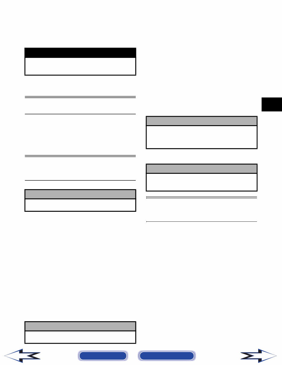
2-3 2 Lubrication Points It is advisable to lubricate certain components peri- odically to ensure free movement. Apply light oil to the components using the following list as refer- ence. A. Throttle Lever Pivot/Cable Ends B. Brake Lever Pivot/Cable Ends C. Brake Cable Ends D. Idle RPM Adjustment Screw (Carburetor) Battery The battery is located under the seat. After being in service, batteries require regular cleaning and recharging in order to deliver peak per- formance and maximum service life. The following procedure is recommended for cleaning and main- taining a sealed battery. Always read and follow instructions provided with battery chargers and bat- tery products. 1. Remove the battery hold-down; then disconnect the battery cables (negative cable first). 2. Remove the battery from the battery compart- ment; then thoroughly wash the battery and bat- tery compartment with soap and water. NOTE: If battery posts, cable ends, or the battery case has a build-up of white/green powder resi- due, apply water and baking soda to neutralize acid; then flush off with warm soapy water. 3. Using a wire brush, clean the battery posts and cable ends removing all corrosive buildup. Replace damaged cables or cable ends. 4. Using a multimeter, test the battery voltage. The meter must read at least 12.5 DC Volts for a fully charged battery. NOTE: At this point if the meter reads as specified, the battery may be returned to service (see step 8). 5. If the meter reads less than specified voltage, charge the battery using the following guide- lines. A. When using an automatic battery charger, always follow the charger manufacturer’s instructions. B. When using a constant-current battery charger, use the following Battery Charging Chart. NOTE: If the battery voltage is 11.5 DC Volts or less, some chargers may “cut off” and fail to charge. If this occurs, connect a fully charged booster battery in parallel (positive to positive and negative to negative) for a short period of time with the charger connected. After 10-15 minutes, disconnect the booster battery leaving the charger connected and the charger should continue to charge. If the charger “cuts off,” replace the bat- tery. 6. After charging the battery for the specified time, remove the battery charger and allow the battery to sit for 1-2 hours. ! WARNING Anytime service is performed on a battery, the fol- lowing must be observed: keep sparks, open flame, cigarettes, or any other flame away. Always wear safety glasses. Protect skin and clothing when hand- ing a battery. When servicing battery in enclosed space, keep the area well-ventilated. ! CAUTION Do not remove seal strip. ! WARNING Battery acid is harmful if it contacts eyes, skin, or clothing. Care must be taken whenever handling a battery. ! CAUTION Never exceed the standard charging rate. ! WARNING An overheated battery could explode causing severe injury or death. Always monitor charging times and charge rates carefully. Stop charging if the battery becomes very warm to the touch. Allow it to cool before resuming charging. Battery Charging Chart (Constant-Current Charger) Battery Voltage (DC) Charge State Charge Time Required (at 1.5-2.0 Amps) 12.5 or more 100% None 12.2-12.4 75%-99% 3-6 hours 12.0-12.2 50%-74% 5-11 hours 11.0-11.9 25%-49% 13 hours (minimum) 11.5 or less 0-24% 20 hours (minimum) Back to TOC Back to Section TOC Next Back
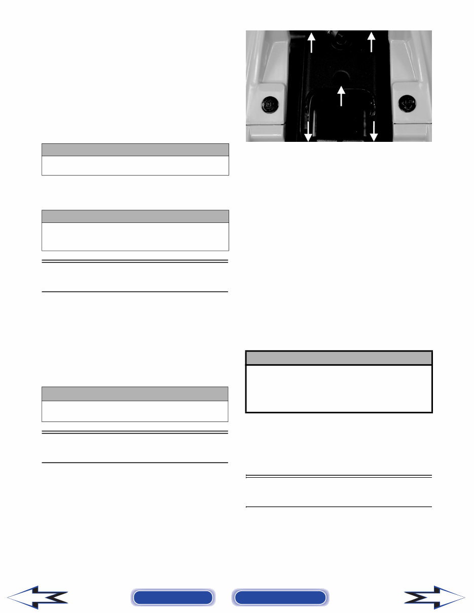
2-4 7. Connect the multimeter and test the battery volt- age. The meter should read at least 12.5 DC Volts. If the voltage is as specified, the battery is ready for service. NOTE: If voltage in step 7 is below specifica- tions, charge the battery an additional 1-5 hours; then retest. 8. Place the battery in the battery compartment; then coat the battery posts and cable ends with a light coat of multi-purpose grease. 9. Connect the battery cables (positive cable first); then install the battery hold-down. Fuse The main (7 amp) fuse is located on the frame near the battery under the seat. NOTE: To remove the fuse, compress the locking tabs on either side of the fuse case and lift out. If there is any type of electrical system failure, always check the fuse first. Air Filter 1. Remove the seat; then remove five screws securing the air filter housing cover. KM032A 2. Remove the air filter housing cover; then pull the filter out of the housing. 3. Fill a wash pan larger than the element with a non-flammable cleaning solvent; then dip the element in the solvent and wash it. NOTE: Foam Filter Cleaner and Foam Filter Oil are available from Arctic Cat. 4. Compress the element by pressing it between the palms of both hands to remove excess sol- vent. Do not twist or wring the element or it will develop cracks. 5. Dry the element. 6. Put the element in a plastic bag; then pour in air filter oil and work the oil into the element. 7. Compress the element to remove excess oil. 8. Clean any dirt or debris from inside the air cleaner. Make sure no dirt enters the carburetor. 9. Install the air filter. Install air filter housing cover and secure with the five screws. Valve/Tappet Clearance To check and adjust valve/tappet clearance, use the following procedure. NOTE: Valve/tappet clearance specifications are for room temperature (approximately 68° F). ! CAUTION Before installing the battery, make sure the ignition switch is in the OFF position. ! CAUTION Connecting cables in reverse (positive to negative and negative to positive) can cause serious damage to the electrical system. ! CAUTION Always replace a blown fuse with a fuse of the same type and rating. ! CAUTION A torn air filter can cause damage to the ATV engine. Dirt and dust may get inside the engine if the ele- ment is torn. Carefully examine the element for tears before and after cleaning it. Replace the element with a new one if it is torn. Back to TOC Back to Section TOC Next Back
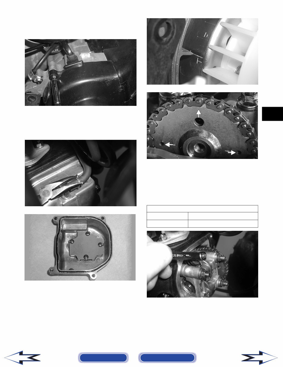
2-5 2 1. Remove the two cap screws and the two self-tapping screws securing the fan shroud; then remove the fan shroud. CD651 2. Remove the breather tube from the valve cover; then remove the four cap screws and remove the valve cover. Account for the O-ring seal and the valve cover. CD654 CD655 3. Remove the spark plug wire and the spark plug; then rotate the engine clockwise to the TDC position on the compression stroke. NOTE: The “T” mark on the rotor/flywheel is aligned with the timing pointer on the crankcase, and intake and exhaust valve adjuster screws must not have pressure on them. The two punch marks on the camshaft gear are aligned with the valve cover surface, and the hole in the timing gear points away from the engine. CD652 CD656A 4. Using a feeler gauge, check each valve tappet clearance. If the clearance is not within specifi- cations, loosen the jam nut and rotate the tappet adjuster screw until the clearance is within spec- ifications. Tighten each jam nut securely after completing the adjustment. CD659 VALVE/TAPPET CLEARANCE Intake 0.1 mm (0.0039 in.) Exhaust 0.1 mm (0.0039 in.) Back to TOC Back to Section TOC Next Back
This Workshop Service Repair Manual provides comprehensive technical information necessary for performing all repairs related to ARTIC CAT 90 ATV models from 2009. It includes detailed instructions for every repair procedure, simplifying all service and repairs.
The manual features easy-to-read exploded views and diagrams, facilitating easy identification, disassembly/re-assembly, accurate adjustment, and correct repairs. Additionally, it contains illustrations, diagrams, specifications, step-by-step instructions, and procedures.
Designed for both professional mechanics and DIY enthusiasts, this Workshop Service Repair Manual is essential for servicing, teardowns, repairs, overhauls, adjustments, and complete specifications.
It is available in .PDF format, compatible with all computers, including PC and Mac systems such as 95, 98, 2000, NT, XP, Vista, Windows 7, and 8.