Arctic Cat 90 Utility ATV 2012 2013 Service Repair Manual
What's Included?
Lifetime Access
Fast Download Speeds
Online & Offline Access
Access PDF Contents & Bookmarks
Full Search Facility
Print one or all pages of your manual
TM SHARE OUR PASSI ON. T A A A A A A V V Manual n Service M S S n v u c a a r M u l a a i e e M S S M n a a r v c ervice S S 0 90 90 X 9 X 9 X X VX VX DV DV X V 9 DVX 90 0 0 D D V V X X 0 DVX 90 90 Utility 0 y 90 ti ity 90 Utility Utility i l i 9 90 0 0 0 U U 90 U 1 TABLE OF CONTENTS General Information ........................................................... 2 Specifications ............................................................... 2 Torque Specifications.................................................... 3 Torque Conversions (ft-lb/N-m) ..................................... 3 Break-In Procedure ...................................................... 3 Gasoline-Oil-Lubricant .................................................. 4 Genuine Parts ............................................................... 4 Preparation For Storage ............................................... 4 Preparation After Storage ............................................. 5 Periodic Maintenance/Tune-Up ......................................... 6 Periodic Maintenance Chart ......................................... 6 Air Filter ........................................................................ 7 Valve/Tappet Clearance ................................................ 7 Testing Engine Compression ........................................ 8 Spark Plug .................................................................... 9 Muffler/Spark Arrester .................................................. 9 Transmission Lubricant ................................................. 9 Engine Oil ................................................................... 10 Headlights................................................................... 11 Brakelight/Taillight ....................................................... 11 Brake Systems............................................................ 12 Replacing Drive Belt ................................................... 14 Adjusting Shift Linkage ............................................... 15 Troubleshooting Brake System ................................... 15 Engine/Transmission ....................................................... 16 Removing Engine/Transmission ................................. 16 Top-Side Components ................................................ 17 Removing Top-Side Components ............................... 18 Servicing Top-Side Components ................................ 20 Installing Top-Side Components ................................. 25 Left-Side Components ................................................ 28 Removing Left-Side Components ............................... 28 Installing Left-Side Components................................. 30 Right-Side Components ............................................. 31 Removing Right-Side Components ............................ 32 Servicing Right-Side Components.............................. 35 Installing Right-Side Components .............................. 36 Center Crankcase Components ................................. 38 Disassembling Crankcase Halves .............................. 38 Servicing Crankcase Components ............................. 39 Assembling Crankcase Half ........................................ 40 Installing Engine/Transmission ................................... 41 Troubleshooting .......................................................... 43 Fuel/Lubrication ............................................................... 45 Carburetor Schematic ................................................. 45 Carburetor ................................................................... 45 Throttle Cable Free-Play ............................................. 49 Engine RPM (Idle) ....................................................... 49 Gas Tank ..................................................................... 50 Gas Tank Valve ........................................................... 51 Gas/Vent Hoses .......................................................... 52 Oil Pump Assembly ..................................................... 52 Oil Screen/Filter .......................................................... 52 Troubleshooting ........................................................... 52 Electrical System.............................................................. 53 Battery ......................................................................... 53 Testing Electrical Components .................................... 54 Timing Sensor ............................................................. 54 CDI/Ignition Coil .......................................................... 54 Stator Coil ................................................................... 54 Choke Circuit ............................................................... 55 Brakelight Switch ......................................................... 55 Fuse ............................................................................ 55 Ignition Coil ................................................................. 55 Ignition Switch ............................................................. 56 Handlebar Control Switches........................................ 56 Magneto Assembly ...................................................... 56 Starter Motor ............................................................... 57 Regulator/Rectifier ...................................................... 57 Ignition Timing ............................................................. 57 Headlights ................................................................... 57 Troubleshooting ........................................................... 57 Drive System..................................................................... 59 Drive Chain/Sprockets................................................. 59 Rear Hub/Drive Axle.................................................... 61 Front Hub .................................................................... 64 Brake Systems ............................................................ 65 Troubleshooting ........................................................... 66 Suspension ....................................................................... 67 Shock Absorbers ......................................................... 67 A-Arm .......................................................................... 68 Swing Arm................................................................... 70 Wheels and Tires ........................................................ 72 Troubleshooting ........................................................... 74 Steering/Frame/Controls.................................................. 75 Steering Post/Handlebar/Tie Rods .............................. 75 Handlebar Grip ............................................................ 78 Handlebar Switch ........................................................ 78 Hand Brake Lever Assemblies .................................... 79 Troubleshooting ........................................................... 82
2 General Information NOTE: Some photographs and illustrations used in this section are used for clarity purposes only and are not designed to depict actual conditions. Specifications Specifications subject to change without notice. CHASSIS Length (Overall) 146.8 cm (57.8 in.) Height (Overall) 96.2 cm (37.9 in.) Width (Overall) 87.6 cm (34.5 in.) Suspension Travel (Front) (Rear) 71.00 mm (2.8 in.) 73.66 mm (2.9 in.) Tire Size (Front) (Rear) AT20 x 7-8 AT19 x 8-8 Tire Inflation Pressure 0.21 kg-cm 2 (3.0 psi) MISCELLANY Spark Plug Type CR7HSA Spark Plug Gap 0.6-0.7 mm (0.024-0.028 in.) Dry Weight (Approx) 118 kg (260 lb) - DVX 120.2 kg (265 lb) - Utility Gas Tank Capacity 5.7 L (1.5 U.S. gal.) Reserve Capacity 1.3 L (0.34 U.S. gal.) Transmission Lubricant (Recommended) SAE 80W-90 Hypoid Transmission Lubricant Capacity 250 ml (8.4 fl oz) Engine Oil Capacity 0.8 L (0.84 U.S. qt) Gasoline (Recommended) 87 Octane Regular Unleaded Engine Oil (Recommended) Arctic Cat ACX All Weather (Synthetic) Brake Type Front Double Drum/Rear Hydraulic Disc w/Brake Lever Locks Headlight 12V/35W Brakelight 12V/5W Starting System Electric w/Kick Start (Emergency) FUEL SYSTEM Carburetor Type Keihin PTE Main Jet 80 Slow Jet 40 Pilot Screw Setting (turns) 1 3/8 Needle Jet 3.4/2.5 Jet Needle NGRA-3 Idle RPM 1700 Needle Valve/Seat 1.6 Float Arm Height 10.2 mm (0.40 in.) Throttle Cable Free-Play (at lever) 6.0 mm (0.25 in.) IGNITION Ignition Timing 28° BTDC (“F” Mark) @ 4000 RPM Ignition Type CDI Spark Plug Cap 4725-5775 ohms Ignition Coil (primary) Resistance (secondary) Less than 1 ohm (terminal to terminal) 2830-3170 ohms (high tension - plug cap removed - to ground) MAGNETO Timing Sensor (peak voltage) (resistance) 1.8-3.8 DC volts (blue/ yellow to ground) 80-160 ohms (blue/yellow to ground) Regulator/Rectifier 12.1-15.2 DC volts@ 3000 RPM (white to black) CDI/Ignition Coil (peak voltage) 190-282 DC volts (black/ yellow to green) Stator Coil (no load) 13.5-16.5 AC volts @3000 RPM (yellow to white) Stator Coil Resistance Less than 1 ohm (yellow to white) Choke Circuit (voltage) 3.5-4.5 AC volts (yellow to green/black) ENGINE Piston Ring End (top) Gap (Installed) (2nd) (oil) 0.15-0.30 mm 0.30-0.45 mm 0.20-0.70 mm Piston Pin Outside Diameter (Min) 12.96 mm Piston Pin Bore (Max) 13.03 mm Piston Skirt/Cylinder Clearance (Max) 0.10 mm Cylinder Head Distortion (Max) 0.05 mm Cylinder Bore Trueness 50.00-50.05 mm Connecting Rod (Small End Inside Diameter) (Max) 13.06 mm Connecting Rod (Small End Deflection) (Max) 0.40 mm Connecting Rod/Crankshaft Clearance (Side to Side) (Max) 0.05 mm Crankshaft (Runout) (Max) 0.10 mm Camshaft Lobe Height (Intake) (Min) 26.33 mm Camshaft Lobe Height (Exhaust) (Min) 25.65 mm Rocker Arm to Shaft Clearance (Max) 0.10 mm Intake Valve Stem to Guide Clearance (Max) 0.06 mm Exhaust Valve Stem to Guide Clearance (Max) 0.08 mm Valve Stem Runout 0.02 mm Valve Face/Seat Width 0.63 mm Valve Face Radial Runout 0.025 mm Crankshaft Web-to-Web Distance 45.15-45.20 mm Oil Pump Outer Rotor to Body Clearance (Max) 0.25 mm Oil Pump Outer to Inner Rotor Clearance (Max) 0.20 mm Oil Pump Rotor End Clearance (Max) 0.12 mm V-Belt Width (Min) 16.5 mm Centrifugal Clutch Housing (Max) 107.5 mm Centrifugal Clutch Lining Thickness (Min) 1.0 mm Driven Pulley Spring Free Length (Min) 154.6 mm Roller Guide Diameter (Min) 15.4 mm Movable Drive Face Collar (Max) 24.06 mm
3 Torque Specifications * w/Red Loctite #271 Torque Conversions (ft-lb/N-m) Break-In Procedure A new ATV and an overhauled ATV engine require a “break-in” period. The first month is most critical to the life of this ATV. Proper operation during this break-in period will help assure maximum life and performance from the ATV. During the first three hours of operation, always use less than 1/2 throttle. Varying the engine RPM during the break-in period allows the components to “load” (aiding the mating process) and then “unload” (allowing compo- nents to cool). Although it is essential to place some stress on the engine components during break-in, care should be taken not to overload the engine too often. When the engine starts, allow it to warm up properly. Idle the engine several minutes until the engine has reached normal operating temperature. Do not idle the engine for excessively long periods of time. After the completion of the break-in period, the engine lubricant should be changed. Other maintenance after break-in should include checking of all prescribed adjust- ments and tightening of all fasteners. EXHAUST COMPONENTS Part Part Bolted To Torque ft-lb Exhaust Pipe Cylinder Head 7 Muffler Frame 32 BRAKE SYSTEM COMPONENTS Brake Banjo-Fitting Caliper 25 Brakeline Hose Master Cylinder 20 Rear Brake Caliper Rear Axle Housing 22 ELECTRICAL COMPONENTS Stator* Stator Plate 8 STEERING COMPONENTS Wheel Front/Rear Hub 30 Front Wheel Hub Spindle Axle 45 Handlebar Cap Lower Clamp 10 Steering Post Outer Bearing Cap Inner Bearing Clamp 20 Steering Post Frame 51 Tie Rod End Steering Post 20 SUSPENSION COMPONENTS Front Shock Absorber Frame/A-Arm 29 Rear Shock Absorber Frame/Swing Arm 29 Swing Arm Frame 50 Swing Arm Rear Axle Housing 29 A-Arm Frame 29 Knuckle A-Arm 29 Tie Rod End Knuckle 25 ENGINE COMPONENTS Oil Drain Plug Crankcase 18 Spark Plug Cylinder Head 9 Cylinder Head (Nut) Cylinder 15 Crankcase Half* Crankcase Half 8 Flywheel* Crankshaft 30 Camshaft Holder Cylinder 15 Stationary Drive Sheave* Crankshaft 27.5 Centrifugal Clutch Housing* Driven Pulley/Centrifugal Clutch 40 Oil Pump Crankcase 7 Oil Pump Gear Oil Pump 7 Oil Screen/Filter Cap Crankcase 10 Cam Chain Tensioner Cylinder 7 Transmission Drain Plug Transmission 18 Cylinder Head (Cap Screw) Crankcase 7 Valve Cover Cylinder Head 7 Spline-Lock Drive Sprocket 8 Engine Mount Engine/Frame 32.5 Intake Pipe Cylinder Head 7 DRIVE TRAIN COMPONENTS Rear Hub Rear Axle Shaft 58 Rear Axle Nut (Inner/Outer)* Rear Axle 86 V-Belt Cover Crankcase 7 Transmission Case Cover Transmission 22 Rear Sprocket Sprocket Retainer 20 ft-lb N-m ft-lb N-m ft-lb N-m ft-lb N-m 1 1.4 26 35.4 51 69.4 76 103.4 2 2.7 27 36.7 52 70.7 77 104.7 3 4.1 28 38.1 53 72.1 78 106.1 4 5.4 29 39.4 54 73.4 79 107.4 5 6.8 30 40.8 55 74.8 80 108.8 6 8.2 31 42.2 56 76.2 81 110.2 7 9.5 32 43.5 57 77.5 82 111.5 8 10.9 33 44.9 58 78.9 83 112.9 9 12.2 34 46.2 59 80.2 84 114.2 10 13.6 35 47.6 60 81.6 85 115.6 11 15 36 49 61 83 86 117 12 16.3 37 50.3 62 84.3 87 118.3 13 17.7 38 51.7 63 85.7 88 119.7 14 19 39 53 64 87 89 121 15 20.4 40 54.4 65 88.4 90 122.4 16 21.8 41 55.8 66 89.8 91 123.8 17 23.1 42 57.1 67 91.1 92 125.1 18 24.5 43 58.5 68 92.5 93 126.5 19 25.8 44 59.8 69 93.8 94 127.8 20 27.2 45 61.2 70 95.2 95 129.2 21 28.6 46 62.6 71 96.6 96 130.6 22 29.9 47 63.9 72 97.9 97 131.9 23 31.3 48 65.3 73 99.3 98 133.3 24 32.6 49 66.6 74 100.6 99 134.6 25 34 50 68 75 102 100 136
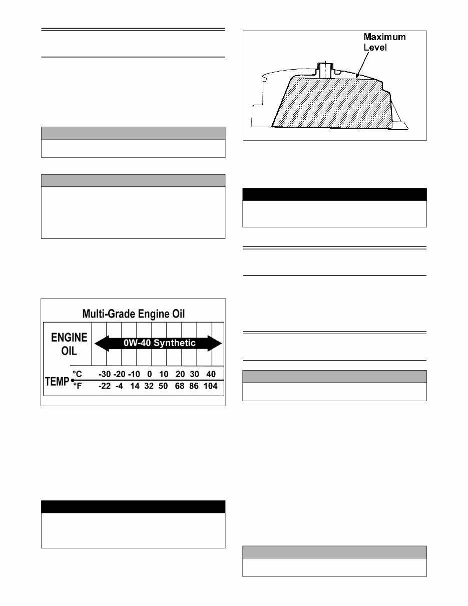
4 Gasoline-Oil-Lubricant RECOMMENDED GASOLINE The recommended gasoline to use is 87 minimum octane regular unleaded. In many areas, oxygenates (either etha- nol or MTBE) are added to the gasoline. Oxygenated gasolines containing up to 10% ethanol, 5% methane, or MTBE are acceptable gasolines. RECOMMENDED ENGINE OIL The recommended oil to use is Arctic Cat ACX All Weather synthetic engine oil, which has been specifically formulated for use in this Arctic Cat engine. Although Arctic Cat ACX All Weather synthetic engine oil is the only oil recommended for use in this engine, use of any API certified SM 0W-40 oil is acceptable. OILCHARTJ RECOMMENDED TRANSMISSION LUBRICANT The recommended lubricant is Arctic Cat Gear Lube or an equivalent gear lube which is SAE approved 80W-90 hypoid. This lubricant meets all the lubrication require- ments of the Arctic Cat ATV front differential and rear drive. FILLING GAS TANK ATV0049B Since gasoline expands as its temperature rises, the gas tank must be filled to its rated capacity only. Expansion room must be maintained in the tank particularly if the tank is filled with cold gasoline and then moved to a warm area. Tighten the gas tank cap securely after filling the tank. Genuine Parts When replacement of parts is necessary, use only genuine Arctic Cat ATV parts. They are precision-made to ensure high quality and correct fit. Refer to the appropriate Illus- trated Parts Manual for the correct part number, quantity, and description. Preparation For Storage Arctic Cat recommends the following procedure to pre- pare the ATV for storage. 1. Clean the seat cushion (cover and base) with a damp cloth and allow to dry. 2. Clean the ATV thoroughly by washing dirt, oil, grass, and other foreign matter from the entire ATV. Allow the ATV to dry thoroughly. DO NOT get water into any part of the engine or air intake. 3. Either drain the gas tank or add Fuel Stabilizer to the gas in the gas tank. Remove the air filter housing cover and air filter. Start the engine and allow it to idle; then using Arctic Cat Engine Preserver, rapidly inject the preserver into the air filter opening for a period of 10 to 20 seconds. Install the air filter and housing cover. CAUTION Do not use white gas. Only Arctic Cat approved gaso- line additives should be used. CAUTION Any oil used in place of the recommended oil could cause serious engine damage. Do not use oils which contain graphite or molybdenum additives. These oils can adversely affect clutch operation. Also, not recom- mended are racing, vegetable, non-detergent, and cas- tor-based oils. ! WARNING Always fill the gas tank in a well-ventilated area. Never add gasoline to the ATV gas tank near any open flames or with the engine running or hot. DO NOT SMOKE while filling the gas tank. ! WARNING Do not over-fill or overflow gasoline when filling the gas tank. A fire hazard could materialize. Always allow the engine to cool before filling the gas tank. CAUTION Prior to storing the ATV, it must be properly serviced to prevent rusting and component deterioration. CAUTION If the interior of the air filter housing is dirty, clean the area before starting the engine.
5 4. Drain the carburetor float chamber. 5. Plug the hole in the exhaust system with a clean cloth. 6. Apply light oil to the upper steering post bushing and plungers of the shock absorbers. 7. Tighten all nuts, bolts, cap screws, and screws. Make sure rivets holding components together are tight. Replace all loose rivets. Care must be taken that all calibrated nuts, cap screws, and bolts are tightened to specifications. 8. Disconnect the battery cables (negative cable first); then remove the battery, clean the battery posts and cables, and store in a clean, dry area. 9. Store the ATV indoors in a level position. Preparation After Storage Taking the ATV out of storage and correctly preparing it will assure many miles and hours of trouble-free riding. Arctic Cat recommends the following procedure to pre- pare the ATV. 1. Clean the ATV thoroughly. 2. Clean the engine. 3. Remove the cloth from the exhaust system. 4. Check all control wires and cables for signs of wear or fraying. Replace if necessary. 5. Change the transmission lubricant. 6. Charge the battery; then install. Connect the battery cables making sure to connect the positive cable first. 7. Check the entire brake system (cables, shoes, etc.), and all controls. Adjust or replace if necessary. 8. Check the tire pressure. Inflate to recommended pressure as necessary. 9. Tighten all nuts, bolts, cap screws, and screws mak- ing sure all calibrated nuts, cap screws, and bolts are tightened to specifications. 10. Make sure the steering moves freely and does not bind. 11. Check the spark plug. Clean or replace as necessary. CAUTION This maintenance-free battery should be charged at the recommended rate every 30 days or permanent damage will result if the battery completely discharges. CAUTION Avoid storing outside in direct sunlight and avoid using a plastic cover as moisture will collect on the ATV caus- ing rusting.
6 Periodic Maintenance/ Tune-Up Tighten all nuts, bolts, and cap screws. Make sure rivets holding components together are tight. Replace all loose rivets. Care must be taken that all calibrated nuts, bolts, and cap screws are tightened to specifications. It is advisable to lubricate certain components periodi- cally to ensure free movement. Apply light oil to the components using the following list as reference. A. Throttle Lever Pivot/Cable Ends B. Brake Lever Pivot/Cable Ends C. Idle RPM Adjustment Screw Periodic Maintenance Chart A = Adjust I = Inspect C = Clean L = Lubricate CH = Charge R = Replace D = Drain T = Tighten *Service/Inspect more frequently when operating in adverse conditions. Item Initial Service After Break-In (First Mo) Every Day Every Month Every 3 Months Every 6 Months Every Year As Needed Battery I CH I C Fuse I R Air Filter I C* R Engine Compression I Spark Plug I/C R (18 Mo) Chassis C*/L* I Gas/Vent Hoses I C, R (2 Years) Gas Tank Valve I C Throttle Cable I I C/L A, R Carburetor I D* D* Engine RPM (Idle) I I I/A Engine Oil R I R Valve/Tappet Clearance A A Transmission Lubricant/ Level R I Fuel Filter I I R Tires/Air Pressure/Wear I I I/R Steering Components I I R Drive Chain I C*/L* R Suspension (Tie Rods, Protective Boots) I I R Nuts/Bolts/Cap Screws I I/T T Ignition Timing I Brakelight I I R Switches I R Kick Starter I C Handlebar/Grips I R Frame/Welds I Electrical Connections I I C Complete Brake Systems I I C* L, R Brake Fluid I I R (2 Years) Shock Absorbers I R
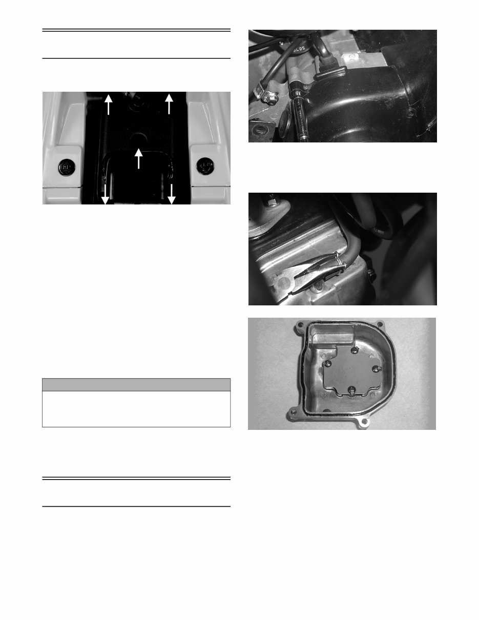
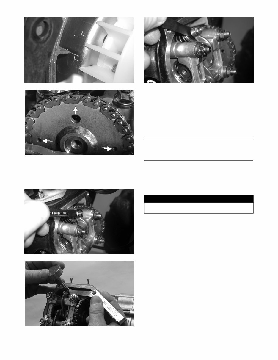
7 Air Filter 1. Remove the seat; then remove five screws securing the air filter housing cover. KM032A 2. Remove the air filter housing cover; then pull the fil- ter out of the housing. 3. Fill a wash pan larger than the element with a non- flammable cleaning solvent; then dip the element in the solvent and wash it. NOTE: Foam Filter Cleaner and Foam Filter Oil are available from Arctic Cat. 4. Compress the element by pressing it between the palms of both hands to remove excess solvent. Do not twist or wring the element or it will develop cracks. 5. Dry the element. 6. Put the element in a plastic bag; then pour in air filter oil and work the oil into the element. 7. Compress the element to remove excess oil. 8. Clean any dirt or debris from inside the air cleaner. Make sure no dirt enters the carburetor. 9. Install the air filter. Install air filter housing cover and secure with the five screws. Valve/Tappet Clearance To check and adjust valve/tappet clearance, use the fol- lowing procedure. NOTE: Valve/tappet clearance specifications are for room temperature (approximately 68° F). 1. Remove the two cap screws and the two self-tapping screws securing the fan shroud; then remove the fan shroud. CD651 2. Remove the breather tube from the valve cover; then remove the four cap screws and remove the valve cover. Account for the O-ring seal and the valve cover. CD654 CD655 3. Remove the spark plug wire and the spark plug; then rotate the engine clockwise to the TDC position on the compression stroke. NOTE: The “T” mark on the rotor/flywheel is aligned with the timing pointer on the crankcase, and intake and exhaust valve adjuster screws must not have pressure on them. The two punch marks on the cam- shaft gear are aligned with the valve cover surface, and the hole in the timing gear points away from the engine. CAUTION A torn air filter can cause damage to the ATV engine. Dirt and dust may get inside the engine if the element is torn. Carefully examine the element for tears before and after cleaning it. Replace the element with a new one if it is torn.
8 CD652 CD656A 4. Using a feeler gauge, check each valve tappet clear- ance. If the clearance is not 0.10 mm, loosen the jam nut and rotate the tappet adjuster screw until the clearance is within specifications. Tighten each jam nut securely after completing the adjustment. CD659 YT170 5. Check the valve/tappet clearance after the jam nut has been tightened to ensure the clearance did not change. CD658 6. Install the valve cover and tighten the four cap screws to 7 ft-lb using a crisscross pattern; then install the breather tube. 7. Install the fan shroud and tighten the two cap screws securely. Tighten the self-tapping screws snug taking care not to strip the plastic cover. 8. Install the spark plug and tighten to 9 ft-lb; then install the spark plug wire. Testing Engine Compression To test engine compression, use the following procedure. 1. Remove the high tension lead from the spark plug. 2. Using compressed air, blow any debris from around the spark plug. 3. Remove the spark plug; then attach the high tension lead to the plug and ground the plug on the cylinder head well away from the spark plug hole. 4. Attach the Compression Tester Kit (p/n 0444-213). NOTE: The engine must be warm and the battery must be fully charged for this test. 5. While holding the throttle lever in the full-open posi- tion, crank the engine over with the electric starter until the gauge shows a peak reading (five to 10 compression strokes). NOTE: Compression should be within a range of 195-230 psi in the full-open throttle position. 6. If compression is abnormally low, inspect the follow- ing items. A. Verify starter cranks engine over. B. Gauge is functioning properly. C. Throttle lever in the full-open position. 7. Pour 29.5 ml (1 fl oz) of oil into the spark plug hole, reattach the gauge, and retest compression. ! WARNING Always wear safety glasses when using compressed air.
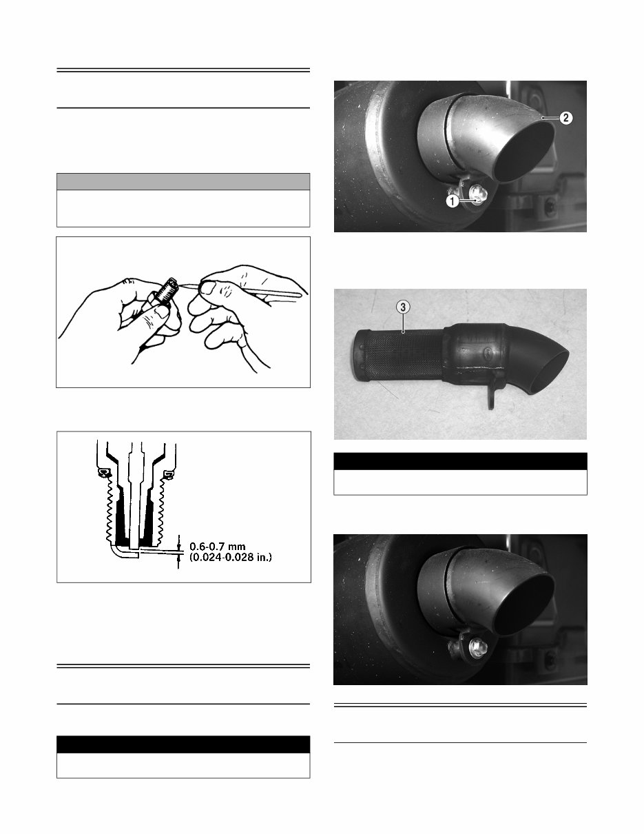
9 8. If compression is now evident, service the piston rings (see Engine/Transmission section). Spark Plug A light brown insulator indicates the plug is correct. A white or dark insulator indicates that the engine may need to be serviced or the carburetor may need to be adjusted. To maintain a hot, strong spark, keep the plug free of carbon. ATV-0051 Adjust the gap to 0.6-0.7 mm (0.024-0.028 in.) for proper ignition. Use a feeler gauge to check the gap. ATV-0052A When installing the spark plug, be sure to tighten it to specifications. A new spark plug should be tightened 1/2 turn once the washer contacts the cylinder head. A used spark plug should be tightened 1/8 - 1/4 turn once the washer contacts the cylinder head. Muffler/Spark Arrester To clean the arrester, use the following procedure. 1. Remove the cap screw (1) securing the spark arrester assembly (2) to the rear of the muffler. Account for a gasket. KM139A 2. Clean the screen (3) with a brush and parts-cleaning solvent. Dry with compressed air. If the screen has any holes or tears, it must be replaced. KM140B 3. Install the spark arrester in the muffler and secure with the cap screw. Tighten securely. KM139 Transmission Lubricant 1. Park the ATV on level ground. CAUTION Before removing the spark plug, be sure to clean the area around the spark plug. Dirt could enter engine when removing or installing the spark plug. ! WARNING Before removing the muffler/spark arrester, wait for it to cool to avoid burns. ! WARNING Before installing the spark arrester, wait for the muffler to cool to avoid burns.
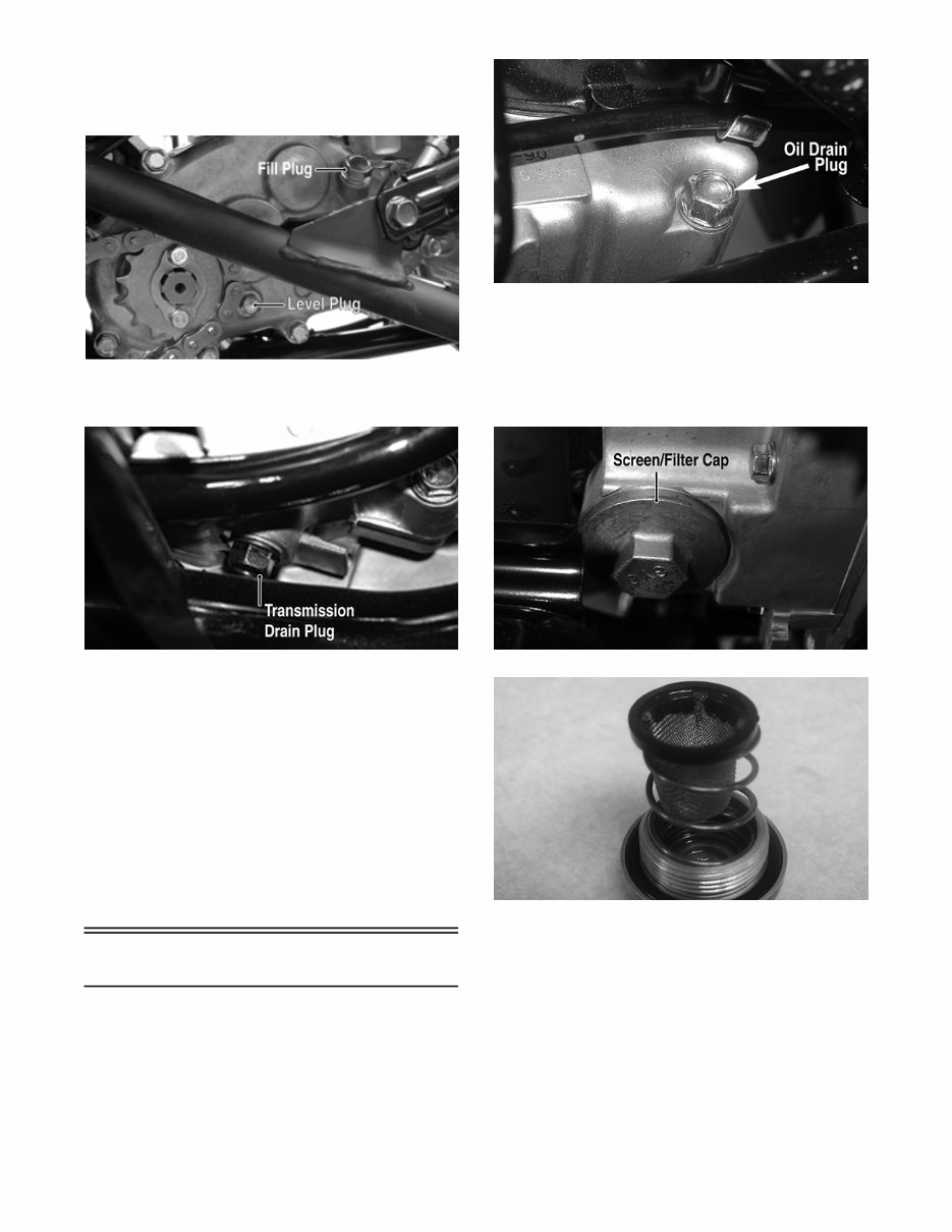
10 2. Remove the level plug from the lower-right side of the transmission; then remove the fill plug from the upper-right side of the transmission. Be careful not to allow contaminates to enter the opening. YT188A 3. Remove the drain plug from the bottom of the trans- mission and drain the lubricant into a drain pan. KM038A 4. Install the drain plug and tighten to 18 ft-lb. Pour the recommended lubricant in the fill hole while observ- ing the oil level hole. Stop pouring if oil is observed at the threads of the oil level hole. Install and tighten the oil level plug. 5. Start the engine (while the ATV is outside on level ground) and drive it a short distance. 6. Turn the engine off and wait approximately one min- ute. Remove the level and recheck the lubricant level. The level should be visible at the level hole. If lubricant is not visible, add recommended lubricant until the level is visible at the level hole. 7. Inspect the area around the drain plug for leaks. Engine Oil 1. Move the ATV outdoors and start and warm up the engine. Shut the engine off; then place a drain pan under the engine oil drain plug located on the left- side rear of the engine under the kick starter. CD634A 2. Remove the oil drain plug and drain the engine oil into the pan; then install the oil drain plug and tighten to 18 ft-lb. 3. Move the drain pan to the right-front of the engine and remove the oil screen/filter cap. Account for a screen, spring, and O-ring. KM040A CD628 4. Clean the oil screen in parts-cleaning solvent using a brush; then install the screen, spring, and cap making sure the O-ring is seated properly in the cap. Tighten to 10 ft-lb.
This is the complete official full factory service repair manual for the Arctic Cat 90 Utility ATV 2012 2013. It provides detailed information on general specifications, periodic maintenance, engine, transmission, fuel system, lubrication, cooling system, electrical system, drive system, suspension, steering, and frame. The manual also includes controls and detailed substeps that expand on repair procedures. It provides notes, cautions, and warnings throughout each chapter, along with numbered instructions and bold figure numbers to guide you through every repair procedure step by step. The manual also contains detailed illustrations, drawings, and photos to guide you through every procedure, along with an enlarged inset to help you identify and examine parts in detail. The numbered table of contents makes it easy to find the information you need fast. Additionally, the manual makes it easy to diagnose and repair problems with your machine's electrical system, as it includes troubleshooting and electrical service procedures combined with detailed wiring diagrams for ease of use.
The Arctic Cat 90 Utility ATV 2012 2013 service manual is available in PDF format, which can work under all PC-based Windows operating systems and Mac as well. It can be saved to your hard drive and burned to CD-ROM. All pages are printable, and there is no need to pay for shipping and wait for the overpriced paper textbook or CD-ROM to arrive via snail mail. The file format is PDF, and the language is English. It is printable without any restriction, and the delivery link will appear on the checkout page after payment is complete. The requirements include Adobe Reader.
This is a full professional quality in-depth service and repair manual for the Arctic Cat 90 Utility ATV 2012 2013. It covers a wide range of topics including general information, specifications, engine removal, wiring diagrams, oil types, periodic maintenance and tune-up procedures, disassembly, reassembly, electrical system, brakes, steering, suspension, servicing information, service data, complete engine service, fuel system service, all factory repair procedures, gearbox, exhaust system, fault finding, and much more.