

2009 Artic Cat 700 H1/H1 Cruiser ATVs OEM Service & Repair Manual
What's Included?
Fast Download Speeds
Online & Offline Access
Access PDF Contents & Bookmarks
Full Search Facility
Print one or all pages of your manual

FOREWORD
This Arctic Cat Service Manual contains service, maintenance, and troubleshooting information for certain 2009
Arctic Cat ATV models (see cover). The complete manual is designed to aid service personnel in service-oriented
applications.
Arctic Cat offers additional publications (when they become available) to aid in servicing other ATV models. To
service models not included in this manual, please refer to the following publications:
• 2009 Y-12 Service Manual
• 2009 T-14 Service Manual
• 2009 DVX 300/250 Utility Service Manual
• 2009 366 Service Manual
• 2009 700 Mud Pro Service Manual Supplement
This manual is divided into sections. Each section covers a specific ATV component or system and, in addition to
the standard service procedures, includes disassembling, inspecting, and assembling instructions. When using this
manual as a guide, the technician should use discretion as to how much disassembly is needed to correct any given
condition.
The service technician should become familiar with the operation and construction of each component or system
by carefully studying the complete manual. This manual will assist the service technician in becoming more aware
of and efficient with servicing procedures. Such efficiency not only helps build consumer confidence but also saves
time and labor.
All Arctic Cat ATV publications and decals display the words Warning, Caution, Note, and At This Point to
emphasize important information. The symbol ! WARNING identifies personal safety-related information.
Be sure to follow the directive because it deals with the possibility of severe personal injury or even death. The
symbol ! CAUTION identifies unsafe practices which may result in ATV-related damage. Follow the direc-
tive because it deals with the possibility of damaging part or parts of the ATV. The symbol NOTE: identifies
supplementary information worthy of particular attention. The symbol AT THIS POINT directs the tech-
nician to certain and specific procedures to promote efficiency and to improve clarity.
At the time of publication, all information, photographs, and illustrations were technically correct. Some photo-
graphs used in this manual are used for clarity purposes only and are not designed to depict actual conditions.
Because Arctic Cat Inc. constantly refines and improves its products, no retroactive obligation is incurred.
All materials and specifications are subject to change without notice.
Keep this manual accessible in the shop area for reference.
Product Service and
Warranty Department
Arctic Cat Inc.
© 2008 Arctic Cat Inc. August 2008
®™ Trademarks of Arctic Cat Inc., Thief River Falls, MN 56701
Back to TOC

TABLE OF CONTENTS
Foreword
Click on the blue text to go.
Section
1. General Information/Specifications
2. Periodic Maintenance
3. Engine/Transmission
4. Fuel/Lubrication/Cooling
5. Electrical System
6. Drive System
7. Suspension
8. Steering/Frame
9. Controls/Indicators
1
2
3
4
5
6
7
8
9

1-1
1
SECTION 1 - GENERAL INFORMATION/
SPECIFICATIONS
TABLE OF
CONTENTS
General Specifications ............................................ 1-2
Torque Specifications .............................................. 1-3
Torque Conversions (ft-lb/N-m) ............................... 1-6
Tightening Torque (General Bolts) .......................... 1-6
Break-In Procedure ................................................. 1-6
Gasoline - Oil - Lubricant ........................................ 1-6
Genuine Parts ......................................................... 1-7
Preparation For Storage .......................................... 1-7
Preparation After Storage........................................ 1-8
Back to TOC

1-2
General Specifications*
* Specifications subject to change without notice.
** One inch below plug threads.
*** At the plug threads.
400 TRV
CHASSIS
Brake Type Hydraulic w/Brake Lever Lock
and Auxiliary Brake
Tire Size Front - 25 x 8-12
Rear - 25 x 10-12
Tire Inflation Pressure 0.35 kg/cm² (5 psi)
MISCELLANY
Gas Tank Capacity (rated) 20.8 L (5.5 U.S. gal.)
Rear Drive Capacity 250 ml (8.5 fl oz)**
Front Differential Capacity 275 ml (9.3 fl oz)***
Engine Oil Capacity 3.3 L (3.5 U.S. qt) - Overhaul
2.8 L (3.0 U.S. qt) - Change
Gasoline (recommended) 87 Octane Regular Unleaded
Engine Oil (recommended) Arctic Cat ACX All Weather
(Synthetic)
Differential/Rear Drive Lubricant SAE Approved 80W-90 Hypoid
Drive Belt Width (minimum) 28.5 mm (1.12 in.)
Brake Fluid DOT 4
Taillight/Brakelight 12V/8W/27W
Headlight 12V/37W (2)
500
CHASSIS
Brake Type Hydraulic w/Brake Lever Lock
and Auxiliary Brake
Tire Size Front - 25 x 8-12
Rear - 25 x 10-12
Tire Inflation Pressure 0.35 kg/cm² (5 psi)
MISCELLANY
Gas Tank Capacity (rated) 24.6 L (6.5 U.S. gal.)
Coolant Capacity 2.9 L (3.0 U.S. qt)
Differential Capacity 275 ml (9.3 fl oz)**
Rear Drive Capacity 250 ml (8.5 fl oz)***
Engine Oil Capacity 3.4 L (3.5 U.S. qt) - Manual
2.5 L (2.6 U.S. qt) - Automatic
Gasoline (recommended) 87 Octane Regular Unleaded
Engine Oil (recommended) Arctic Cat ACX All Weather
(Synthetic)
Differential/Rear Drive Lubricant SAE Approved 80W-90 Hypoid
Drive Belt Width (Automatic)
(minimum)
38 mm (1.33 in.)
Brake Fluid DOT 4
Taillight/Brakelight 12V/8W/27W
Headlight 12V/27W (2)
H1 Models
CHASSIS
Brake Type Hydraulic w/Brake Lever Lock and
Auxiliary Brake
Tire Size Front - 25 x 8-12
Rear - 25 x 10-12
Tire Inflation Pressure 0.35 kg/cm² (5 psi)
MISCELLANY
Gas Tank Capacity (rated) 24.6 L (6.5 U.S. gal.)
20.8 L (5.5 U.S. gal.) - TRV/Cruiser
Coolant Capacity 2.9 L (3.0 U.S. qt)
Differential Capacity 275 ml (9.3 fl oz)**
Rear Drive Capacity 250 ml (8.5 fl oz)***
Engine Oil Capacity 2.5 L (2.6 U.S. qt) - Overhaul
1.9 L (2.0 U.S. qt) - Change
Gasoline (recommended) 87 Octane Regular Unleaded
Engine Oil (recommended) Arctic Cat ACX All Weather (Synthetic)
Differential/Rear Drive
Lubricant
SAE Approved 80W-90 Hypoid
Drive Belt Width (minimum) 35.6 mm (1.40 in.)
Brake Fluid DOT 4
Taillight/Brakelight 12V/8W/27W
Headlight 12V/27W (2)
H2 Models
CHASSIS
Brake Type Hydraulic w/Brake Lever Lock and
Auxiliary Brake
Tire Size Front - 25 x 8-12
Rear - 25 x 10-12
Tire Inflation Pressure 0.35 kg/cm² (5 psi)
MISCELLANY
Gas Tank Capacity (rated) 24.6 L (6.5 U.S. gal.)
20.8 L (5.5 U.S. gal.) - Cruiser
Coolant Capacity 3.3 L (3.5 U.S. qt)
Differential Capacity 275 ml (9.3 fl oz)**
Rear Drive Capacity 250 ml (8.5 fl oz)***
Engine Oil Capacity 2.8 L (3.0 U.S. qt)
Gasoline (recommended) 87 Octane Regular Unleaded
Engine Oil (recommended) Arctic Cat ACX All Weather (Synthetic)
Front Differential/Rear Drive
Lubricant
SAE Approved 80W-90 Hypoid
Drive Belt Width (minimum) 35.6 mm (1.40 in.)
Brake Fluid DOT 4
Taillight/Brakelight 12V/8W/27W
Headlight 12V/27W (2)
Back to TOC Back to Section TOC Next

1-3
1
Torque Specifications
* w/Blue Loctite #243
** w/Red Loctite #271
*** w/Green Loctite #609
EXHAUST COMPONENTS
Part Part Bolted To
Torque
ft-lb N-m
Exhaust Pipe Engine 20 27
Spark Arrester Muffler 48
in.-lb
5.5
ELECTRICAL COMPONENTS
Engine/Harness Ground Cap
Screw
Crankcase 8 11
Coil (500)* Frame 12 16
Coil (EFI Models) Air Filter Housing 7 10
STEERING COMPONENTS
Steering Post Bearing
Housing
Frame 20 27
Steering Post Bearing Flange Frame 20 27
Lower Steering Bearing
Washer Cap Screw***
Steering Post 40 54
Tie Rod End Knuckle/Steering Post 30 41
BRAKE COMPONENTS
Brake Disc* Hub 15 20
Brake Hose Caliper 20 27
Brake Hose Master Cylinder 20 27
Brake Hose Auxiliary Brake Cylinder 20 27
Master Cylinder (Rear) Frame 12 16
Hydraulic Caliper Knuckle 20 27
Master Cylinder Clamp Master Cylinder 6 8
Brake Pedal Brake Pedal Axle 25 34
CHASSIS COMPONENTS
Footrest Frame (8 mm) 20 27
Footrest Frame (10 mm) 40 54
SUSPENSION COMPONENTS (Front)
A-Arm (400/500/H1 Models) Frame 35 47
A-Arm (H2 Models) Frame 50 68
Knuckle Ball Joint 35 47
Shock Absorber Frame 35 47
Shock Absorber Upper A-Arm 35 47
Knuckle A-Arm 35 47
SUSPENSION COMPONENTS (Rear)
Shock Absorber (Upper) Frame 35 47
Shock Absorber (Upper) (H2
Models)
Frame 50 68
Shock Absorber (Lower) Lower A-Arm 20 27
A-Arm Frame 35 47
A-Arm (H2 Models) Frame 50 68
Knuckle A-Arm 35 47
Knuckle (H2 Models) A-Arm 50 68
DRIVE TRAIN COMPONENTS
(400 TRV)
Part Part Bolted To
Torque
ft-lb N-m
Engine Mounting Through-Bolt Frame 38 52
Front Differential Frame/Differential
Bracket
38 52
Output Flange Rear Flange
Output Joint
20 27
Pinion Housing Differential
Housing
23 31
Differential Housing Cover*** Differential
Housing
23 31
Drive Bevel Gear Nut** Shaft 59 80
Driven Bevel Gear Nut** Driven Shaft 59 80
Lock Collar Differential
Housing
125 169
Hub Nut Shaft/Axle (max) 200 272
Oil Drain Plug Front Differential/
Rear Drive
45 in.-lb 5
Oil Fill Plug Front Differential/
Rear Drive
16 22
Oil Drain Plug Engine 20 27
Rear Drive Input Shaft/Housing Differential
Housing
23 31
Wheel Hub 40 54
Rear Drive Gear Case Frame 38 52
Engine Output Shaft** Rear Gear Case
Input Flange
20 27
DRIVE TRAIN COMPONENTS
(500 - Manual Transmission)
Engine (Lower Rear/Front) Frame 40 54
Front Differential Frame/Differential
Bracket
38 52
Pinion Housing Differential
Housing
23 31
Differential Housing Cover*** Differential
Housing
23 31
Drive Bevel Gear Nut*** Shaft 72 98
Lock Collar Differential
Housing
125 169
Hub Nut Shaft/Axle (max) 200 272
Oil Drain Plug Front Differential/
Rear Drive
45 in.-lb 5
Oil Fill Plug Front Differential/
Rear Drive
16 22
Oil Drain Plug Engine 16 22
Inspection Plug Front Differential/
Rear Drive
48 in.-lb 5.5
Wheel Hub 40 54
Rear Drive Input Shaft/Housing Differential
Housing
23 31
Rear Drive Gear Case Frame 45 61
Engine Output Shaft** Rear Gear Case
Input Flange
20 27
Back to TOC Back to Section TOC Next Back

1-4
* w/Blue Loctite #243
** w/Red Loctite #271
*** w/Green Loctite #609
DRIVE TRAIN COMPONENTS
(500 - Automatic Transmission/H1 Models)
Part Part Bolted To
Torque
ft-lb N-m
Engine Mounting Through-Bolt Frame 40 54
Engine (TRV) Engine Cradle 40 54
Engine Cradle (TRV)** Rubber Mount 25 34
Rubber Mount (TRV) Frame Bracket 35 47
Front Differential* Frame/Differential
Bracket
38 52
Output Flange Rear Flange
Output Joint
20 27
Pinion Housing Differential Housing 23 31
Differential Housing Cover*** Differential Housing 23 31
Drive Bevel Gear Nut*** Shaft 72 98
Differential Gear Case*** Hub 19 26
Lock Collar Differential Housing 125 169
Hub Nut Shaft/Axle (max) 200 272
Oil Drain Plug Front Differential/
Rear Drive
45 in.-lb 5
Oil Fill Plug Front Differential/
Rear Drive
16 22
Oil Drain Plug Engine 16 22
Rear Drive Input Shaft/
Housing
Differential Housing 23 31
Wheel Hub 40 54
Rear Drive Gear Case Frame 38 52
Engine Output Shaft ** Rear Gear Case
Input Flange
20 27
DRIVE TRAIN COMPONENTS
(H2 Models)
Engine Mount (Rear) Frame 45 61
Front Differential Frame/Differential
Bracket
38 52
Rear Gear Case Frame 38 52
Pinion Housing Differential Housing 23 31
Differential Housing Cover*** Differential Housing 23 31
Lock Collar Differential Housing 125 169
Hub Nut Shaft/Axle (max) 200 272
Oil Drain Plug Front Differential/
Rear Drive
45 in.-lb 5
Oil Fill Plug Front Differential/
Rear Drive
16 22
Oil Drain Plug Engine 16 22
Wheel Hub 40 54
Rear Drive Input Shaft/
Housing
Differentail Housing 23 31
Rear Output Drive Flange Rear Yoke Flange 20 27
Shift Cam Stopper Shift Stopper 8 11
Shift Cam Plate Shift Cam Shaft 8 11
Shifter Housing Crankcase 8 11
Engine Output Shaft** Rear Gear Case
Input Flange
20 27
ENGINE/TRANSMISSION
(400 TRV)
Part Part Bolted To
Torque
ft-lb N-m
Clutch Shoe** Crankshaft 147 199
Clutch Cover/Housing
Assembly
Crankcase 8 11
Left-Side Cover Crankcase 8 11
Crankcase Half (6 mm) Crankcase Half 10 13.5
Crankcase Half (8 mm) Crankcase Half 21 28
Cylinder Nut Crankcase Half 8 11
Cylinder Head (Cap Screw) Crankcase 28 38
Cylinder Head (6 mm) Cylinder 8 11
Cylinder Head (8 mm) Cylinder 20 27
Cylinder Head Cover Cylinder Head 8 11
Oil Pump Drive Gear** Crankshaft 63 86
Driven Pulley Nut** Driveshaft 147 199
Ground Cable Engine 8 11
Output Shaft Flange Nut Output Shaft 59 80
Magneto Rotor Nut Crankshaft 107 146
Cam Sprocket** Camshaft 11 15
Starter Motor Crankcase 8 11
V-Belt Cover Crankcase 8 11
Valve Adjuster Jam Nut Valve Adjuster 7 9.5
Oil Fitting Engine 8 11
Oil Pump* Crankcase 8 11
Movable Drive Face Nut** Clutch Shaft 147 199
Oil Cooler Hose Clamps Engine/Oil Cooler 30 in.-lb 3.4
ENGINE/TRANSMISSION
(500 - Manual Transmission)
Clutch Shoe Crankshaft 94 127
Clutch Sleeve Hub Countershaft 72 98
Crankcase Half (6 mm) Crankcase Half 8 11
Crankcase Half (8 mm) Crankcase Half 16 22
Cylinder Head (Cap Screw) Cylinder 28 38
Cylinder Head (6 mm Nut) Cylinder 8 11
Cylinder Head (8 mm Nut) Cylinder 18 24
Cylinder Head Cover Cylinder Head 7 9.5
Left-Side Cover Crankcase Half 8 11
Oil Pump Drive Gear** Crank Balancer Shaft 36 49
Oil Strainer Cap Strainer 16 22
Oil Pump* Crankcase 7 9.5
Output Shaft Gear Output Shaft 72 98
Rear Output Shaft Output Joint 20 27
Recoil Starter Left-Side Cover 6 8
Starter Motor Crankcase 8 11
Reverse Cam Stopper
Housing
Crankcase 16 22
Right-Side Cover Crankcase 8 11
Magneto Rotor Nut Crankshaft 116 157
Shift Stop Housing Crankcase 16 22
Cam Sprocket** Camshaft 11 15
Starter Cup Crankshaft 25 34
Movable Drive Face Nut** Driveshaft 72 98
Engine Damper Thermostat Housing 7 9.5
Back to TOC Back to Section TOC Next Back

1-5
1
* w/Blue Loctite #243
** w/Red Loctite #271
*** w/Green Loctite #609
ENGINE/TRANSMISSION
(500 - Automatic Transmission)
Part Part Bolted To
Torque
ft-lb N-m
Clutch Shoe** Crankshaft 94 127
Clutch Cover/Housing
Assembly
Crankcase 8 11
Crankcase Half (6 mm) Crankcase Half 8 11
Crankcase Half (8 mm) Crankcase Half 16 22
Cylinder Head (Cap Screw) Crankcase 28 38
Cylinder Head (6 mm) Cylinder 8 11
Cylinder Head (8 mm) Cylinder 18 24
Cylinder Head Cover Cylinder Head 7 9.5
Driven Pulley Nut** Driveshaft 80 110
Ground Wire Engine 8 11
Magneto Cover Crankcase 8 11
Movable Drive Face Nut** Fixed Drive Face 72 98
Oil Pump Drive Gear** Crank Balancer
Shaft
36 49
Output Shaft Flange Nut Output Shaft 72 98
Recoil Starter Left-Side Cover 6 8
Magneto Rotor Nut Crankshaft 116 157
Cam Sprocket** Camshaft 10 13.5
Starter Cup Crankshaft 25 34
Starter Motor Crankcase 8 11
V-Belt Cover Crankcase 8 11
Valve Adjuster Jam Nut Valve Adjuster 7 9.5
Oil Pump Crankcase 7 9.5
Drive Pulley Nut** Clutch Shaft 80 110
ENGINE/TRANSMISSION
(H1 Models)
Clutch Shoe** Crankshaft 221 300
Clutch Cover/Housing
Assembly
Crankcase 8 11
Crankcase Half (6 mm) Crankcase Half 8 11
Crankcase Half (8 mm) Crankcase Half 20 27
Cylinder Head (Cap Screw) Crankcase 40 54
Cylinder Head (6 mm) Cylinder 8 11
Cylinder Head (8 mm) Cylinder 18 24
Cylinder Head Cover Cylinder Head 8.5 11.5
Driven Pulley Nut Driveshaft 80 108
Ground Wire Engine 8 11
Magneto Cover Crankcase 8 11
Oil Pump Drive Gear** Crank Balancer
Shaft
63 85
Output Shaft Nut Output Shaft 59 80
Outer Magneto Cover Left-Side Cover 6 8
Magneto Rotor Nut Crankshaft 107 145
Cam Sprocket** Camshaft 10 13.5
Starter Motor Crankcase 8 11
V-Belt Cover Clutch Cover 8 11
Drive Pulley Nut** Clutch Shaft 165 224
Movable Drive Face Nut** Clutch Shaft 165 224
Output Yoke Nut Driven Output
Shaft
74 100
ENGINE/TRANSMISSION
(H2 Models)
Part Part Bolted To
Torque
ft-lb N-m
Clutch Shoe** Crankshaft 221 300
Clutch Cover/Housing Assembly Crankcase 8 11
Crankcase Half Crankcase Half 8 11
Crankcase Lower Cover (6 mm) Crankcase 8 11
Crankcase Lower Cover (8 mm) Crankcase 20 27
Cylinder Head (Cap Screw) Crankcase 40 54
Cylinder Head (6 mm) Cylinder 8 11
Cylinder Head (8 mm) Cylinder 18 24
Cylinder Head Cover Cylinder Head 8.5 11.5
Driven Pulley Nut** Driveshaft 80 108
Ground Wire Engine 8 11
Magneto Cover Crankcase 8 11
Oil Filler Cover Crankcase 8 11
Speed Sensor Housing Crankcase 8 11
Starter Motor Crankcase 8 11
V-Belt Housing Crankcase 8 11
Intake Manifold Cylinder 8 11
Output Shaft Nut Output Shaft 59 80
Rotor/Flywheel Nut Crankshaft 107 145
Cam Sprocket** Camshaft 10 13.5
V-Belt Cover Clutch Cover 8 11
Movable Drive Face Nut** Clutch Shaft 165 224
Oil Pump Cover* Crankcase 8 11
Oil Strainer Cap Crankcase 8 11
Shift Cam Stopper Crankcase 8 11
Shift Cam Stopper Spring Shift Cam Stopper 8 11
Shift Cam Plate Shift Cam Shaft 8 11
Shifter Housing Crankcase 8 11
Output Yoke Nut Driven Output Shaft 74 100
Back to TOC Back to Section TOC Next Back
1-6
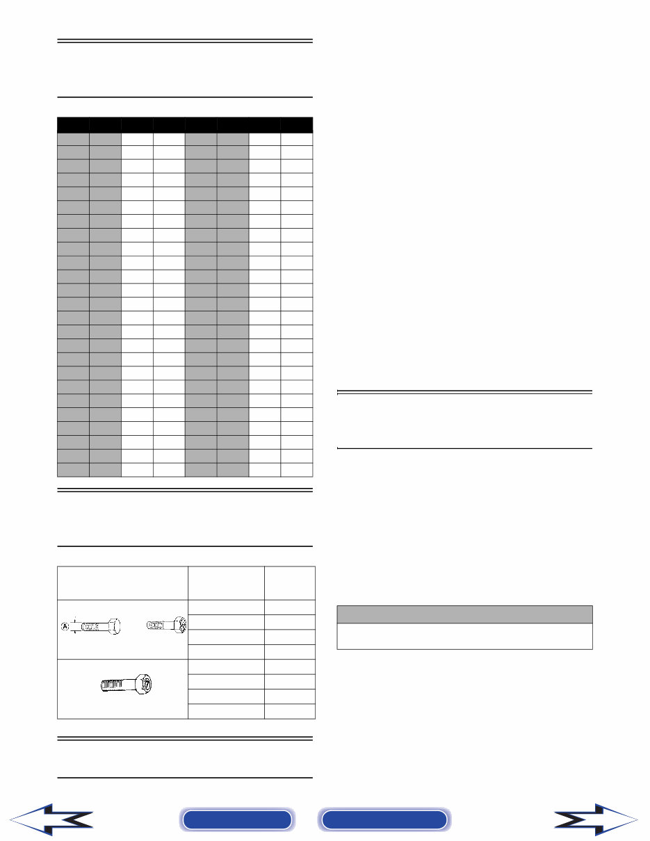
Torque Conversions
(ft-lb/N-m)
Tightening Torque
(General Bolts)
Break-In Procedure
A new ATV and an overhauled ATV engine require a
“break-in” period. The first 10 hours (or 200 miles) are
most critical to the life of this ATV. Proper operation
during this break-in period will help assure maximum
life and performance from the ATV.
During the first 10 hours (or 200 miles) of operation,
always use less than 1/2 throttle. Varying the engine
RPM during the break-in period allows the compo-
nents to “load” (aiding the mating process) and then
“unload” (allowing components to cool). Although it
is essential to place some stress on the engine compo-
nents during break-in, care should be taken not to
overload the engine too often. Do not pull a trailer or
carry heavy loads during the 10-hour break-in period.
When the engine starts, allow it to warm up properly.
Idle the engine several minutes until the engine has
reached normal operating temperature. Do not idle the
engine for excessively long periods of time.
During the break-in period, a maximum of 1/2 throttle
is recommended; however, brief full-throttle accelera-
tions and variations in driving speeds contribute to
good engine break-in.
After the completion of the break-in period, the engine
oil and oil filter should be changed. Other maintenance
after break-in should include checking of all pre-
scribed adjustments and tightening of all fasteners.
Gasoline - Oil -
Lubricant
RECOMMENDED GASOLINE
The recommended gasoline to use is 87 minimum
octane regular unleaded. In many areas, oxygenates
(either ethanol or MTBE) are added to the gasoline.
Oxygenated gasolines containing up to 10% ethanol,
5% methane, or 5% MTBE are acceptable gasolines.
When using ethanol blended gasoline, it is not neces-
sary to add a gasoline antifreeze since ethanol will pre-
vent the accumulation of moisture in the fuel system.
ft-lb N-m ft-lb N-m ft-lb N-m ft-lb N-m
1 1.4 26 35.4 51 69.4 76 103.4
2 2.7 27 36.7 52 70.7 77 104.7
3 4.1 28 38.1 53 72.1 78 106.1
4 5.4 29 39.4 54 73.4 79 107.4
5 6.8 30 40.8 55 74.8 80 108.8
6 8.2 31 42.2 56 76.2 81 110.2
7 9.5 32 43.5 57 77.5 82 111.5
8 10.9 33 44.9 58 78.9 83 112.9
9 12.2 34 46.2 59 80.2 84 114.2
10 13.6 35 47.6 60 81.6 85 115.6
11 15 36 49 61 83 86 117
12 16.3 37 50.3 62 84.3 87 118.3
13 17.7 38 51.7 63 85.7 88 119.7
14 19 39 53 64 87 89 121
15 20.4 40 54.4 65 88.4 90 122.4
16 21.8 41 55.8 66 89.8 91 123.8
17 23.1 42 57.1 67 91.1 92 125.1
18 24.5 43 58.5 68 92.5 93 126.5
19 25.8 44 59.8 69 93.8 94 127.8
20 27.2 45 61.2 70 95.2 95 129.2
21 28.6 46 62.6 71 96.6 96 130.6
22 29.9 47 63.9 72 97.9 97 131.9
23 31.3 48 65.3 73 99.3 98 133.3
24 32.6 49 66.6 74 100.6 99 134.6
25 34 50 68 75 102 100 136
Type of Bolt
Thread Diameter
A (mm)
Tightening
Torque
(Conventional or 4 Marked Bolt) 5 12-36 in.-lb
6 36-60 in.-lb
8 7-11 ft-lb
10 16-25 ft-lb
(7 Marked Bolt) 5 24-48 in.-lb
6 6-8 ft-lb
8 13-20 ft-lb
10 29-43 ft-lb
! CAUTION
Do not use white gas. Only Arctic Cat approved gaso-
line additives should be used.
Back to TOC Back to Section TOC Next Back
1-7
1
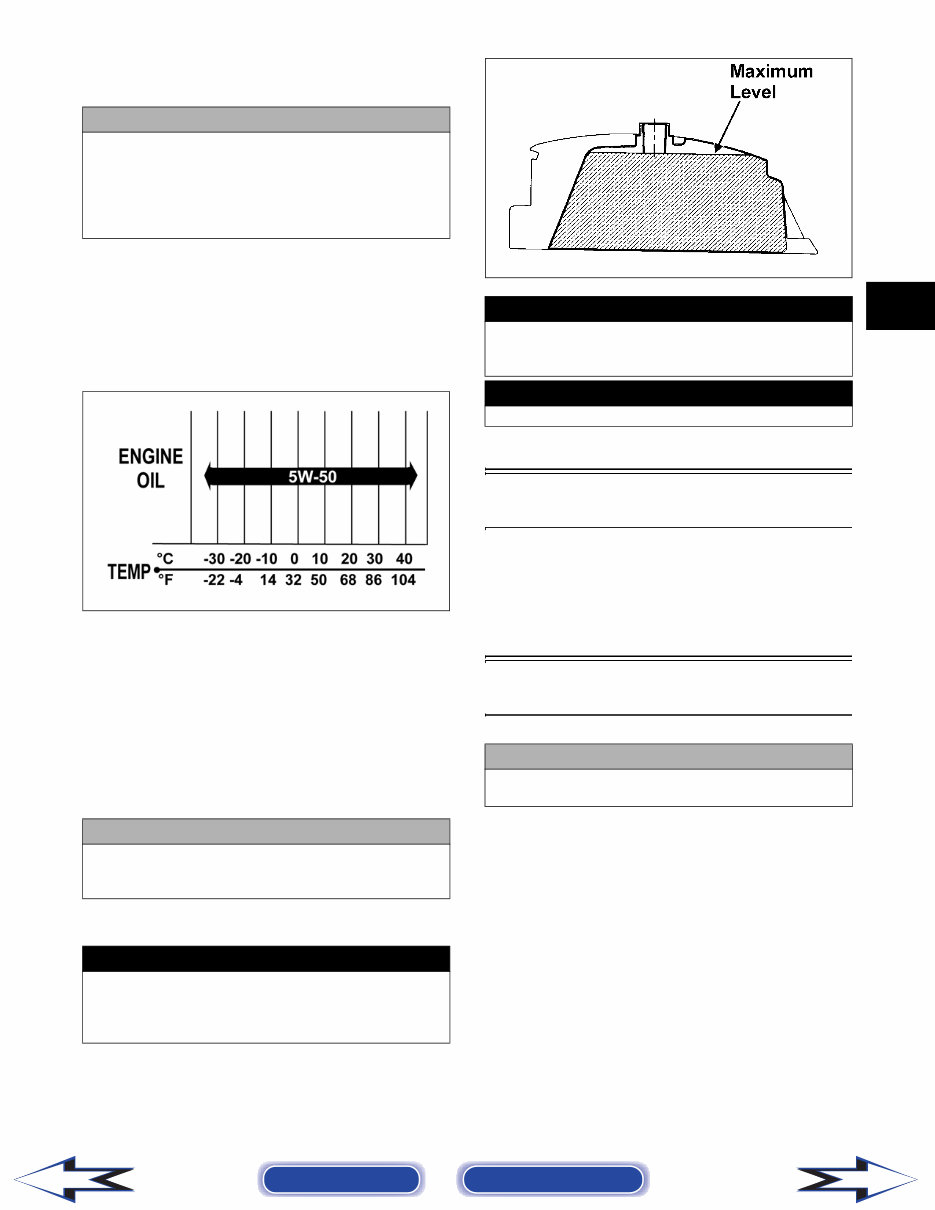
RECOMMENDED ENGINE/
TRANSMISSION OIL
The recommended oil to use is Arctic Cat ACX All
Weather synthetic engine oil, which has been specifi-
cally formulated for use in this Arctic Cat engine.
Although Arctic Cat ACX All Weather synthetic
engine oil is the only oil recommended for use in this
engine, use of any API certified SM 5W-50 oil is
acceptable.
OILCHARTI
RECOMMENDED FRONT
DIFFERENTIAL/REAR DRIVE
LUBRICANT
The recommended lubricant is Arctic Cat Gear Lube
or an equivalent gear lube which is SAE approved
80W-90 hypoid. This lubricant meets all of the lubrica-
tion requirements of the Arctic Cat ATV front differen-
tials and rear drives.
FILLING GAS TANK
Since gasoline expands as its temperature rises, the gas
tank must be filled to its rated capacity only. Expan-
sion room must be maintained in the tank particularly
if the tank is filled with cold gasoline and then moved
to a warm area.
ATV0049B
Tighten the gas tank cap securely after filling the tank.
Genuine Parts
When replacement of parts is necessary, use only gen-
uine Arctic Cat ATV parts. They are precision-made to
ensure high quality and correct fit. Refer to the appro-
priate Illustrated Parts Manual for the correct part
number, quantity, and description.
Preparation For Storage
Arctic Cat recommends the following procedure to
prepare the ATV for storage.
1. Clean the seat cushion (cover and base) with a
damp cloth and allow it to dry.
2. Clean the ATV thoroughly by washing dirt, oil,
grass, and other foreign matter from the entire
ATV. Allow the ATV to dry thoroughly. DO NOT
get water into any part of the engine or air intake.
3. Either drain the gas tank or add Fuel Stabilizer to
the gas in the gas tank. Remove the air filter hous-
ing cover and air filter. Start the engine and allow
it to idle; then using Arctic Cat Engine Storage
Preserver, rapidly inject the preserver into the air
filter opening for a period of 10 to 20 seconds;
then stop the engine. Install the air filter and hous-
ing cover.
! CAUTION
Any oil used in place of the recommended oil could
cause serious engine damage. Do not use oils which
contain graphite or molybdenum additives. These oils
can adversely affect clutch operation. Also, not recom-
mended are racing, vegetable, non-detergent, and cas-
tor-based oils.
! CAUTION
Any lubricant used in place of the recommended lubri-
cant could cause serious front differential/rear drive
damage.
! WARNING
Always fill the gas tank in a well-ventilated area. Never
add fuel to the ATV gas tank near any open flames or
with the engine running. DO NOT SMOKE while filling
the gas tank.
! WARNING
Do not overflow gasoline when filling the gas tank. A
fire hazard could materialize. Always allow the engine
to cool before filling the gas tank.
! WARNING
Do not over-fill the gas tank.
! CAUTION
Prior to storing the ATV, it must be properly serviced
to prevent rusting and component deterioration.
Back to TOC Back to Section TOC Next Back

1-8
4. On carbureted models, drain the carburetor float
chamber.
5. Plug the exhaust hole in the exhaust system with a
clean cloth.
6. Apply light oil to the upper steering post bushing
and plungers of the shock absorbers.
7. Tighten all nuts, bolts, cap screws, and screws.
Make sure rivets holding components together are
tight. Replace all loose rivets. Care must be taken
that all calibrated nuts, cap screws, and bolts are
tightened to specifications.
8. On liquid-cooled models, fill the cooling system to
the bottom of the stand pipe in the radiator neck
with properly mixed coolant.
9. Disconnect the battery cables; then remove the
battery, clean the battery posts and cables, and
store in a clean, dry area.
10. Store the ATV indoors in a level position.
Preparation After
Storage
Taking the ATV out of storage and correctly preparing
it will assure many miles and hours of trouble-free
riding. Arctic Cat recommends the following proce-
dure to prepare the ATV.
1. Clean the ATV thoroughly.
2. Clean the engine. Remove the cloth from the
exhaust system.
3. Check all control wires and cables for signs of
wear or fraying. Replace if necessary.
4. Change the engine/transmission oil and filter.
5. On liquid-cooled models, check the coolant level
and add properly mixed coolant as necessary.
6. Charge the battery; then install. Connect the bat-
tery cables.
7. Check the entire brake systems (fluid level, pads,
etc.), all controls, headlights, taillight, brakelight,
and headlight aim; adjust or replace as necessary.
8. Tighten all nuts, bolts, cap screws, and screws
making sure all calibrated nuts, cap screws, and
bolts are tightened to specifications.
9. Check tire pressure. Inflate to recommended pres-
sure as necessary.
10. Make sure the steering moves freely and does not
bind.
11. Check the spark plug(s). Clean or replace as nec-
essary.
! CAUTION
If the interior of the air filter housing is dirty, clean the
area before starting the engine.
! CAUTION
Avoid storing outside in direct sunlight and avoid
using a plastic cover as moisture will collect on the
ATV causing rusting.
! CAUTION
The ignition switch must be in the OFF position prior
to installing the battery or damage may occur to the
ignition system.
! CAUTION
Connect the positive battery cable first; then the nega-
tive.
Back to TOC Back to Section TOC Back
You're Reading a Preview
What's Included?
Fast Download Speeds
Online & Offline Access
Access PDF Contents & Bookmarks
Full Search Facility
Print one or all pages of your manual
$39.99
Viewed 44 Times Today


Secure transaction
What's Included?
Fast Download Speeds
Online & Offline Access
Access PDF Contents & Bookmarks
Full Search Facility
Print one or all pages of your manual
$39.99
- The 2009 Arctic Cat 700 H1/H1 Cruiser ATVs Service & Repair Manual offers detailed guidance for servicing and maintaining these ATV models.
- It covers key systems such as engine diagnostics, transmission maintenance, and electrical troubleshooting with technical data directly from Arctic Cat.
- The manual includes comprehensive diagrams, precise torque specifications, and clear step-by-step instructions for disassembling, inspecting, and reassembling components.
- Routine maintenance tasks like oil changes, brake adjustments, and drive belt inspections are detailed with comprehensive procedures.
- Wiring diagrams and troubleshooting charts are provided to facilitate accurate diagnosis of electrical issues.
- Designed for both certified technicians and DIY enthusiasts, this manual empowers users to confidently manage routine maintenance and complex repairs on the 2009 Arctic Cat 700 H1/H1 Cruiser ATV.
- It offers detailed technical information and clear instructions to ensure optimal performance and long-term reliability.
- Format: PDF
- Language: English
- Compatibility: Compatible with various electronic devices including PC, Mac, Android, and Apple devices.
- Requirements: Adobe Reader (free)


