Yamaha Electric Gas Golf Cart Car G11 G14 G16 G19 G20 Shop S
What's Included?
Lifetime Access
Fast Download Speeds
Online & Offline Access
Access PDF Contents & Bookmarks
Full Search Facility
Print one or all pages of your manual
~ YAMAHA YAMAHA GOLF-CAR COMPANY G22 A/E SERVICE MANUAL UT-19616-22-05
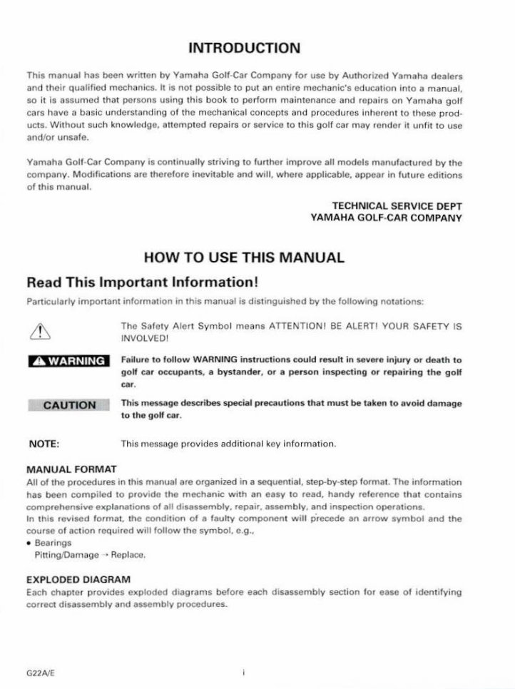
INTRODUCTION Th1s manual has been written by Yamaha Golf-Car Company for use by Authorized Yamaha dealers and their qualified mechanics. It is not possible to put an entire mechanic's educatiOn i nto a manual, so it is assumed that persons using this book to perform maintenance and repDirs on Yomaha golf cars have a basic understand ing of the mechanical concepts and procedures inherent to these prod- ucts. Without such know ledge. au empted repairs or service to this golf car may render It u nf it to use and/or unsafe. Yamaha Golf-Car Company is continually striving to further improve all models manufactured by the company. Modifications are therefore inevitable and w1ll, where applicable, appear in fut ure editions of this manual. TECHNICAL SERVICE DEPT YAMAHA GOLF- CAR COMPANY HOW TO USE THIS MANUAL Read Thi s Importa nt Information! PartiCularly important informatiOn '" th is manual is distinguished by the follow1ng not<ttlons: A WARNING CAUTION NOTE: MANUAL FORMAT The Safety A lert Symbo l moans ATTENTION! BE ALERT! YOUR SAFETY IS INVOLVED I Failure to follow WARNING instructions could result in severe Injury or death to golf car occupants, a bystander, or a per son inspecting or repairing the golf car. This message describes special precautions that must be taken to avoid damage to the golf car. This m cssoge provides additional key i nformation . All of the procedures in this manual are organized in a sequential, step-by-step f ormat. The information has been compiled to provide the mechanic w1th an easy to read. handy reference that contains comprehensive explanations of all disassembly, repair, assembly, and inspect1on operations. In this revised format. the cond1t1on of a faulty component will precede an arrow symbol and the course of action required will follow the symbol. e.g .• • Bearings Pi t1 ing!Oamage • Replace. EXPLODED DIAGRAM Each chapter provides exploded dragrams before each disassembly section for ease of 1dent ifying correct disassembly and assembly procedures. G22NE
(j) ~ IGENI~I INFO - '9 ~~~~~~ @ :_4) lcHAsl ~l PQWR TR ~ !) -~- ® ®_ T IENGI~I ~.iU::lR """'"""'' ..... t- · 0 :ID jELEclwl ~¥~ ?' .. I (§) lsPEcl j) ~l @) ~ ® ~ I @ f1=' @ ~ - ® ~ @ 101 ® lmJ ® .J. a @ l t;l @ ~ @ l ~ @ @ @ ~ ~ - Symbol Ide nti fi cation Symbols <D to ® are designed as thumb tabs to indicate the contents within a chapter. <D General i nformation ® Periodic inspect ion and adj ustment @ Chassis @) Power train ® Engine overhaul ® Carburetion <!> Electrical ® Troubleshooting ® Specifications Sym bols @ to @ are used to identify specifi· cati ons w it hin the text. @ Filling fluid @ Lubricant @ Special tool @ Tightening torque ® Wear limit. clearance @ Engine speed @l Q. V.A Symbols ® to @ are used in the exploded diagrams to indicate the grade and location of lubricant. @ Apply locki ng agent @ Apply engine oi l @) Apply gear oil @ Apply molybdenum disulfi de oil @ Apply wheel bearing grease @ Apply lightweight lithium soap base grease @ Apply molybdenum disulfide grease
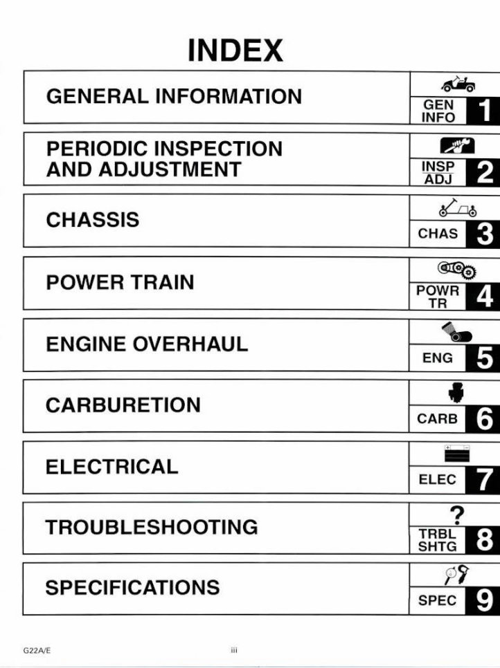
INDEX GENERAL INFORMATION l ~~~tu PERIODIC INSPECTION AND ADJUSTMENT CHASSIS I~ : C HAS II POWER TRAIN ENGINE OVERHAUL <t. ENG 1-1 CARBURETION f CARB I~ ELECTRICAL - ELE C ~~ TROUBLESHOOTING I ~ ~~?I:J SPECIFICATIONS G22NE iii
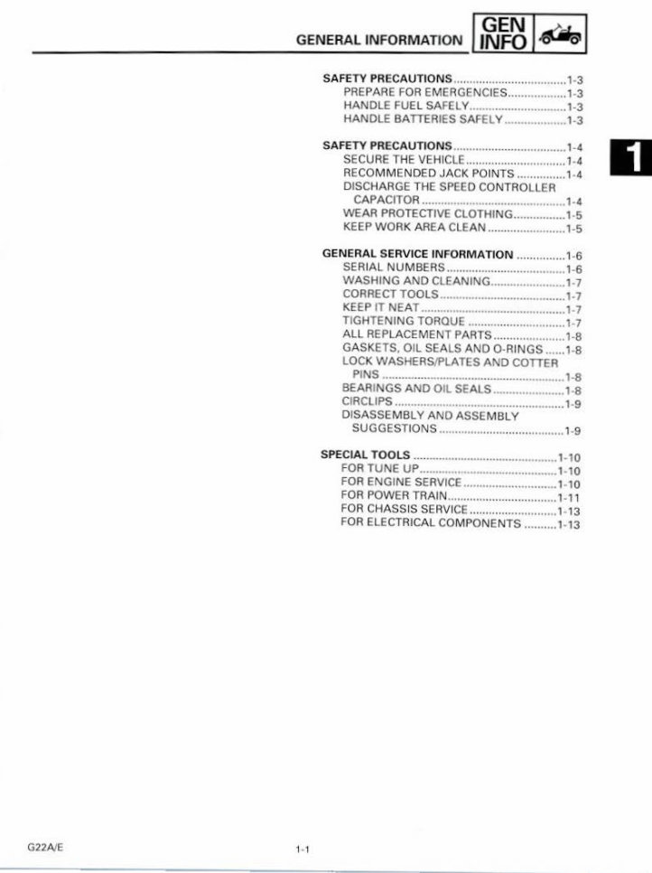
GENERAL INFO RMATION , ,~~~ I~ I SAFETY PR ECAUTIONS ......... .......................... 1-3 PREPARE FOR EM ERGENCIES ..................1-3 HANDLE FUEL SAFELY............................ 1-3 HANDLE BATTERIES SAFE LY .................. 1-3 SAFETY PRECAUTIONS ................................... l-4 SECU RE THE VEHICLE ................ .. ............. l- 4 RECOMMENDED JACK PO INTS ............... 1· 4 D DISCHARGE THE SPEED CONTROLLER CAPACITOR ............................................. 1-4 WEAR PROTECTIVE CLOTHING ................ 1· 5 KEEP WORK AREA CLEAN ........................ 1- 5 GENERAL SERVICE INFORMATION ............... 1·6 SER IAL NU M BE RS .. .... .......... .. ................... 1-6 WASHING AND CLEANING ....................... 1-7 CORRECT TOOLS ..................................... 1-7 KEEP IT NEAT ............................................. 1-7 TIGHTENING TO ROUE .............................. 1-7 ALL REPLACEMENT PARTS .... .................. 1-8 GA SKETS, OIL SEALS AND 0-RINGS .... .. 1· 8 LOCK WASHERS/PLATES AND COTTER PINS ................................................. .. ... 1-8 BEARINGS AND OIL SEALS ...................... 1·8 CIRCLIPS ..................................................... 1·9 DISASSE MBLY AND ASSEMBLY SUGGESTI ONS ....................................... 1-9 SPECIAL TOOLS ............................................. 1- 10 FOR TUNE UP ........................................... 1-1 0 FOR ENGINE SERVICE ............................. 1-10 FOR POWER TRA IN .................. .. ............ 1-11 FOR CHASSIS SERVICE .... .. .. ................... 1-13 FOR ELECTRICAL COM PONENTS .......... 1-13 G22NE
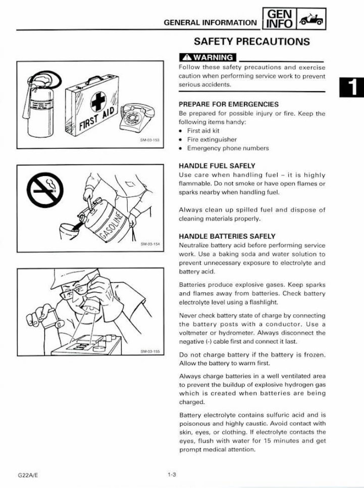
G22NE GENERAL INFORM ATION , ,~~~ I~ I SAFETY PRECAUTION S 1·3 A WARNING Fol low th ese safety precautions and exe r cise caution when performing service wor k to prevent serious accidents. PREPARE FOR EM ERGENCI ES Be prepared for possible injury or fire. Keep the f ollowing items handy: • First aid kit • Fire extinguisher • Emergency phone numbers HANDLE FUEL SAFELY Use care when handling fue l- it is hig hly flammable. Do not smoke or have open fl ames or sparks nearby when handling fuel. Always clean up spill ed fuel and dispose of cleaning materials properly. HANDLE BATTERIES SAFELY Neutralize battery acid before performing service work. Use a baki ng soda and water solution to prevent unnecessary exposure to electrolyte and battery acid. Batteries produce explosive gases. Keep sparks and flames away from batteries. Check battery electrolyte level usi ng a fl ashlight. Never check battery state of charge by connect ing the ba tt ery posts wi th a conductor . Use a voltmeter or hydrometer. Always disconnect the negative{ -) cable first and connect it last. Do not c harge battery if t he battery is frozen. Allow the battery to warm first. Always charge batteries in a well venti lated area to prevent the buildup of explosive hydrogen gas which is created wh en batteries are being charged. Battery electrolyte contains sulfuric acid and is poisonous and highly caustic. Avoid contact with skin, eyes, or clothing. If electrolyte contacts the eyes. flush with wa ter for 15 m i nutes and get prompt medical anent ion. D
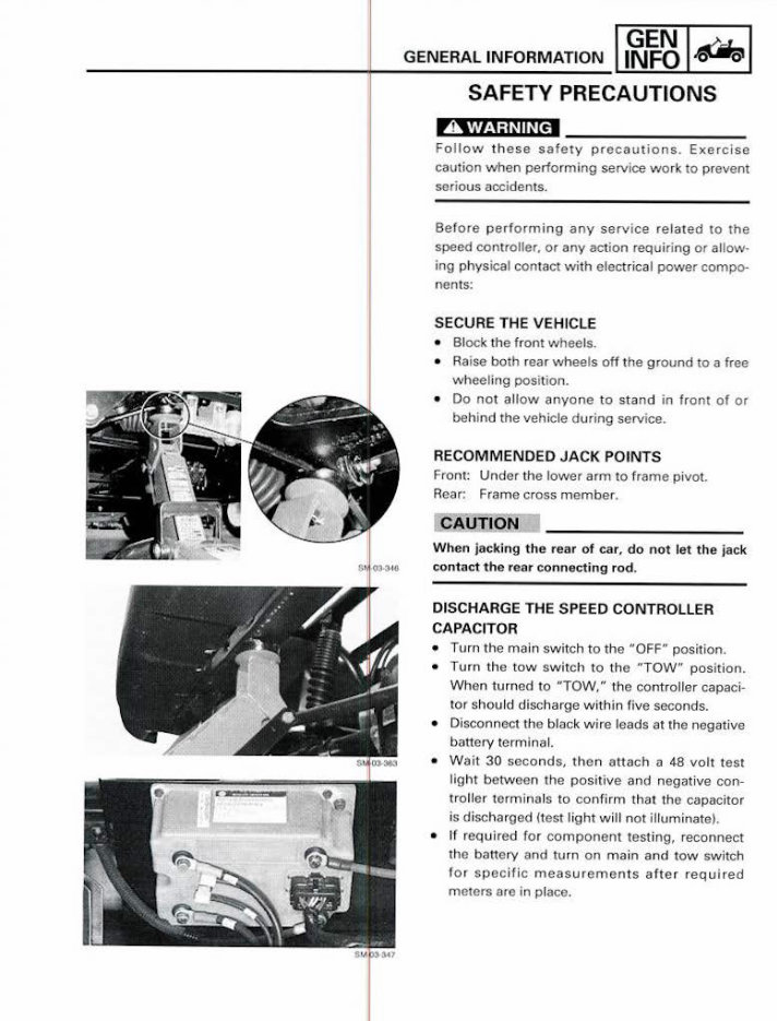
- -----+------IIGNEFON I -"'.eLl G ENERAL INFORM ATION . . ~. SAFETY PRECAUTIONS A WARNING Follow t hese safety precautions. Exercise caution when periorming service work to prevent serious accidents. Before perform in g any servi ce rel ated to the speed controller. or any act ion requiri ng or allow· ing physical contact with elect rical power compo- nent s: SECURE THE VEHICLE • Block the fr ont wheels. • Raise both rear wheels off the ground to a free wheeling position. • Do not allow anyone to stand in front of or behind the vehicle during service. RECOMM ENDED JACK POINTS Front: Under the lower arm to frame pivot. Rear: Frame cross member. When jacking the rear of car, do not let the jack contact the rear connecting rod. DISCHA RGE THE SPEED CONTROLLER CAPACITOR • Turn the main switch to the "OFF" position. • Turn the t ow switch to the "TOW" position. When turned to "TOW," the controller capaci- tor should discharge w ithin five seconds. • Disconnect the black wire leads at the negative battery termi nal. • Wait 30 seconds, then attach a 48 volt test light between the positive and negative con- troller t ermi nals to con firm that the capacitor is discharged (test light will not illuminate). • If requi red for component testing, reconnect the battery and turn on main and tow switch fo r specif ic measurements afte r r eq u ired meters are in p lace.
G22A/E GENERAL INFORMATION ,,~~~ I~ I SAFETY PRECAUTIONS 1· 5 WEAR PROTECT IVE CLOTHING Many permanent in juries could be prevented by w earing ap p ropr iate safety equipme nt during work. Whenever applicable, put on the fol lowi ng: • Safety glasses w ith side shi elds or gogg les when performing wor k like grinding, chiseling, sprayi ng or any other acti vity that could result in an object or chemical striking the ey e. • Ea rmuffs or earplugs when perfo rming loud work that could harm hearing. • Saf et y shoes when wo rking wit h heavy objects that could be dropped. • Respir atory protection when performing work i nvolving dust, vapor s, or gases that can cause respiratory problems. Avoi d weari ng loose clothi ng and jewel ry whi ch cou ld become caught in moving parts causing injury. KEEP WORK AREA CLEAN Properly ventil ate work ar ea 10 prev ent buildup of dangerous gases and keep the oxygen l evel above OSHA's 19.5 percent minimum level. K eep sh op fl oor cl ean and dry to pr event accidents d ue to slips. D
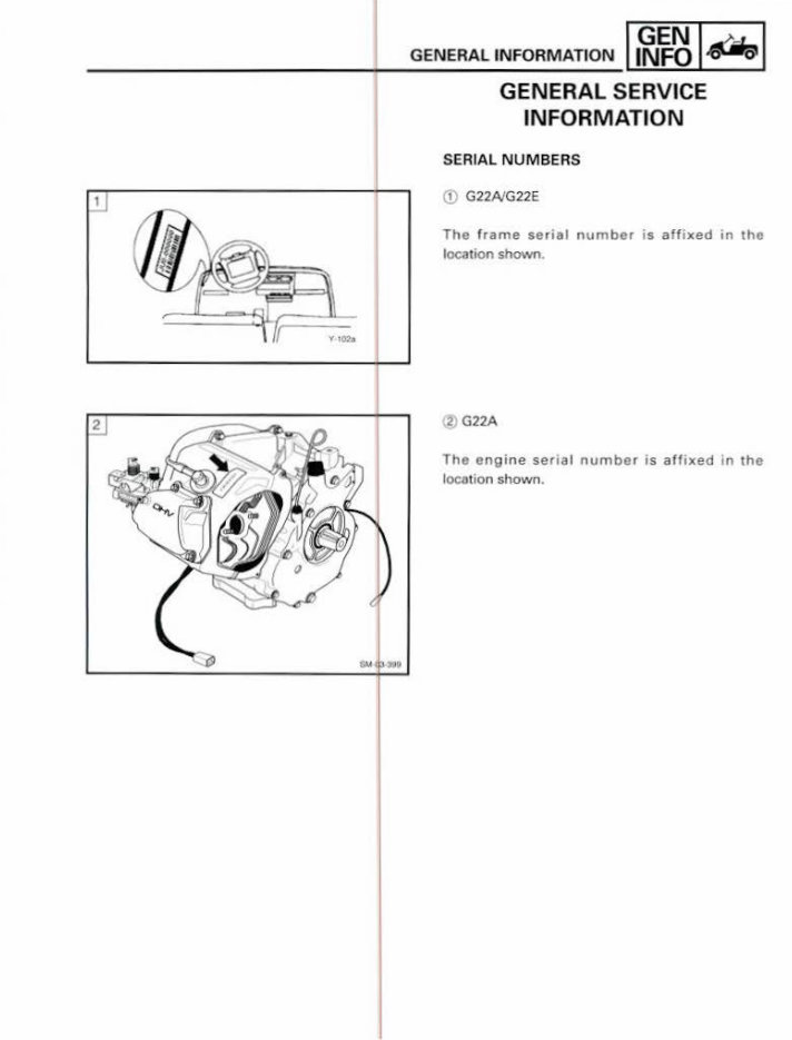
GENERAL INFORMATION I ~~~I~ I GENERAL SERVICE INFORMATION SER IAL NUMBERS 1 G22AIG22E The frame serial number is aff i xed in the location shown. 2 G22A Tho engine serial number is affixed in the location shown.
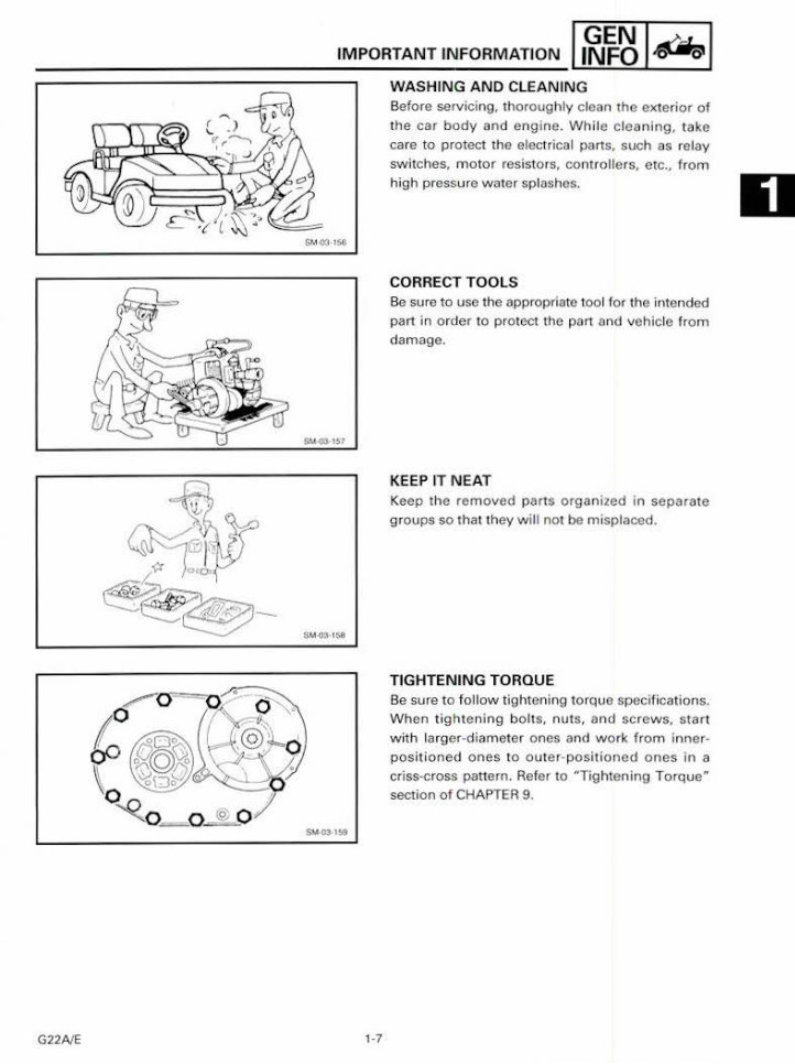
G22NE IMPORTANT INFORMATION ,,~~~ I~ I WASHING AND CLEANIN G $ MQ3 1 $6 1-7 Before servicing, thoroughly clean the exterior of t he car body and engine . Wh ile cleaning , take care to protect the electrical parts, such as relay switches, motor resistors, controllers, etc., from high pressure water splashes. CORRECT TOOLS Be sure to use the appropriate tool for the intended part in or< l er to protect the part and vehicle from damage. KEEP IT NEAT Keep the removed parts organ ized in separate groups so that they will not be misplaced. TIGHTENING TORQUE Be sure to follow tightening torque specifications. When ti ghtening bolts, nuts. and scr ews. start with larger-diameter ones and work from inner· posit i oned ones to outer - positioned ones in a criss-cross panern. Refer to "Tightening Torque" section of CHAPTER 9 . D
This is a comprehensive service manual for the YAMAHA G11, G14, G16, G19, and G20 ultima golf cart models. It contains over 500 pages of valuable information in Adobe PDF format, making it an essential resource for both professional mechanics and DIY enthusiasts.
The manual covers a wide range of topics, including general service information, periodic inspection and adjustment, chassis, power train, engine overhaul, carburetion, troubleshooting, electrical systems, and detailed specifications. It is the result of extensive editing work to ensure all content is deskewed, clear, and straight, providing hours of valuable guidance for maintaining and repairing these golf cart models.
Chapter 1: General Information
Frame Serial Number
Special Tools
Chapter 2: Periodic Inspection and Adjustment
Periodic Maintenance
Maintenance Chart
Inspection and Adjustment
Engine
Air Filter Cleaning
Carburetor Adjustment
Accelerator Stop Switch
Inspection/Accelerator Pedal Position Adjusting Bolt
Height Adjustment
Starter Belt Adjustment
Power Train
Primary Sheave Lubrication
Chapter 3: Chassis (Refer to G14A, G14E)
Chapter 4: Power Train for G16A
Primary Sheave
Removal
Disassembly
Inspection
Assembly
Installation
Secondary Sheave
Transmission
Differential Disassembly
Differential Inspection
Transmission Disassembly
Transmission Inspection
Transmission Assembly
Differential Assembly
Installation
Chapter 5: Engine Overhaul
Engine Removal
Preparation for Removal
Drive Belt
Primary Clutch
Air Cleaner Case
Carburetor
Wiring and Hose
Starter Generator
Muffler
Engine Oil Drain
Air Shroud
Flywheel
Cylinder Head
Crankcase Cover
Camshaft, Balancer Shaft, and Crankshaft
Piston and Connecting Rod
Oil Sender and Wire Guide Plate
Bearings Inspection and Repair
Cylinder Head
Valve and Valve Seat
Rocker Arm
Piston Ring and Pin
Crankshaft and Connecting Rod
Engine Assembly and Adjustment
Piston, Connecting Rod, and Crankcase Cover Bearings
Oil Sender and Wire Guide Plate
Piston and Connecting Rod
Crankshaft, Balancer Shaft, and Camshaft
Crankcase Cover
Flywheel
Cylinder Head and Rocker Arm
Cylinder Head
Ignition Unit
Air Shroud
Remounting Engine
Primary Sheave
Starter-Generator
Chapter 6: Carburetion
Chapter 7: Electrical
Wiring Diagram
Electrical Components
Ignition System
Troubleshooting
Chapter 8: Troubleshooting
Chapter 9: Specifications
General Specifications
Maintenance Specifications
Engine
Transmission
Electrical
Tightening Torque
Engine
Power Train
Cable/Wire Routing
Wiring Diagram
Whether you need to perform routine maintenance, troubleshoot electrical issues, or overhaul the engine, this manual provides detailed guidance and specifications to ensure the proper care and repair of your YAMAHA ultima golf cart. It is an indispensable resource for anyone working with these models.
Recently Viewed
5,521,897Happy Clients
2,594,462eManuals
1,120,453Trusted Sellers
15Years in Business
Price:
Actual Price:
Yamaha Electric Gas Golf Cart Car G11 G14 G16 G19 G20 Shop S