

Yamaha G14A / G14E Golf Cart Service & Repair Manual
What's Included?
Fast Download Speeds
Online & Offline Access
Access PDF Contents & Bookmarks
Full Search Facility
Print one or all pages of your manual
YAMAHA
ULTIMA GOLF CAR
SERVICE MANUAL
G14 AlE
G16 AlE
G19 E
G11 A
G20A

G14-A, G14-E
GOLF CAR SERVICE MANUAL
G14A,G14E
SERVICE MANUAL
1999 by Yamaha Motor Manufacturing
Corporation of America
3rd edition, June 1999
Printed in U.S.A.
P/N/ LIT-19616-00-00
(Rev. 8/96) (Rev. 6/99)

INTRODUCTION
This manual has been written by Yamaha Motor Manufacturing Corporation of America for use by
Authorized Yamaha dealers and their qualified mechanics. It is not possible to put an entire mechan-
ic's education into a manual, so it is assumed that persons using this book to perform maintenance
and repairs on Yamaha golf cars have a basic understanding of the mechanical concepts and proce-
dures inherent to these products. Without such knowledge, attempted repairs or service to this golf
car may render it unfit to use and/or unsafe.
Yamaha Motor Manufacturing Corporation of America is continually striving to further improve all
models manufactured by the company . Modifications are therefore inevitable and will, where applic-
able, appear in future editions of this manual.
TECHNICAL SERVICE DEPT
GOLF CAR SALES GROUP
YAMAHA MOTOR
MANUFACTURING CORP OF
AMERICA
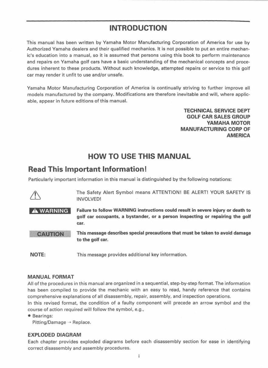
HOW TO USE THIS MANUAL
Read This Important Information!
Particularly important information in this manual is distinguished by the following notations:
A WARNING
The Safety Alert Symbol means ATTENTION! BE ALERT! YOUR SAFETY IS
INVOLVED!
Failure to follow WARNING instructions could result in severe injury or death to
golf car occupants, a bystander, or a person inspecting or repairing the golf
car.
Imij lf.IQRI Ij\j}jjj This message describes special precautions that must be taken to avoid damage
to the golf car.
NOTE: This message provides additional key information.
MANUAL FORMAT
All of the procedures in this manual are organized in a sequential, step-by-step format. The information
has been comp iled to provide the mechanic with an easy to read, handy reference that contains
comprehensive explanations of all disassembly, repair, assembly, and inspection operations.
In this revised format , the condition of a faulty component will precede an arrow symbol and the
course of action required will follow the symbol , e.g.,
• Bearings:
Pitting/Damage ___,. Replace.
EXPLODED DIAGRAM
Each chapter provides exploded diagrams before each disassembly section for ease in identifying
correct disassembly and assembly procedures.
CD ®
I~EF~IAI
I~JJI&I
® ®
lcHAsl~l
I~RI®I!01
@ @
I ENG l'-1
lcARBifl
<V ®
I ELEcl i1iii I
IJ~¥~1? I
®
lsPEcl P~l
@
~
®
~
@
~
@)
~
®
~
®
§
®)
[mJ
®
J..
a
@)
l
@
l
®
l
m m
Q
@) @ @
~ ~ ~
ii
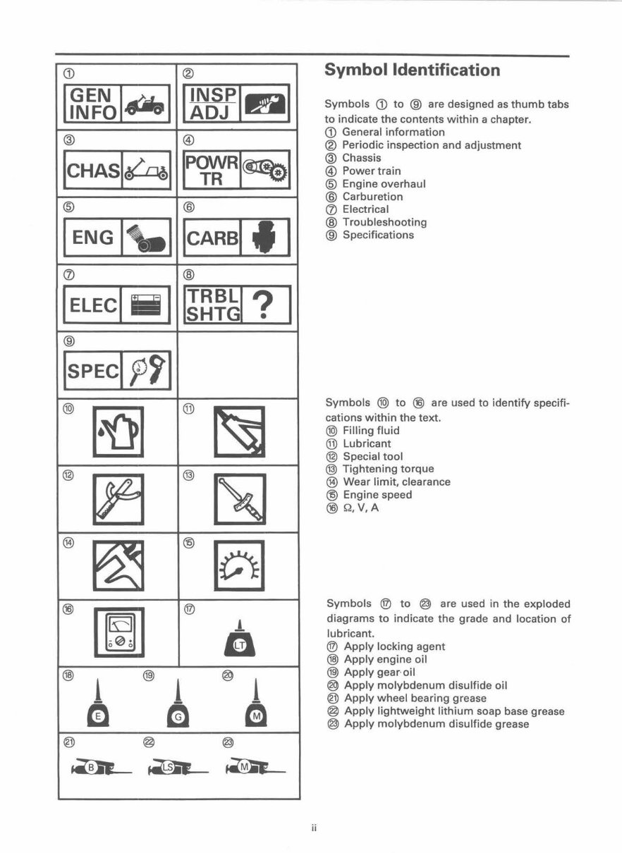
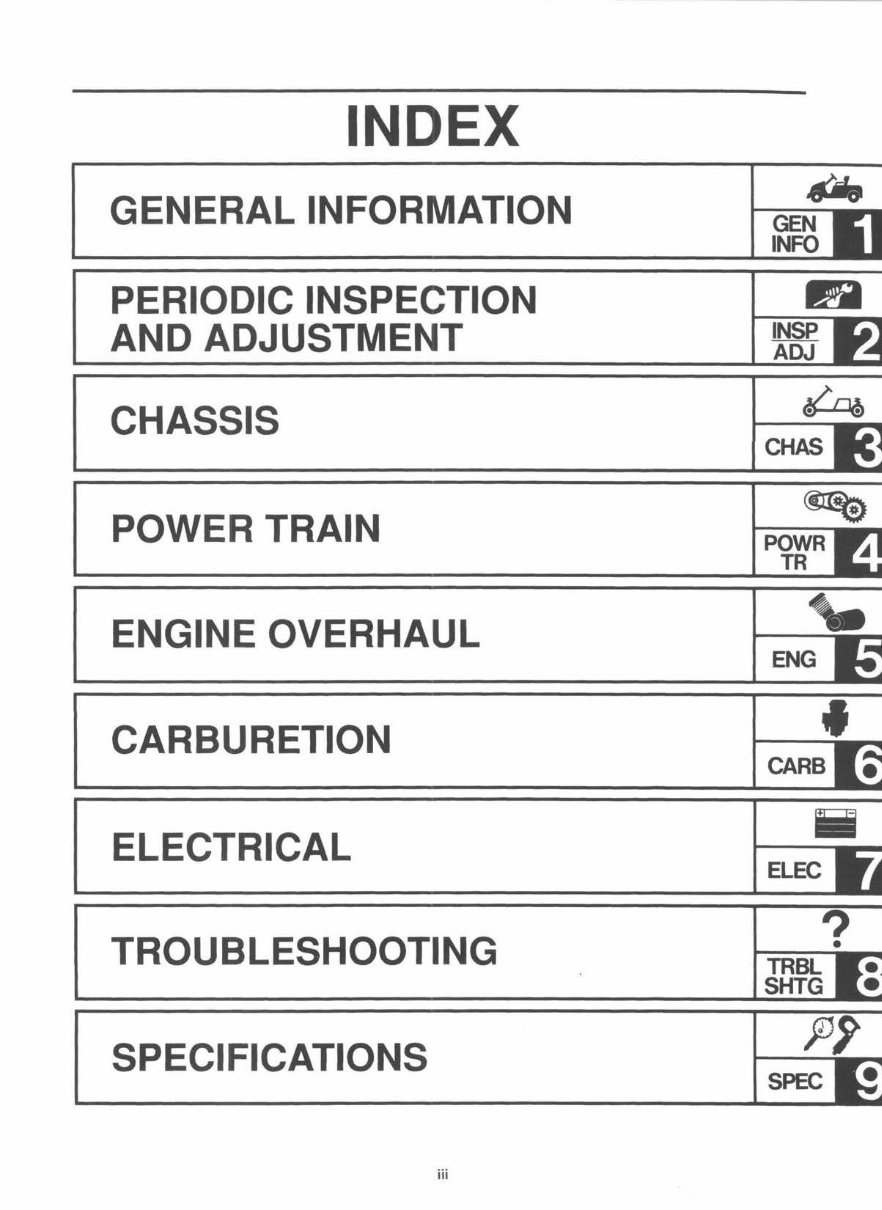
Symbol Identification
Symbols CD to ® are designed as thumb tabs
to indicate the contents within a chapter.
CD General information
® Periodic inspection and adjustment
@ Chassis
® Power train
@ Engine overhaul
@ Carburetion
<V Electrical
® Troubleshooting
® Specifications
Symbols @ to ®) are used to identify specifi-
cations within the text.
@ Filling fluid
® Lubricant
@ Special tool
@) Tightening torque
® Wear limit, clearance
@ Engine speed
®) Q,V,A
Symbols ® to @ are used in the exploded
diagrams to indicate the grade and location of
lubricant.
® Apply locking agent
@) Apply engine oil
@ Apply gear·oil
® Apply molybdenum disulfide oil
@) Apply wheel bearing grease
@ Apply lightweight lithium soap base grease
@ Apply molybdenum disulfide grease
CARBURETION
CARB
ELECTRICAL
Iii
ELEC
TROUBLESHOOTING
?
•
TRBL
SHTG
SPECIFICATIONS
SPEC
iii

CHAPTER 1
GENERAL INFORMATION
SAFETY PRECAUTIONS ................................... 1-1
GENERAL SERVICE INFORMATION ............... 1-3
FRAME SERIAL NUMBER .......................... 1-3
WASHING AND CLEANING ...................... 1-4
THE RIGHT TOOLS ................................... 1-4
KEEP IT NEAT ............................................. 1-4
TIGHTENING TORQUE .............................. 1-4
ALL REPLACEMENT PARTS ...................... 1-5
GASKETS, OIL SEALS AND O-RINGS ...... 1-5
LOCK WASHERS/PLATES AND
COTTER PINS .......................................... 1-5
BEARINGS AND OIL SEALS ...................... 1-5
CIRCLIPS ..................................................... 1-6
DISASSEMBLY AND ASSEMBLY
SUGGESTIONS ....................................... 1-6
SPECIAL TOOLS ............................................... 1-7
FOR TUNE UP ............................................. 1-7
FOR ENGINE SERVICE ............................... 1-7
FOR POWER TRAIN ................................... 1-8
FOR CHASSIS SERVICE ............................. 1-9
FOR ELECTRICAL COMPONENTS .......... 1-10
(Rev. 6/99)

You're Reading a Preview
What's Included?
Fast Download Speeds
Online & Offline Access
Access PDF Contents & Bookmarks
Full Search Facility
Print one or all pages of your manual
$41.99
Viewed 12 Times Today


Secure transaction
What's Included?
Fast Download Speeds
Online & Offline Access
Access PDF Contents & Bookmarks
Full Search Facility
Print one or all pages of your manual
$41.99
Find comprehensive service and repair manuals for the Yamaha G14A and G14E golf carts. These manuals cover a range of models, including:
- G11 A
- G14 A/E
- G16 A/E
- G19 E
- G20 A


