

1983-1989 Yamaha G1 Golf Cart Service & Repair Manual
What's Included?
Fast Download Speeds
Online & Offline Access
Access PDF Contents & Bookmarks
Full Search Facility
Print one or all pages of your manual
YAMAHA
SERVICE MANUAL
@YAMAHA
GOLF CAR
GI-AM3
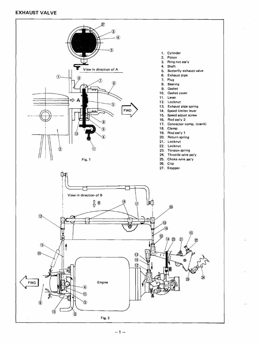
EXHAUST VALVE
Fig. 1
1. Cylinder
2. Piston
3. Ring nut ass'y
4. Shaft
View in direct~o of A
5. Butterfly exhaust valve
6. Exhaust plpe
7. Plug
8. Bear~n
9. Gasket
10. Gasket cover
11. Lever
12. Locknut
13. Exhaust pipe spring
14. Speed limiter lever
15. Speed adjust screw
16. Rod ass'y 2
17. Connector comp. (crank)
18. Clamp
19. Rod ass'y 1
20. Return spring
21. Locknut
22. Locknut
23. Torsion spring
24. Throttle wire ass'y
25. Choke wire ass'y
26. Cl~
27. Stopper
Fig. 2
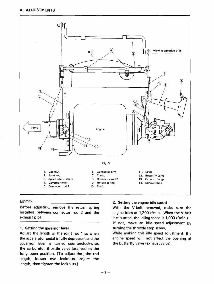
A. ADJUSTMENTS
View in direction of B
Fig. 3
1. Locknut 6. Connector arm 11. Lever
2. Joint rod 7. Clamp 12. Butterfly valve
3. Speed adjust screw 8. Connector rod 2 13. Exhaust flange
4. Governor lever 9. Return spring 14. Exhaust pipe
5. Connecter rod 1 10. Shaft
NOTE:
Before adjusting,
installed between
remove the return spring
connector rod 2 and the
exhaust pipe.
1. Setting the governor lever
Adjust the length of the joint rod 1 so when
the accelerator pedal is fully depressed, and the
governor lwer is turned counterclockwise,
the carburetor thorttle valve just reaches the
fully open position. (To adjust the joint rod
length, loosen two locknuts, adjust the
length, then tighten the locknuts.)
2. Setting the engine idle speed
With the V-belt removed, make sure the
engine idles at 1,200 rlmin. (When the V-belt
is mounted, the idling speed is 1,000 rlmin.)
If not, make an idle speed adjustment by
turning the throttle stop screw.
While making this idle speed adjustment, the
engine speed will not affect the opening of
the butterfly valve (exhaust valve).
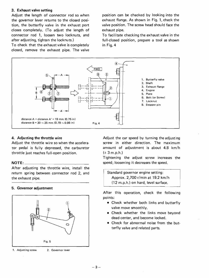
3. Exhaust valve setting
Adjust the length of connector rod so when
the governor lever returns t o the closed posi-
tion, the butterfly valve in the exhaust port
closes completely. (To adjust the length of
connector rod 1, loosen two locknuts, and
after adjusting, tighten the locknuts.)
To check that the exhaust valve is completely
closed, remove the exhaust pipe. The valve
position can be checked by looking into the
exhaust flange. As shown in Fig. 1, check the
valve position. The screw head should face the
exhaust pipe.
To facilitate checking the exhaust valve in the
full-closed position, prepare a tool as shown
in Fig. 4
1. Butterfly valve
2. Shaft
3. Exhaust flange
4. Engine
5. Plate
6. Bolt (or Screw)
7. Locknut
8. Stopper pin
distance A = distance A ' = 19 mm (0.75 in)
distance B = 20 - 25 mm (0.79 -0.98 in)
4. Adjusting the throttle wire
Adjust the throttle wire so when the accelera-
tor pedal is fully depressed, the carburetor
throttle just reaches fu II-open position.
NOTE:
After adjusting the throttle wire, install the
return spring between connector rod 2, and
the exhaust pipe.
5. Governor adjustment
Fig. 5
Adjust the car speed by turning the adjusting
screw in either direction. The maximum
amount of adjustment is about 4.8 kmlh
(* 3 m.p.h.1
Tightening the adjust screw increases the
speed; loosening it decreases the speed.
Approx. 2,700 r/min at 19.2 kmlh
(12 m.p.h.) on hard, level surface.
After this operation, check the following
points:
Check whether both links and butterfly
valve move smoothly.
Check whether the links move beyond
dead center, and become locked.
Check for abnormal noise from the but-
terfly valve and related parts.
1. Adjusting screw 2. Governor lever
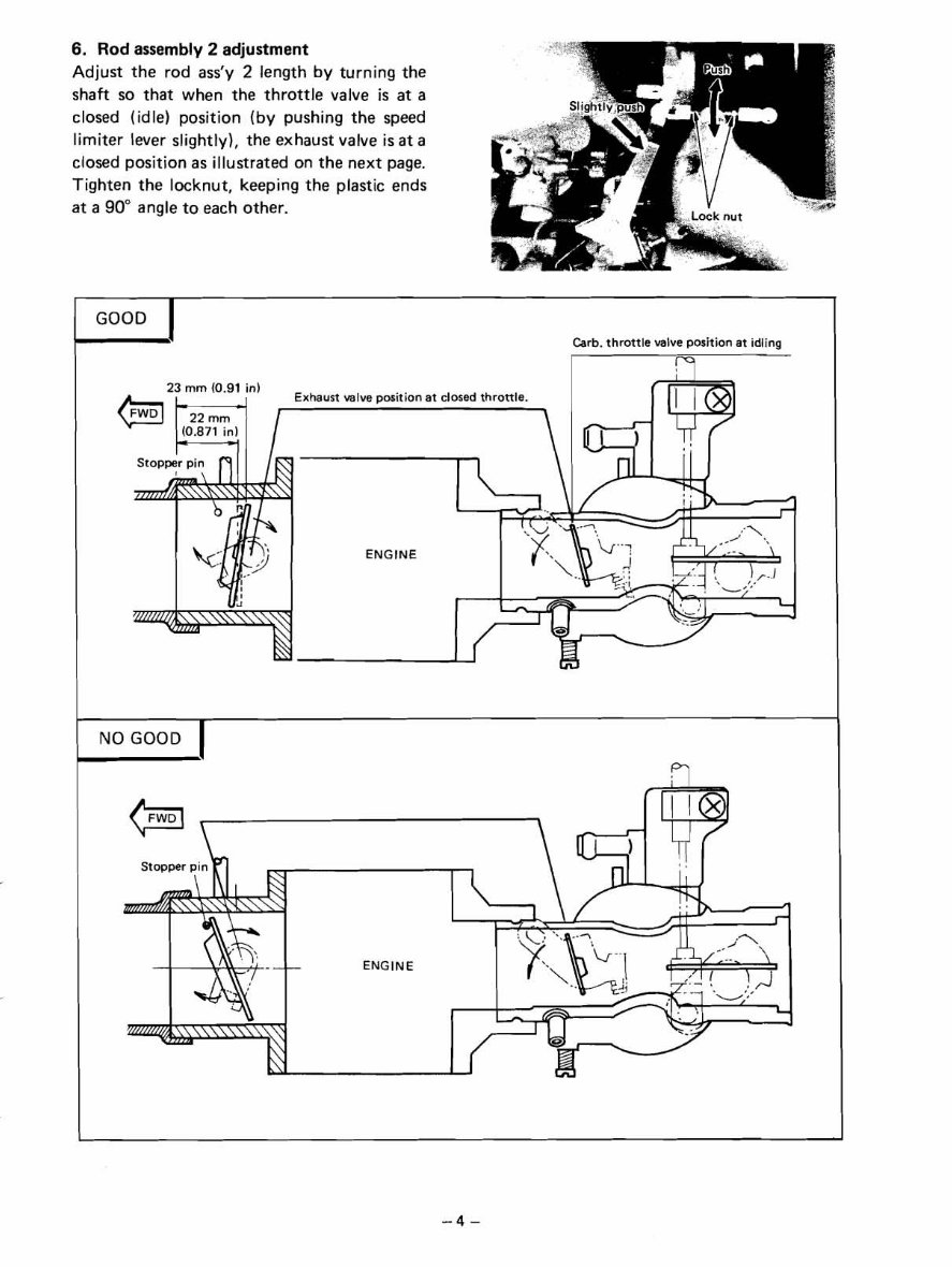
6. Rod assembly 2 adjustment
Adjust the rod ass'y 2 length by turning the
shaft so that when the throttle valve is at a
closed (idle) position (by pushing the speed
limiter lever slightly), the exhaust valve is at a
closed position as illustrated on the next page.
Tighten the locknut, keeping the plastic ends
at a 90" angle to each other.
GOOD
Carb. throttle valve position at idling
ENGINE
NOTE:
Check t o see that when the throttle valve is
fully open, the exhaust valve is also fully
open.
B. DISASSEMBLY AND ASSEMBLY
In general, except when links are damaged or
the joint is extremely worn, neither removal
nor disassembly is necessary. When dismoun-
ting the engine from the chassis or reassembl-
ing links after replacing parts, the adjustments
specified in D, above must be performed.
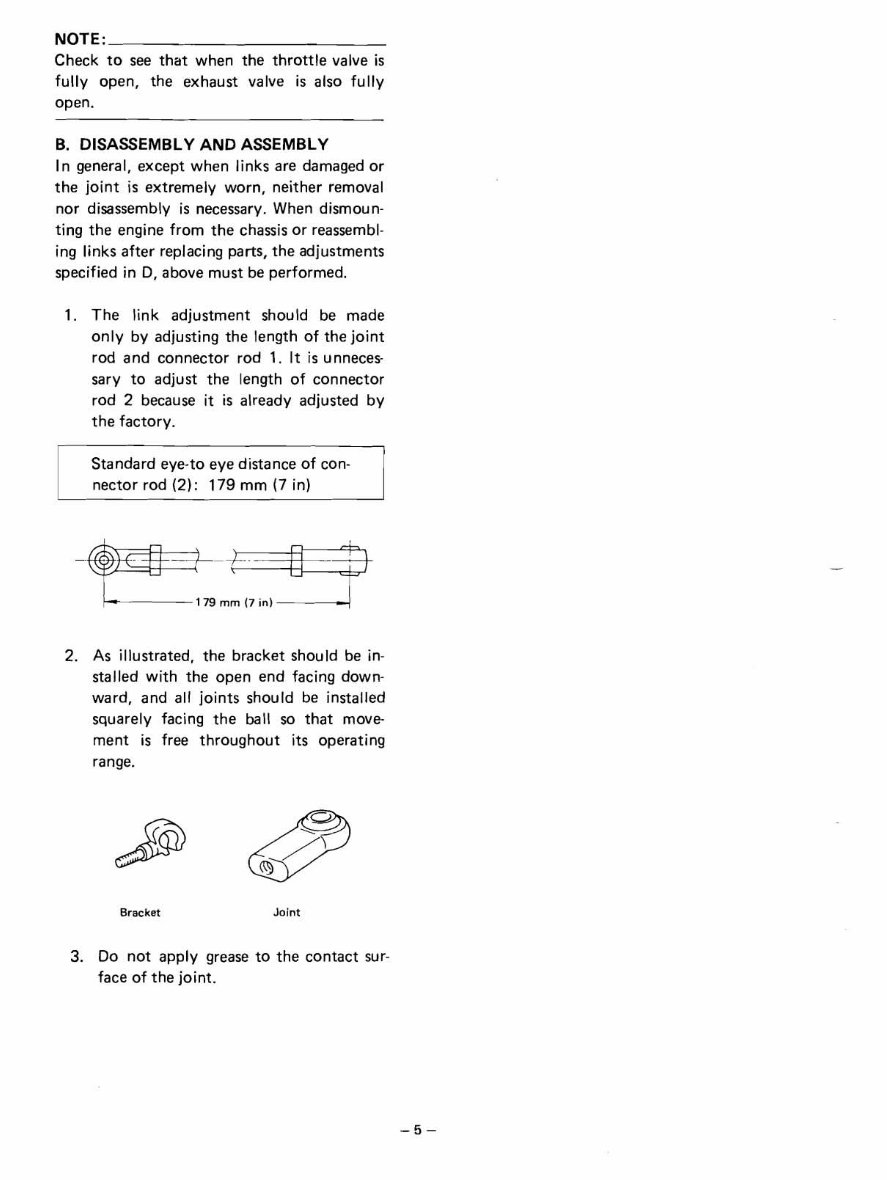
1. The link adjustment should be made
only by adjusting the length of the joint
rod and connector rod 1. It is unneces-
sary to adjust the length of connector
rod 2 because it is already adjusted by
the factory.
Standard eye-to eye distance of con-
nector rod (2): 179 mm (7 in)
2. As illustrated, the bracket should be in-
stalled with the open end facing down-
ward, and all joints should be installed
squarely facing the ball so that move-
ment is free throughout its operating
range.
Bracket Joint
3. Do not apply grease to the contact sur-
face of the joint.
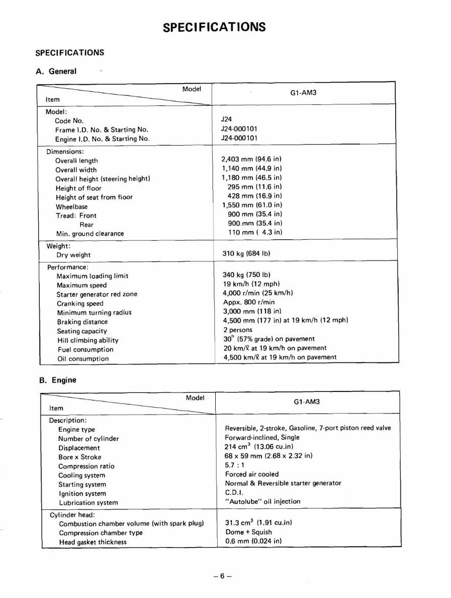
SPECI FICATIONS
A. General
Weight:
Dry weight
Model
GI -AM3
Item
Performance:
Maximum loading limit
Maximum speed
Starter generator red zone
Cranking speed
Minimum turning radius
Braking distance
Seating capacity
Hill climbing ability
Fuel consumption
Oil consumption
Model:
Code No.
Frame I.D. No. & Starting NO.
Engine I.D. No. & Starting No.
Dimensions:
Overall length
Overall width
Overall height (steering height)
Height of floor
Height of seat from floor
Wheelbase
Tread: Front
Rear
340 kg (750 Ib)
19 kmlh (12 mph)
4,000 rlmin (25 kmlh)
Appx. 800 rlmin
3,000 mm (118 in)
4,500 mm (177 in) at 19 kmlh (12 mph)
2 persons
30" (57%grade) on pavement
20 kmlP at 19 km/h on pavement
4,500 km/P at 19 kmlh on pavement
J24
J24-000101
J24-000 101
2,403 mm (94.6 in)
1,140 mm (44.9 in)
1,180 mm (46.5 in)
295 mm (11.6 in)
428 mm (16.9 in)
1,550 mm (61.0 in)
900 mm (35.4 in)
900.mm (35.4 in)
6. Engine
Min. ground clearance 1 110 mm ( 4.3 in)
-
Model
-
.
Description:
Engine type
Number of cylinder
Displacement
Bore x Stroke
Compression ratio
Cooling system
Starting system
Ignition system
Lubrication system
Cylinder head:
Combustion chamber volume (with spark plug)
Compression chamber type
Head gasket thickness
G1 -AM3
Reversible, 2-stroke, Gasoline, 7-port piston reed valve
Forward-inclined, Single
214 cm3 (13.06 cu.in)
68 x 59 mm (2.68 x 2.32 in)
5.7 : 1
Forced air cooled
Normal & Reversible starter generator
C.D.I.
"Autolube" oil injection
31.3 cm3 (1.91 cu.in)
Dome + Squish
0.6 mm (0.024 in)
Material
Bore size
Taper limit
Out of round limit
Model
Item
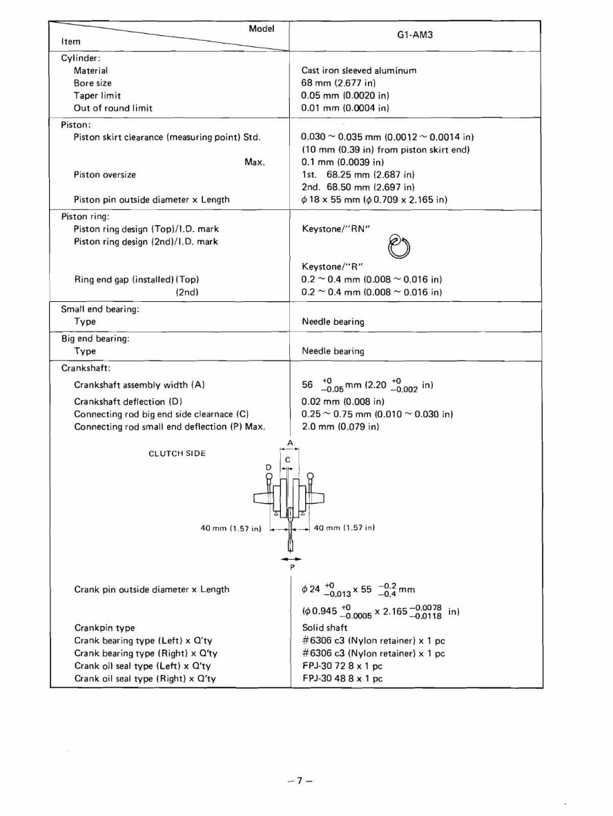
Cylinder:
Cast iron sleeved aluminum
68 mm (2.677 in)
0.05 mm (0.0020 in)
0.01 mm (0.0004 in)
GI-AM3
Piston:
Piston skirt clearance (measuringpoint) Std.
Max.
Piston oversize
Piston pin outside diameter x Length
Piston ring:
Piston ring design (Top)/l.D. mark
Piston ring design (2nd)ll.D. mark
Ring end gap (installed)(Top)
(2nd)
0.030 - 0.035 mm (0.0012 - 0.0014 in)
(10 mm (0.39 in) from piston skirt end)
0.1 mm (0.0039 in)
1st. 68.25 mm (2.687 in)
2nd. 68.50 mm (2.697 in)
418x 55 mm (40.709 x 2.165in)
Kevstonel" RN"
Keystone1"R"
0.2 - 0.4 rnrn (0.008 - 0.016 in)
0.2 - 0.4 mm (0.008 - 0.016 in)
I Type I Needle bearing
Small end bearing:
Big end bearing:
Crankshaft: I
Needle bearing
Crankshaft assembly width (A)
Crankshaft deflection (0
Connecting rod big end side clearnace (C)
Connecting rod small end deflection (P Max.
CLUTCH SIDE
40 rnrn
+O
56 TE.05mm (2.20 -0.002 in)
0.02 mm (0.008 in)
0.25- 0.75 rnm (0.010 - 0.030 in)
2.0 mm (0.079 in)
Crank pin outside diameter x Length
(1.57 in)
x 2.1652: in)
1 00'945-0.0005
Crankpin type
Crank bearing type (Left) x Q'ty
Crank bearing type (Right) x Q'ty
Crank oil seal type (Left) x Q'ty
Crank oil seal type (Right) x Q'ty
Solid shaft
#6306 c3 (Nylon retainer) x 1 pc
#6306 c3 (Nylon retainer) x 1 pc
FPJSO 72 8 x 1 PC
FPJ-30 48 8 x 1 PC
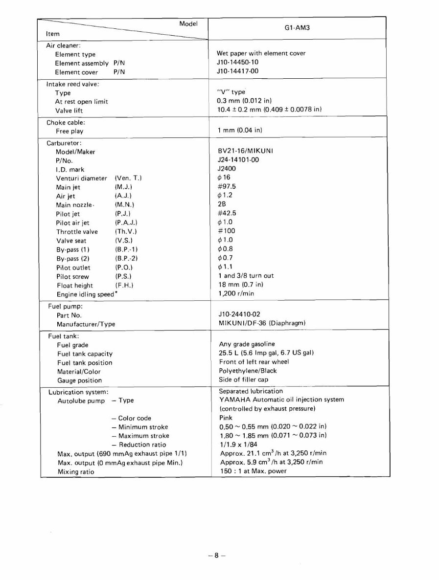
Air cleaner:
Model
-
Element type
Element assembly PIN
Element cover PIN
Intake reed valve:
GI -AM3
Type
At rest open limit
Valve lift
Choke cable:
Free play
Carburetor:
ModelIMaker
PINO
I.D. mark
Venturi diameter (Ven. T.)
Main jet (M.J.)
Air jet (A.J.)
Main nozzle. (M.N.)
Pilot jet (P.J.)
Pilot air jet (P.A.J.)
Throttle valve (Th.V.)
Valve seat (V.S.)
By-pass (1 ) (B.P.-1
By-pass (2) (B.P.-2)
Pilot outlet (P.O.)
Pilot screw (P.S.)
Float height (F.H.)
Engine idling speed"
Fuel pump:
Part No.
ManufacturerIType
Fuel tank:
Fuel grade
Fuel tank capacity
Fuel tank position
MaterialIColor
Gauge position 1
Lubrication system:
Autolube pump - Type
- Color code
- Minimum stroke
- Maximum stroke
- Reduction ratio
Max. output (690 mmAg exhaust pipe 111)
Max. output (0 mmAg exhaust pipe Min.)
Mixing ratio
Wet paper with element cover
J10-14450-10
J10-14417-00
"V" type
0.3 mm (0.012 in)
10.4 f 0.2 mm (0.409 f 0.0078 in)
1 mm (0.04 in)
BV21-161MIKUN
J24-14101-00
J2400
4 16
#97.5
41.2
2B
#42.5
4 1 .o
# 100
41.0
4 0.8
$0.7
41.1
1 and 318 turn out
18 mm (0.7 in)
1,200 rlmin
J10-24410-02
MIKUNIIDF-36 (Diaphragm)
Any grade gasoline
25.5 L (5.6 Imp gal, 6.7 US gal)
Front of left rear wheel
PolyethyleneIBlack
Side of filler cap
Separated lubrication
YAMAHA Automatic oil injection system
(controlled by exhaust pressure)
Pink
0.50 - 0.55 mm (0.020 - 0.022 in)
1.80 - 1.85 mm (0.071 - 0.073 in)
111.9 x 1/84
Approx. 21 . cm3/h at 3,250 rlmin
Approx. 5.9 cm3/h at 3,250 r/min
150 : 1 at Max. Dower
You're Reading a Preview
What's Included?
Fast Download Speeds
Online & Offline Access
Access PDF Contents & Bookmarks
Full Search Facility
Print one or all pages of your manual
$33.99
Viewed 73 Times Today


Secure transaction
What's Included?
Fast Download Speeds
Online & Offline Access
Access PDF Contents & Bookmarks
Full Search Facility
Print one or all pages of your manual
$33.99
Get the Yamaha G1 Golf Cart 1983-1989 Service Repair Manual for comprehensive factory service and owners manual. This manual provides fast access to essential technical information, allowing you to work on your golf cart yourself and save money. It is compatible with all Windows and Mac operating systems. Securely purchase using PayPal or credit card.


