

EZ GO RXV GOLF CART Service Parts Manual
What's Included?
Fast Download Speeds
Online & Offline Access
Access PDF Contents & Bookmarks
Full Search Facility
Print one or all pages of your manual
RXV GASOLINE
SERVICE PARTS MANUAL
ISSUED JANUARY 2008 REVISED JULY 2008
607976


Page i Service Parts Manual
SERVICE PARTS MANUAL
GASOLINE POWERED
GOLF CARS & PERSONAL VEHICLES
RXV GOLF CAR
RXV FREEDOM™
RXV SHUTTLE 2 + 2
Starting Model Year 2008
E-Z-GO Division of TEXTRON, Inc. reserves the right to incorporate engineering and design changes to products in this Manual, without obligation to
include these changes on units leased/sold previously.
The information contained in this Manual may be revised periodically by the E-Z-GO Division, and therefore is subject to change without notice.
The E-Z-GO Division DISCLAIMS LIABILITY FOR ERRORS IN THIS MANUAL, and the E-Z-GO Division SPECIFICALLY DISCLAIMS LIABILITY FOR
INCIDENTAL AND CONSEQUENTIAL DAMAGES resulting from the use of the information and materials in this Manual.
TO CONTACT US
NORTH AMERICA:
TECHNICAL ASSISTANCE & WARRANTY PHONE: 1-800-774-3946, FAX: 1-800-448-8124
SERVICE PARTS PHONE: 1-888-GET-EZGO (1-888-438-3946), FAX: 1-800-752-6175
INTERNATIONAL: PHONE: 001-706-798-4311, FAX: 001-706-771-4609
E-Z-GO DIVISION OF TEXTRON, INC., 1451 MARVIN GRIFFIN ROAD, AUGUSTA, GEORGIA USA 30906-3852

Page ii Service Parts Manual
GENERAL INFORMATION
This vehicle has been designed and manufactured in the United States of America (USA) as
a ‘World Vehicle’. The Standards and Specifications listed in the following text originate in
the USA unless otherwise indicated.
The use of non Original Equipment Manufacturer (OEM) approved parts may void the
warranty.
Tampering with or adjusting the governor to permit vehicle to operate at above factory
specifications will void the vehicle warranty.
When servicing engines, all adjustments and replacement components must be per original
vehicle specifications in order to maintain the United States of America Federal and State
emission certification applicable at the time of manufacture.
BATTERY PROLONGED STORAGE
All batteries will self discharge over time. The rate of self discharge varies depending on the
ambient temperature and the age and condition of the batteries.
A fully charged battery will not freeze in winter temperatures unless the temperature falls
below -75° F (-60° C).

Page iii Service Parts Manual
SECTION Page No.
TABLE OF CONTENTS
HOW TO USE THE SERVICE PARTS MANUAL . . . . . . . . . . . . . . . . . . . . . . . . . . . . . . . . . . . . . . . . . . . . . Vii
ACCELERATOR PEDAL ASSEMBLY . . . . . . . . . . . . . . . . . . . . . . . . . . . . . . . . . . . . . . . . . . . . . . . . . . . . . A-1
• Pedal Cover
• Accelerator Pedal
• Accelerator Pedal Switch
AIR FILTER . . . . . . . . . . . . . . . . . . . . . . . . . . . . . . . . . . . . . . . . . . . . . . . . . . . . . . . . . . . . . . . . . . . . . . . . . . B-1
• Air Cleaner Element
• Air Filter Housing
• Air Cleaner Hose
BODY - FRONT . . . . . . . . . . . . . . . . . . . . . . . . . . . . . . . . . . . . . . . . . . . . . . . . . . . . . . . . . . . . . . . . . . . . . . . C-1
• Front Bumper
• Front Splash Shield
• Cowl
• Nameplate
• Instrument Panel
• Instrument Panel Trim
• Cup Holder
BODY - MID SECTION . . . . . . . . . . . . . . . . . . . . . . . . . . . . . . . . . . . . . . . . . . . . . . . . . . . . . . . . . . . . . . . . . C-5
• Pedal Cover
• Floorboard
• Floormat
• Rocker Panels
BODY - REAR . . . . . . . . . . . . . . . . . . . . . . . . . . . . . . . . . . . . . . . . . . . . . . . . . . . . . . . . . . . . . . . . . . . . . . . . C-7
• Rear Body
• Rear Splash Shields
• Seat Support
• Bagwell Liner
• Access Panel
BODY - ACCESSORIES . . . . . . . . . . . . . . . . . . . . . . . . . . . . . . . . . . . . . . . . . . . . . . . . . . . . . . . . . . . . . . . C-11
• Sand Bottle
• Cooler Jug
• Scuff Guard
• Soft Swipe
BODY - ACCESSORIES . . . . . . . . . . . . . . . . . . . . . . . . . . . . . . . . . . . . . . . . . . . . . . . . . . . . . . . . . . . . . . . C-13
• Divot Repair Kit
• Club & Ball Washer
BRAKES . . . . . . . . . . . . . . . . . . . . . . . . . . . . . . . . . . . . . . . . . . . . . . . . . . . . . . . . . . . . . . . . . . . . . . . . . . . . D-1
• Brake Pedal Pad
• Brake Pedal
• Brake Cable
• Brake Drum Assembly
CARBURETOR AND CHOKE. . . . . . . . . . . . . . . . . . . . . . . . . . . . . . . . . . . . . . . . . . . . . . . . . . . . . . . . . . . . E-1
• Carburetor
• Main Jet
• Choke Cable
CLUTCH . . . . . . . . . . . . . . . . . . . . . . . . . . . . . . . . . . . . . . . . . . . . . . . . . . . . . . . . . . . . . . . . . . . . . . . . . . . . F-1
• Drive Clutch
• Driven Clutch

Page iv
SECTION Page No.
TABLE OF CONTENTS
DIRECTION SELECTOR. . . . . . . . . . . . . . . . . . . . . . . . . . . . . . . . . . . . . . . . . . . . . . . . . . . . . . . . . . . . . . . . G-1
• Push/Pull Shifter Cable
• Compression Spring
• Neutral Lock Bracket
ELECTRICAL SYSTEM . . . . . . . . . . . . . . . . . . . . . . . . . . . . . . . . . . . . . . . . . . . . . . . . . . . . . . . . . . . . . . . . H-1
• Main Harness
• Battery
• Hour Meter
• Ground Cable
• Turn Signal
• Headlight
• Key Switch
• Tail Lights
ENGINE AND MUFFLER . . . . . . . . . . . . . . . . . . . . . . . . . . . . . . . . . . . . . . . . . . . . . . . . . . . . . . . . . . . . . . . J-1
• Engine
• Muffler
• Oil Dip Stick
• Oil Filter
ENGINE MOUNTING. . . . . . . . . . . . . . . . . . . . . . . . . . . . . . . . . . . . . . . . . . . . . . . . . . . . . . . . . . . . . . . . . . . K-5
• Engine Pan Mount
• Front Engine Mount
FRONT SUSPENSION AND STEERING . . . . . . . . . . . . . . . . . . . . . . . . . . . . . . . . . . . . . . . . . . . . . . . . . . . L-1
• Strut
• Spindle
• A-Arm
• Steering Box
• Steering Column
• Steering Wheel
FUEL SYSTEM . . . . . . . . . . . . . . . . . . . . . . . . . . . . . . . . . . . . . . . . . . . . . . . . . . . . . . . . . . . . . . . . . . . . . . M-1
• Fuel Tank
• Pulse Line
REAR AXLE . . . . . . . . . . . . . . . . . . . . . . . . . . . . . . . . . . . . . . . . . . . . . . . . . . . . . . . . . . . . . . . . . . . . . . . . . N-1
• Axle Shaft
• Axle Tube
• Oil Check Plug
REAR SUSPENSION . . . . . . . . . . . . . . . . . . . . . . . . . . . . . . . . . . . . . . . . . . . . . . . . . . . . . . . . . . . . . . . . . . P-1
• Shocks
• Leaf Spring
• Shackles
SEATING - GOLF CAR . . . . . . . . . . . . . . . . . . . . . . . . . . . . . . . . . . . . . . . . . . . . . . . . . . . . . . . . . . . . . . . . . Q-1
• Seat Bottom
• Seat Back
• Hip Restraints
• Seat Back Support
SEATING - SHUTTLE 2+2 . . . . . . . . . . . . . . . . . . . . . . . . . . . . . . . . . . . . . . . . . . . . . . . . . . . . . . . . . . . . . . Q-5
• Seat Bottom, Rear Facing Seat
• Seat Back, Rear Facing Seat
• Floorboard, Rear Facing Seat
• Arm Rest, Rear Facing Seat

Page v
SECTION Page No.
TABLE OF CONTENTS
STARTER / GENERATOR . . . . . . . . . . . . . . . . . . . . . . . . . . . . . . . . . . . . . . . . . . . . . . . . . . . . . . . . . . . . . . R-5
• Starter
• Starter Belt
• Starter Tensioner
TOW BAR . . . . . . . . . . . . . . . . . . . . . . . . . . . . . . . . . . . . . . . . . . . . . . . . . . . . . . . . . . . . . . . . . . . . . . . . . . . S-1
WEATHER PROTECTION - GOLF CAR . . . . . . . . . . . . . . . . . . . . . . . . . . . . . . . . . . . . . . . . . . . . . . . . . . . T-1
• Sun Top
WEATHER PROTECTION - SHUTTLE 2+2 . . . . . . . . . . . . . . . . . . . . . . . . . . . . . . . . . . . . . . . . . . . . . . . . . T-3
• Sun Top
WEATHER PROTECTION - WINDHIELD. . . . . . . . . . . . . . . . . . . . . . . . . . . . . . . . . . . . . . . . . . . . . . . . . . . T-5
WHEELS AND TIRES . . . . . . . . . . . . . . . . . . . . . . . . . . . . . . . . . . . . . . . . . . . . . . . . . . . . . . . . . . . . . . . . . . U-1
• Tire & Wheel Assembly
• Lug Nuts
• Dust Cap

Page vi
SECTION Page No.
TABLE OF CONTENTS
Page vii Service Parts Manual
This manual is divided into several sections:
GENERAL INFORMATION
• TABLE OF CONTENTS
• HOW TO USE THE SERVICE PARTS MANUAL
ILLUSTRATED PARTS BREAKDOWN
• Contains illustrations and parts lists for all systems of the vehicle.
USE OF THE MANUAL
To use this manual, consult the TABLE OF CONTENTS (page iii) to locate the information or illustration required.
Introduction of some revisions varies due to supply of components; therefore, it is possible that various combinations of
components may be found that are not directly reflected by each illustration. Consult the illustration that best suits your
situation. Locate the serial number. It is important that the serial number of your vehicle and its model number be sup-
plied to Service Parts when ordering any replacement components.
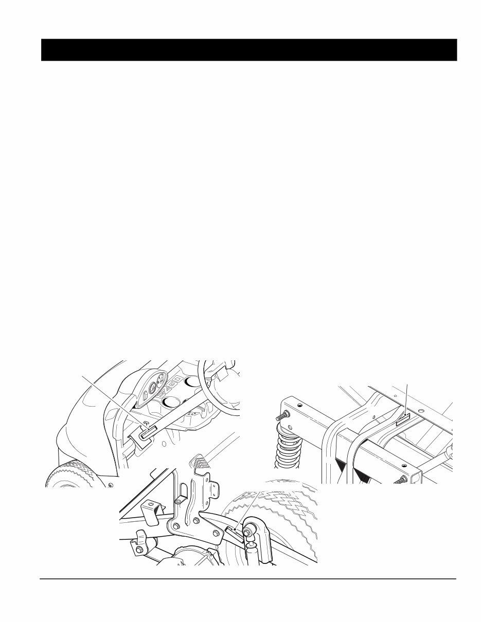
SERIAL NUMBER LOCATION
Three serial number and manufacture date code labels are on the vehicle. One is placed on the steering column, the
second is located on the frame member under the front splash shield on the driver side and the third is located on the
passenger side frame rail at the rear of the vehicle.
In order to obtain correct components for the vehicle, the manufacture date code, serial number and vehicle model must
be provided when ordering service parts.
Serial Number
Serial Number
Serial Number
HOW TO USE THE SERVICE PARTS MANUAL
Page viii
HOW TO USE THE SERVICE PARTS MANUAL
1. WHEN THE PART NUMBER IS NOT KNOWN
• Determine the function and application of the part required. Turn to the TABLE OF CONTENTS and select the
most appropriate component description.
• Turn to the page number indicated and locate the part description in the parts list. Read the full accompanying
description for specific information regarding the part that was not shown in the index.
• From the parts list, obtain the item number assigned to it and confirm that the part selected is correct by verifying
it with the pictorial representation on the illustrated page.
Should an asterisk (*) appear in the part number column on the parts list page, read upwards until a part number is
found. The part number is the lowest assembly sold by Service Parts. The asterisk (*) indicates that the part depicted is
not available for purchase.
NOTE: Descriptions are indented under the assembly that they are used on. That assembly is, in turn listed under the
assembly that it is used on. This process is repeated until the highest final assembly is reached.
To facilitate the maintenance and repair of the vehicle, a Technician’s Repair and Service Manual is
available from the Service Parts Department.
37
28
46
39
40
21
22
23
71
24
26
27
25
38
43
48
49
57
60
58
61
54
54
68
64
67
65
41
42
70
63
44
59
Front of Vehicle
55
55
52
53
45
2
34
33
32
31
30
5
3
4
12
13
14
15
16
17
18
11
10
8
9
6
47
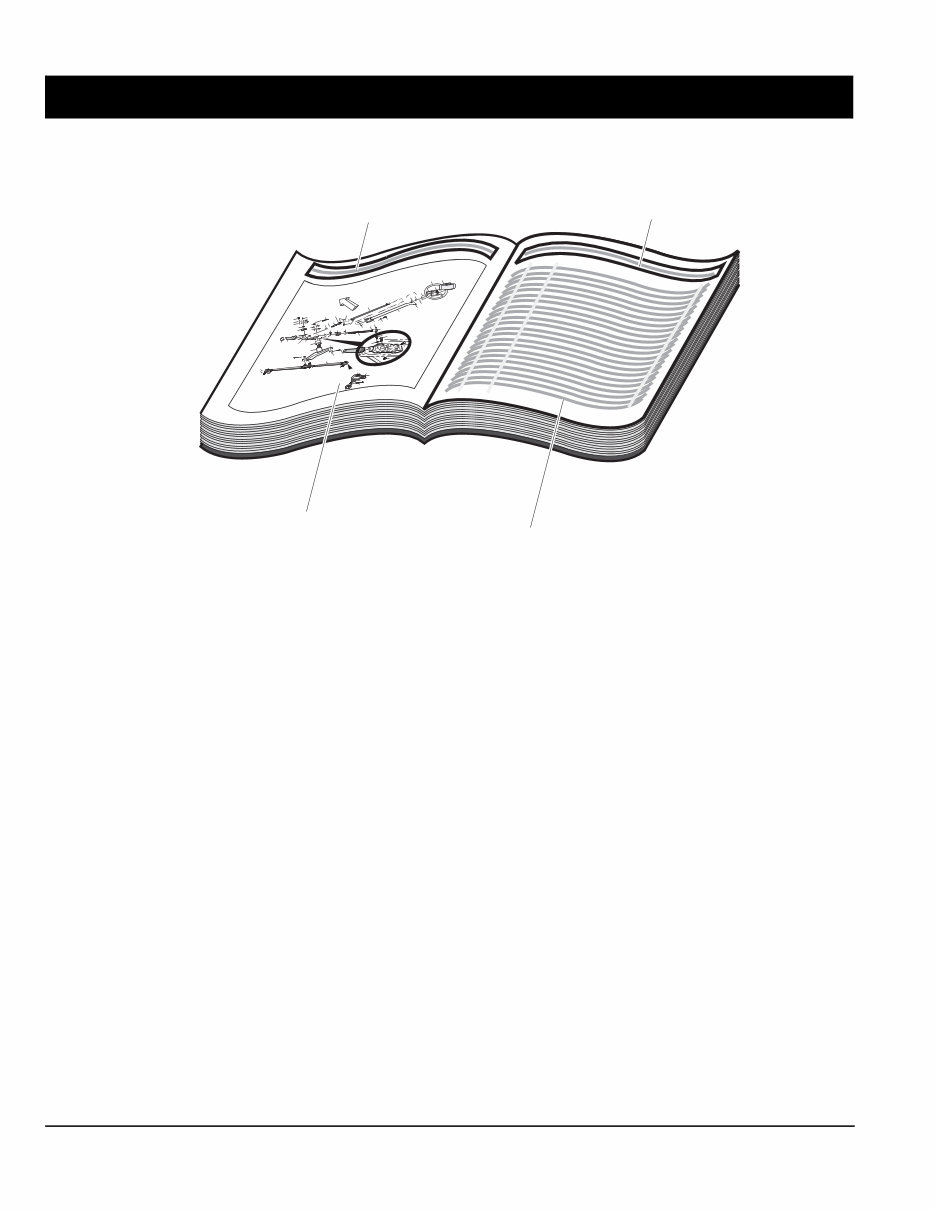
Title
Title
Left hand illustration page
(continued on right hand page
if required)
Parts list (continued on
rear of page if required)
You're Reading a Preview
What's Included?
Fast Download Speeds
Online & Offline Access
Access PDF Contents & Bookmarks
Full Search Facility
Print one or all pages of your manual
$33.99
Viewed 82 Times Today


Secure transaction
What's Included?
Fast Download Speeds
Online & Offline Access
Access PDF Contents & Bookmarks
Full Search Facility
Print one or all pages of your manual
$33.99
This is a service parts manual for gasoline-powered golf cars and personal vehicles, including the RXV Golf Car, RXV Freedom, and RXV Shuttle 2 + 2, starting from the model year 2008.
Whether you are a professional mechanic or a DIY enthusiast, this EZ-GO Professional Technician workshop and maintenance repair manual provides comprehensive guidance for tasks ranging from lubrication to more complex procedures like engine rebuilding. Owning this manual is essential for EZ-GO owners who prefer to perform repairs themselves and save money. It contains all the necessary information for repairing, maintaining, or rebuilding your EZ-GO vehicle.


