VOLVO OLYMPIAN, Lorry and Bus Service and Repair Manual
What's Included?
Lifetime Access
Fast Download Speeds
Online & Offline Access
Access PDF Contents & Bookmarks
Full Search Facility
Print one or all pages of your manual
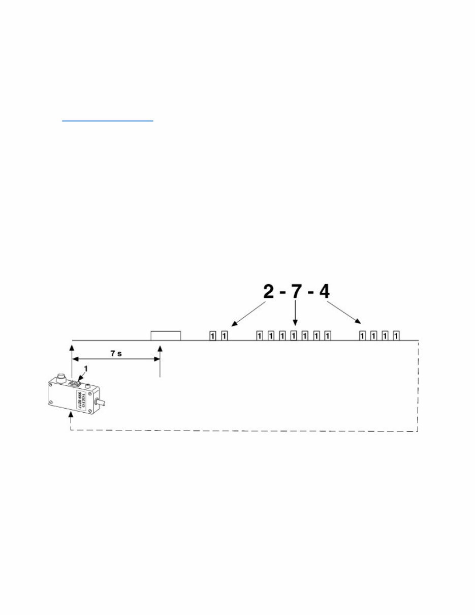
ABS, fault tracing Diagnosis with the help of fault codes The anti-lock brake system control unit has a built-in fault memory if the P/N of the control unit is 8141342, 3944519 or 8141345. The fault memory is read by means of fault codes with the help of a diagnostic tool,Diagnostic tool connection . The Volvo truck diagnostic tool 9998217 is used for buses after the adapter has been supplemented or modified. The alternative is to use a common switch of the lever type with a lamp. Diagnostic tool connection Connect the diagnostic tool to the test socket of the control unit, marked DIA, which is next to the control unit. Then turn the engine power key/ignition key to the driving position. Press the switch on the diagnostic tool (the Volvo trucks tool - the square switch in position 1) until a long flash indicates that the fault code sequence has started. One fault code sequence is shown at a time, i.e., if there is more than one fault, the fault corresponding to the first fault code sequence must be placed in position first and deleted before the next fault code sequence is read. Fault code sequences The parts of the system on which the fault codes supply information are the sensors (7057), the solenoid valves (6013), the relay (3024), and the control unit (9008). Example of a fault code sequence The flashes of the fault diagnosis tool supply the fault codes. Each fault code sequence starts with a long flash which indicates the start of the fault coding. This is followed by the real fault code, which always has three digits e.g. 2, 7, 1. Short flashes indicate a digit in the fault code. For example, two flashes refer to the digit 2, seven flashes refer to the digit 7, and so on. Between each digit in a code there is a pause of 2.5 seconds. The first of the three digits in a fault code indicates the type of control unit, four or six channels. One indicates a 6-channel system and two a 4-channel system. The other digits refer to the fault code in question. Deleting fault codes Page 1 of 11
When deleting all of the fault codes, no remaining fault disappears. Fault codes are deleted as follows: Position the square switch on the diagnostic tool in position 0. Wait until the fault code flashes stop. The fault code can now be deleted. Note: To delete the fault codes using a lever switch and a lamp, disconnect the tool or position the switch in position 0. This table describes the various fault codes in numerical order together with the component in question, the wheel in question, the probable fault and a letter referring to the measure described after the list (ABS, fault tracing ). Control unit type Fault code sequence 1 Fault code sequence 2 Component Diagonal Wheel Fault Ref. Corrective action. Notes -1 -2 -4 -0 -0 - - - No fault registered -1 -2 -4 -6 -6 Relay 3024-1 1 - Low voltage, the relay cannot close A Low voltage in pin 1 or 9 -1 -2 -4 -6 -7 Relay 3024-2 2 - Low voltage, the relay cannot close A Low voltage in pin 9 or 19 -1 -2 -4 -6 -8 Sensor (front axle) 1 F/R No impulse signal from the wheel B -1 -2 -4 -6 -9 Sensor (front axle) 2 F/L No impulse signal from the wheel B -1 -2 -4 -6 -10 Sensor (front axle) 1 F/R Incorrect impedance C Damaged/short- circuited cable -1 -2 -4 -6 -11 Sensor (front axle) 2 F/L Incorrect impedance C Damaged/short- circuited cable -1 -2 -4 -6 -12 Sensor (front axle) 1 F/R Incorrect wheel speed signal D -1 -2 -6 -13 Sensor (front axle) 2 F/L Incorrect wheel speed D Page 2 of 11
-4 signal -1 -2 -4 -7 -0 Sensor (drive axle) 1 R/L Incorrect wheel speed signal B -1 -2 -4 -7 -1 Sensor (drive axle) 2 R/R Incorrect wheel speed signal B -1 -2 -4 -7 -2 Sensor (drive axle) 1 R/L Incorrect impedance C Damaged/short- circuited cable -1 -2 -4 -7 -3 Sensor (drive axle) 2 R/R Incorrect impedance C Damaged/short- circuited cable -1 -2 -4 -7 -4 Sensor (drive axle) 1 R/L Incorrect wheel speed signal D -1 -2 -4 -7 -5 Sensor (drive axle) 2 R/R Incorrect wheel speed signal D -1 -4 -7 -8 Sensor (articulated axle) 1 R/L No impulse signal from the wheel B -1 -4 -7 -9 Sensor (articulated axle) 2 R/R No impulse signal from the wheel B -1 -4 -7 -10 Sensor (articulated axle) 1 R/L Incorrect impedance C Damaged/short- circuited cable -1 -4 -7 -11 Sensor (articulated axle) 2 R/R Incorrect impedance C Damaged/short- circuited cable -1 -4 -7 -12 Sensor (articulated axle) 1 R/L Incorrect wheel speed signal D -1 -4 -7 -13 Sensor (articulated axle) 2 R/R Incorrect wheel speed signal D -1 -2 -4 -8 -0 Control unit 1 - Fault in the control unit H -1 -2 -8 -1 Control unit 2 - Fault in the control unit H Page 3 of 11
-4 -1 -2 -4 -8 -2 Trans signal against ASR 1 - Damaged cable E Pin 12 of the control unit -1 -2 -4 -8 -3 Signal to EDC- 2 - Contact with other cable +/- F/G Pin 29 of the control unit -1 -2 -4 -8 -4 Trans signal against ASR 1 Short-circuit to ground F Pin 12 of the control unit -1 -2 -4 -8 -5 Signal from the EDC- 2 - Incorrect signal, contact with + cable G Pin 28 of the control unit -1 -2 -4 -8 -7 Signal from the EDC- 2 - Contact with +/- cable or damaged cable F/G Pin 28 of the control unit -1 -2 -4 -8 -9 Signal from the EDC- 2 - Contact with + cable or incorrect signal G Pin 28 of the control unit -1 -2 -4 -8 -10 ABS Solenoid valve 1 F/R Short-circuit to ground F Pin 6 of the control unit -1 -2 -4 -8 -11 ABS Solenoid valve 2 F/L Short-circuit to ground F Pin 23 of the control unit -1 -2 -4 -8 -12 ABS Solenoid valve 1 F/R Damaged cable E Pin 6 of the control unit -1 -2 -4 -8 -13 ABS Solenoid valve 2 F/L Damaged cable E Pin 23 of the control unit -1 -2 -4 -8 -14 ABS Solenoid valve 1 F/R Short-circuit to ground F Pin 7 of the control unit -1 -2 -4 -8 -15 ABS Solenoid valve 2 F/L Short-circuit to ground F Pin 24 of the control unit -1 -2 -4 -9 -0 ABS Solenoid valve 1 F/R Damaged cable E Pin 7 of the control unit -1 -9 -1 ABS Solenoid 2 F/L Damaged E Pin 24 of the Page 4 of 11
-2 -4 valve cable control unit -1 -2 -4 -9 -2 ABS Solenoid valve 1 R/L Short-circuit to ground F Pin 21 of the control unit -1 -2 -4 -9 -3 ABS Solenoid valve 2 R/R Short-circuit to ground F Pin 4 of the control unit -1 -2 -4 -9 -4 ABS Solenoid valve 1 R/L Damaged cable E Pin 21 of the control unit -1 -2 -4 -9 -5 ABS Solenoid valve 2 R/R Damaged cable E Pin 4 of the control unit -1 -2 -4 -9 -6 ABS Solenoid valve 1 R/L Short-circuit to ground F Pin 22 of the control unit -1 -2 -4 -9 -7 ABS Solenoid valve 2 R/R Short-circuit to ground F Pin 5 of the control unit -1 -2 -4 -9 -8 ABS Solenoid valve 1 R/L Damaged cable E Pin 22 of the control unit -1 -2 -4 -9 -9 ABS Solenoid valve 2 R/R Damaged cable E Pin 5 of the control unit -1 -9 -10 ABS solenoid valve, articulated axle 1 R/L Short-circuit to ground F Pin 47 of the control unit -1 -9 -11 ABS solenoid valve, articulated axle 2 R/R Short-circuit to ground F Pin 45 of the control unit -1 -9 -12 ABS solenoid valve, articulated axle 1 R/L Damaged cable E Pin 47 of the control unit -1 -9 -13 ABS solenoid valve, articulated axle 2 R/R Damaged cable E Pin 45 of the control unit -1 -9 -14 ABS solenoid valve, articulated axle 1 R/L Short-circuit to ground F Pin 48 of the control unit -1 -9 -15 ABS solenoid valve, articulated axle 2 R/R Short-circuit to ground F Pin 46 of the control unit -1 -10 -0 ABS solenoid 1 R/L Fault in the E Pin 48 of the Page 5 of 11
valve, articulated axle cable control unit -1 -10 -1 ABS solenoid valve, articulated axle 2 R/R Fault in the cable E Pin 46 of the control unit -1 -2 -4 -10 -2 ASR Solenoid valve 1 R/L Short-circuit to ground -1 -2 -4 -10 -3 ASR Solenoid valve 2 R/R Short-circuit to ground -1 -2 -4 -10 -4 ASR Solenoid valve 1 R/L Damaged cable E Pin 2 of the control unit -1 -2 -4 -10 -5 ASR Solenoid valve 2 R/R Damaged cable E Pin 20 of the control unit -1 -2 -4 -10 -7 Relay 3044,30450,3046 2 - Contact with + cable G Pin 11 of the control unit -1 -2 -4 -10 -8 Signal to the transmission 1 - Activation time exceeded, ASR K Pin 12 of the control unit -1 -2 -4 -10 -9 Signal to the transmission 2 - Activation time exceeded, ASR K -1 -2 -4 -11 -12 ABS Solenoid valve 1 F/R Contact with + cable L -1 -2 -4 -11 -13 ABS Solenoid valve 2 F/L Contact with + cable L -1 -2 -4 -11 -14 ABS Solenoid valve 1 R/L Contact with + cable L -1 -2 -4 -11 -15 ABS Solenoid valve 2 R/R Contact with + cable L -1 -12 -0 ABS solenoid valve, articulated axle 1 R/L Contact with + cable L -1 -12 -1 ABS solenoid valve, articulated 2 R/R Contact with + cable L Page 6 of 11
axle -1 -2 -4 -12 -2 ASR Solenoid valve 1 R/L Contact with + cable L -1 -2 -4 -12 -3 ASR Solenoid valve 2 R/R Contact with + cable L -1 -2 -4 -12 -4 ASR Solenoid valve 1 - Contact with + cable L Pin 12 of the control unit -1 -2 -4 -12 -7 Relay 3044,30450,3046 2 - Short-circuit to ground F Pin 11 of the control unit -1 -2 -4 -12 -8 ABS Solenoid valve 1 F/R Contact with + cable G -1 -2 -4 -12 -9 ABS Solenoid valve 2 F/L Contact with + cable G -1 -2 -4 -12 -10 ABS Solenoid valve 1 R/L Contact with + cable G -1 -2 -4 -12 -11 ABS Solenoid valve 2 R/R Contact with + cable G -1 -12 -12 ABS solenoid valve, articulated axle 1 R/L Contact with + cable G -1 -12 -13 ABS solenoid valve, articulated axle 2 R/R Contact with + cable G -1 -2 -4 -12 -14 ASR Solenoid valve 1 R/L Contact with + cable G -1 -2 -4 -12 -15 ASR Solenoid valve 2 R/R Contact with + cable G -1 -2 -4 -13 -0 ASR Solenoid valve 1 - Contact with + cable G Pin 12 of the control unit -1 -2 -4 -13 -4 Relay 3024-1 1 - Relay does not open M -1 -13 -5 Relay 3024-2 2 - Relay does M Page 7 of 11
-2 -4 not open -1 -2 -4 -13 -6 Control unit 1 - Fault in the control unit H -1 -2 -4 -13 -7 Control unit 2 - Fault in the control unit H -1 -2 -4 -13 -8 Control unit 1 - Overvoltage N -1 -2 -4 -13 -9 Control unit 2 - Overvoltage N -1 -2 -4 -13 -10 Control unit 1 - Fault in the control unit H -1 -2 -4 -13 -11 Control unit 2 - Fault in the control unit H -1 -2 -4 -13 -12 Control unit 1 - Fault in the control unit H -1 -2 -4 -13 -13 Control unit 2 - Fault in the control unit H -1 -2 -4 -13 -14 Control unit 1 - Fault in the control unit H -1 -2 -4 -13 -15 Control unit 2 - Fault in the control unit H -1 -2 -4 -14 -0 Control unit 1 - Fault in the control unit H -1 -2 -4 -14 -1 Control unit 2 - Fault in the control unit H -1 -2 -4 -14 -2 Control unit 1 - Fault in the control unit H -1 -2 -4 -14 -3 Control unit 2 - Fault in the control unit H Page 8 of 11
Action The following tips should help to locate the fault more quickly. Fault tracing is now carried out using a multimeter. -1 -2 -4 -14 -4 Control unit 1 - Fault in the control unit H -1 -2 -4 -14 -5 Control unit 2 - Fault in the control unit H -1 -2 -4 -14 -6 ABS Solenoid valve 1 - Activation time exceeded, ABS K -1 -2 -4 -14 -7 ABS Solenoid valve 2 - Activation time exceeded, ABS K -1 -2 -4 -14 -8 ASR Solenoid valve 1 R/L Activation time exceeded, ABS K -1 -2 -4 -14 -9 ASR Solenoid valve 2 R/R Activation time exceeded, ABS K -1 -2 -4 -14 -10 Control unit 1 - Fault in the control unit H -1 -2 -4 -14 -11 Control unit 2 - Fault in the control unit H -1 -2 -4 -14 -12 Control unit 1 - Fault in the control unit H -1 -2 -4 -14 -13 Control unit 2 - Fault in the control unit H -1 -2 -4 -14 -14 Control unit 1 - Fault in the control unit H -1 -2 -4 -14 -15 Control unit 2 - Fault in the control unit H Reference Fault Check Page 9 of 11
A Voltage drop Voltage measured at pins 1, 9 or 19 is very low. (Relay not activated). Check the cables and the power supply. The relay or fuse might be damaged. B No wheel speed signal (electrical fault). Check the sensor cables and connections for poor contact or a short circuit. Check the toothed wheels and sensors for damage. Also check the air columns for loose bearings, the positions of the sensors and the voltage in the sensors. C Incorrect impedance (electrical fault or short circuit). Fault, poor contact or short circuit. Check the cables and sensor. D Unlikely wheel speed signal. Measure the voltage in the sensor and compare it with the correct voltage. The air column between the sensor and the toothed wheel might be very large. (Check for a possible loose bearing). Check to ensure that the toothed wheel assembly is not warped and that the bus tyres are of the correct size. 1 . Maximum size difference between front and rear tyres: 5%. E Fault in the cable. The cable between the control unit and the component has been temporarily or permanently broken. F Short-circuit to ground. The output signals from the control unit have been temporarily or permanently short-circuited to ground. G Contact with + cable (incorrect impulse). The output from the control unit or connected component has a temporary overload to another interfering cable. H Fault in the control unit. Replace the control unit. K ABS/ASR activated for a long time, e.g. when a wheel has locked. (This could occur when driving on a rural road). Locking permanently prohibited on the drive axle wheel (i.e. more than 60 seconds). Check that the acceleration deduction function is working. Also check that the correct wheel has been installed (maximum size difference 5%) and that the toothed wheel has the correct number of teeth. L Contact with + cable (electrical discharge). The prohibited voltage in the component in question is causing operating deficiencies in the Page 10 of 11
The LORRY AND BUS Service and Repair Manual is a comprehensive guide for fixing problems in your vehicle. Whether you are a professional mechanic or a DIY enthusiast, these manuals provide detailed instructions and procedures for repairing your bus. The manual includes technical data, diagrams, a complete list of bus parts, and illustrations to assist with the repair process.
These manuals are invaluable for immediate repairs and the maintenance of your vehicle. They cover all models and repairs from A-Z, providing step-by-step instructions, wiring schematics, and specifications for ease of repair. The information contained in the manual is the same as that used by the company's engineers, ensuring accuracy and reliability.
The manual covers a wide range of topics including maintenance, engine, control system, mechanical, fuel service specifications, emission control, and much more. It is compatible with all versions of Windows and Mac, and is printable for convenience.
With the LORRY AND BUS Repair Manual, you can save time and money by learning to repair and maintain your bus on your own. The manual is designed to be user-friendly, allowing you to print only the pages and diagrams you require. This ensures that the manual remains clean and intact for future use.
Overall, the LORRY AND BUS Repair Manual is a valuable resource for anyone looking to maintain, service, diagnose, and repair their vehicle or bus. It provides the necessary information to keep your bus in top condition, whether for professional or personal use.
Comprehensive instructions and procedures for vehicle repair
Useful for professional mechanics and DIY enthusiasts
Covers all models and repairs from A-Z
Compatible with all versions of Windows and Mac
Recently Viewed
5,521,897Happy Clients
2,594,462eManuals
1,120,453Trusted Sellers
15Years in Business
Price:
Actual Price:
VOLVO OLYMPIAN, Lorry and Bus Service and Repair Manual