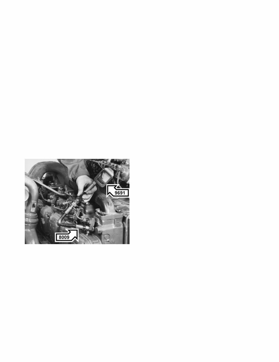
21002-2 Cylinder compression test A compression test is a simple and reliable way of finding out the condition of the engine. The test shows whether or not cylinders and valves are leaking. Low compression pressure on all cylinders indicate worn cylinder liners and/or piston rings. Should a particular cylinder have a low pressure, this may be due to leaking valves, broken piston rings or damaged cylinder head gasket. Special tools: 9998009, 9999691 1 Run the engine warm. 2 Stop the engine and let the mechanical stop control remain pulled out. 3 Remove all the injectors. 4 Fit adapter 9998009. Use the injector retainer to hold the adapter in position. Special tools: 9998009 5 Connect compression gauge 9999691 to the adapter. Special tools: 9999691 6 7/16/2009 Page 1 of 2 Copyright 2004 - Mitchell Repair Information Company, LLC - All Rights Reserved. VOLVO B10M
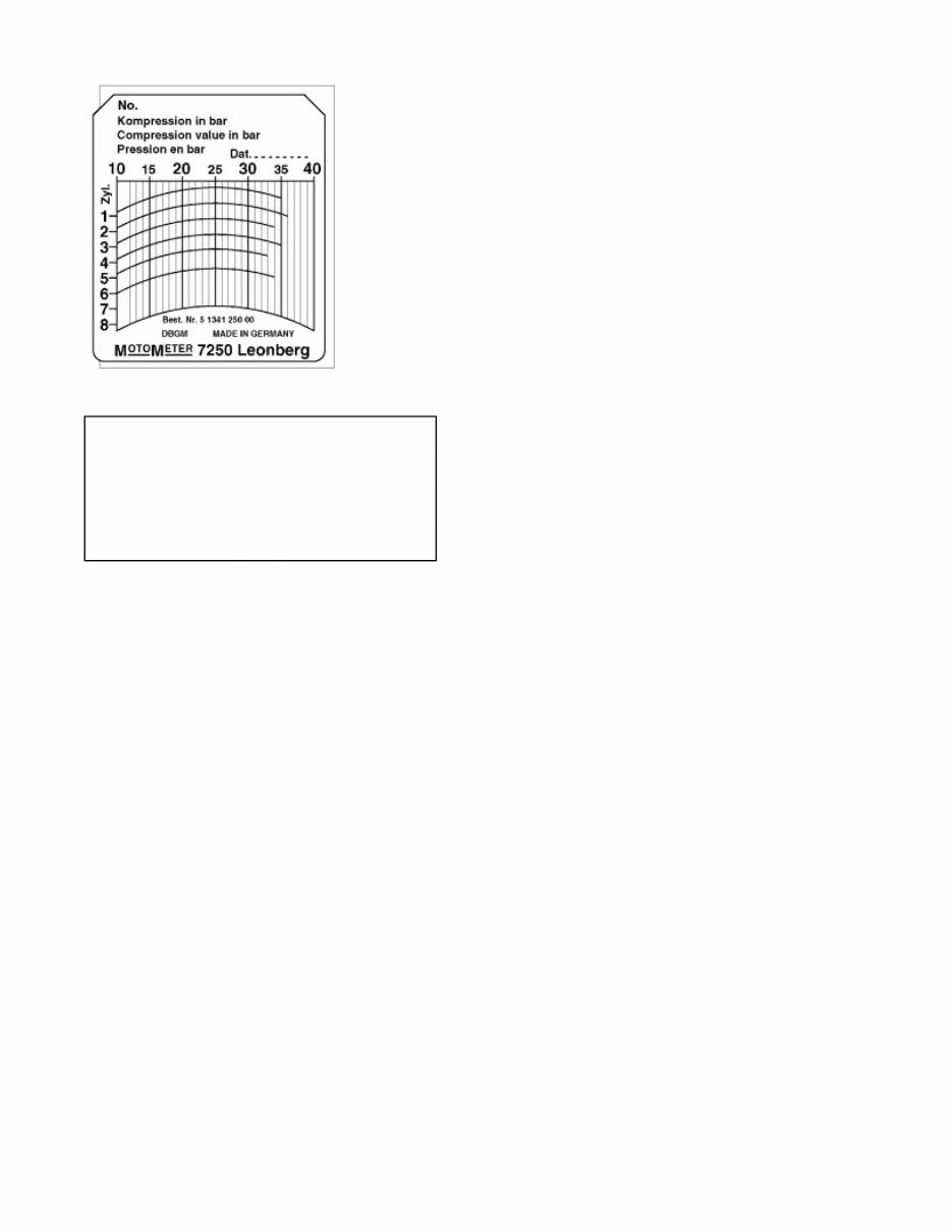
Read the compression pressure at normal starter motor speed (3.7 r/s). It should be: THD 101..... 2.6 Mpa (26 kp/cm²) THD 102..... 2.7 MPa (27 kp/cm²) THD 103-104..... 3.4 MPa (34 kp/cm²) THD 103 KD..... 3.0 MPa (30 kp/cm²) 7/16/2009 Page 2 of 2 Copyright 2004 - Mitchell Repair Information Company, LLC - All Rights Reserved.
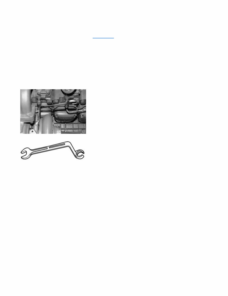
21002-2 Cylinder compression test For further information on special tools, see Special tools . Special tools: 9988539, 9996582, 9998009 1 Run the engine until the normal operation temperature is reached. 2 Switched off the engine and keep the stop control activated. 3 Remove the turbocompressor lubrication and cooling. Note: Carry out this operation to remove the injector nozzle for the 4th cylinder. Use the special tool, according to the illustration, to remove the cooling pipe. 4 Remove the pressure and return pipes from the injectors. 5 Remove the injector nozzles and install the protection caps. Note: If the injector nozzles are stuck in the copper liner, remove them with the help of the tool 9996582. Special tools: 9996582 6 Attach the tool 9998009 in the place of the injector nozzle and fasten it with the injector nozzle cramp and nut. Special tools: 9998009 7 7/16/2009 Page 1 of 2 Copyright 2004 - Mitchell Repair Information Company, LLC - All Rights Reserved.
Connect the compression gauge 9988539 and measure the engine compression. Note: Run the engine until the gauge reaches the maximum read. The starter motor cannot operate for more than 15 seconds. Specifications: 15 seconds 7/16/2009 Page 2 of 2 Copyright 2004 - Mitchell Repair Information Company, LLC - All Rights Reserved.
21070-1 Engine, remove Draining coolant Special tools: 9996049 7/16/2009 Page 1 of 7 Copyright 2004 - Mitchell Repair Information Company, LLC - All Rights Reserved.
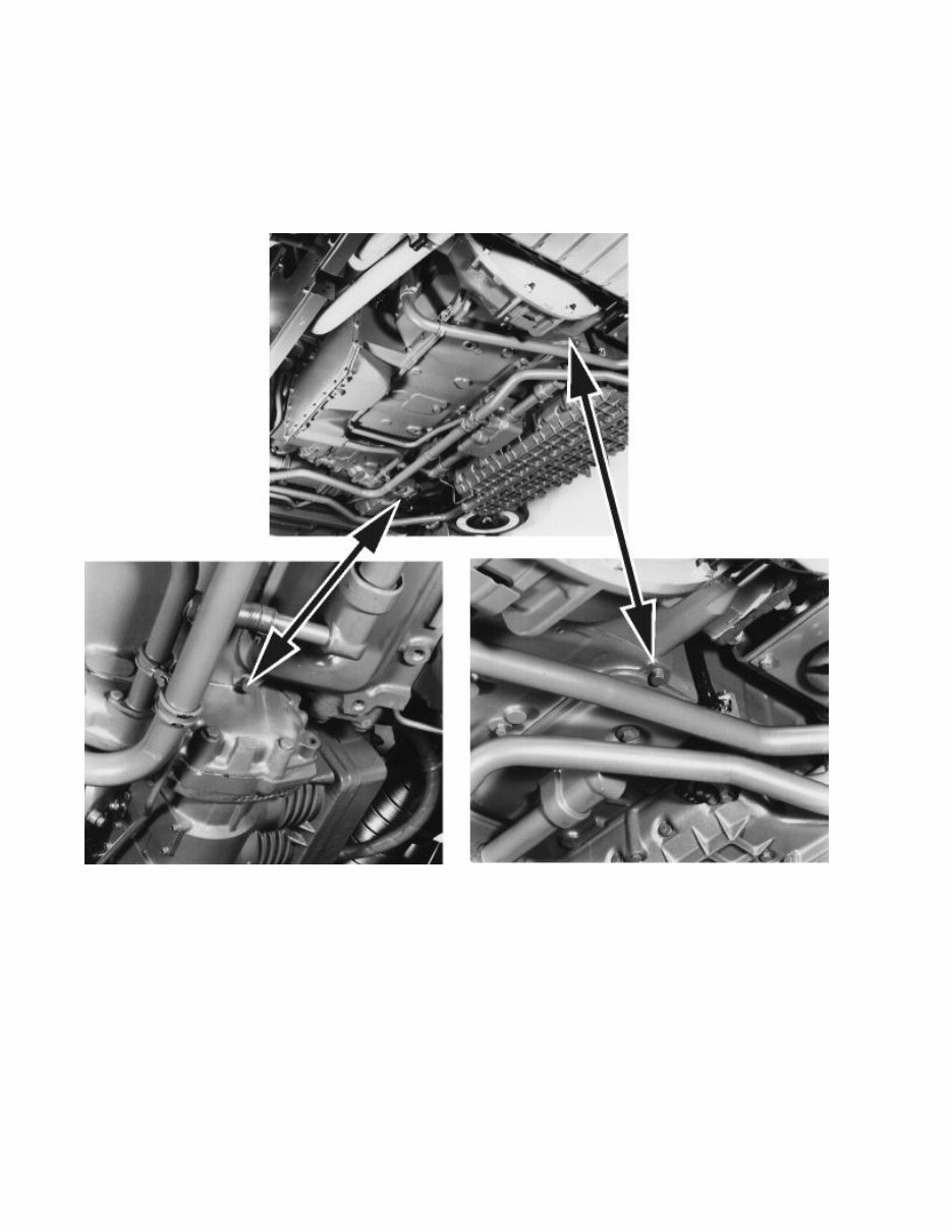
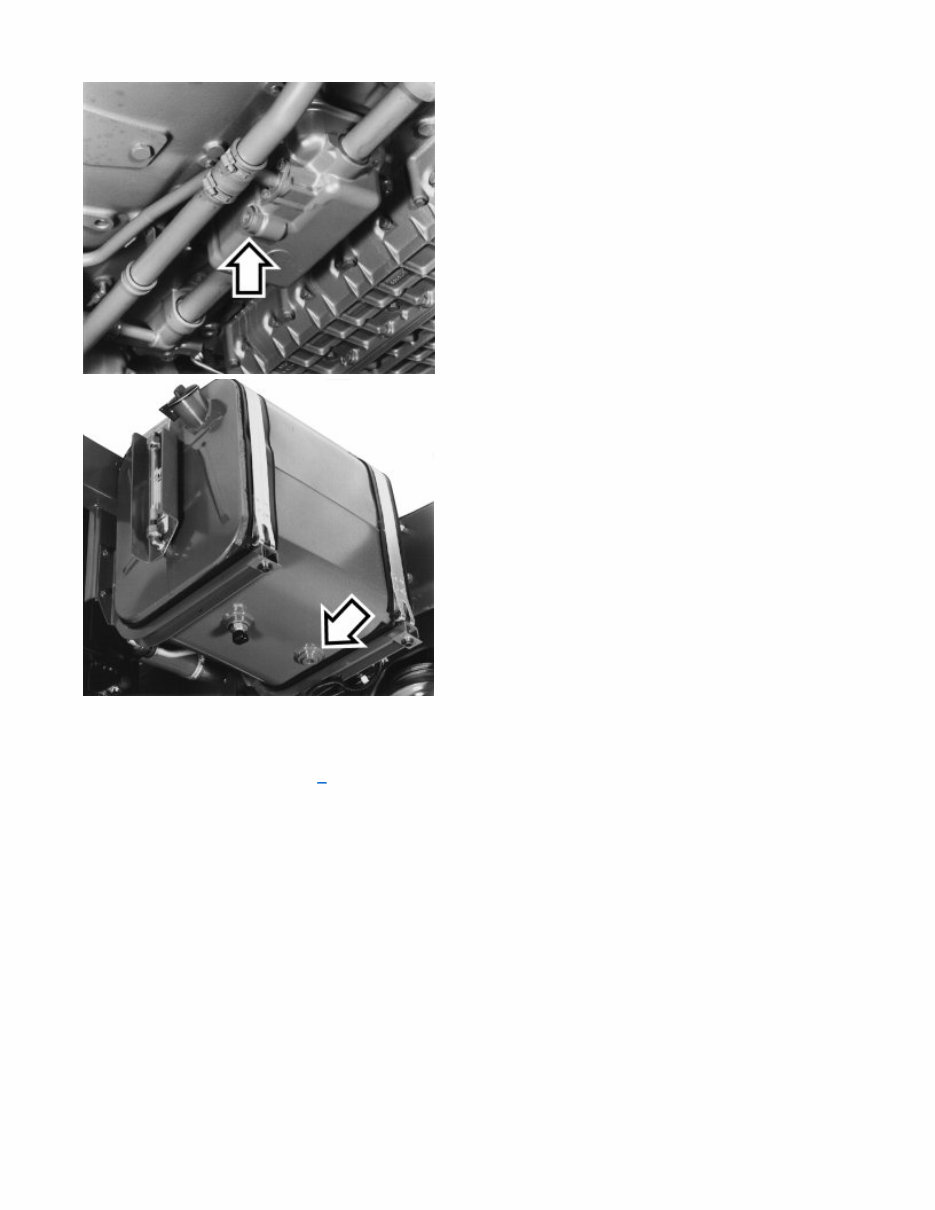
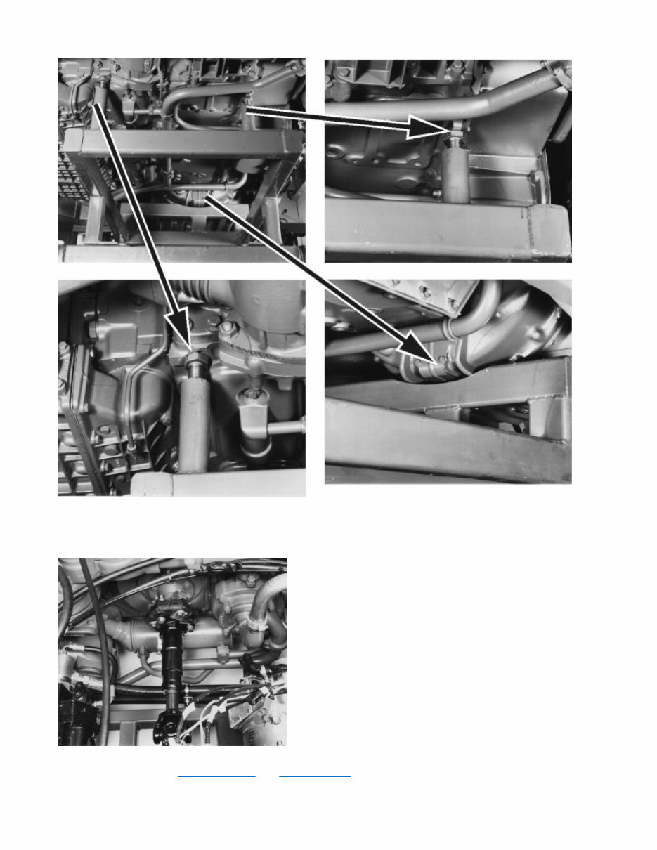
1 The number and location of the drain points varies according to the type of bus. What they all have in common are the radiator and two drain points on the engine. The coolant must be treated just like other potentially dangerous fluids. Draining the oil There are three plugs for draining the oil: one underneath the oil sump; one next to the oil pocket on the inspection cover; and one under the oil tank. 7/16/2009 Page 2 of 7 Copyright 2004 - Mitchell Repair Information Company, LLC - All Rights Reserved.
Tightening torque for drain plugs: 60+15 Nm (6.0+1.5 kgf m). Concerning topping-up oil, refer to 6 . Removing the engine (midway) Special tools: 9988993, 9988894 7/16/2009 Page 3 of 7 Copyright 2004 - Mitchell Repair Information Company, LLC - All Rights Reserved.
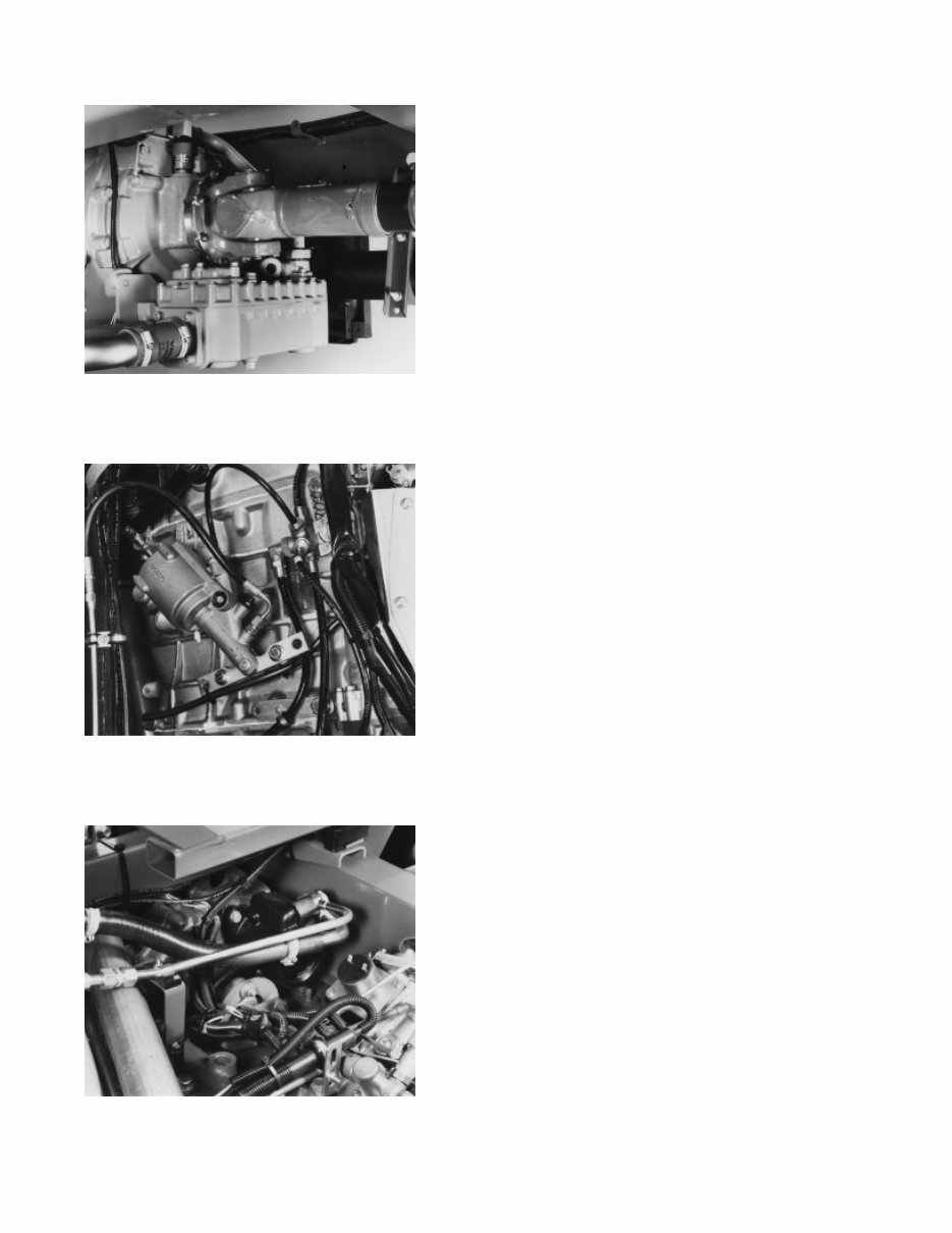
Engine mounts 1 Drain fluids as shown on Draining coolant and Draining the oil . Switch off the isolator switch. Disconnect the fan prop shaft. 7/16/2009 Page 4 of 7 Copyright 2004 - Mitchell Repair Information Company, LLC - All Rights Reserved.
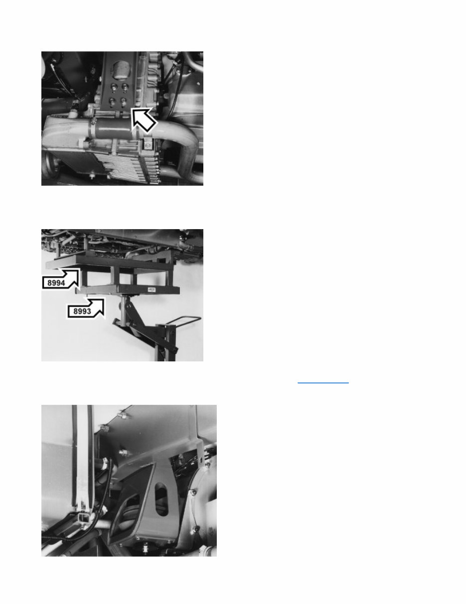
2 Disconnect the prop shaft. 3 Remove the clutch servo. 4 Disconnect the steering servo pump. 7/16/2009 Page 5 of 7 Copyright 2004 - Mitchell Repair Information Company, LLC - All Rights Reserved.
5 Disconnect/detach cables, hoses and pipes. Disconnect gearbox mounts if fitted. 6 Put in place the engine lift trolley and the fixtures. Note the support points in Engine mounts . 7 7/16/2009 Page 6 of 7 Copyright 2004 - Mitchell Repair Information Company, LLC - All Rights Reserved.
The VOLVO B10M Bus Service & Repair Manual is a comprehensive resource for troubleshooting vehicle issues, providing step-by-step instructions and detailed procedures for confident DIY repairs.
As vehicles age, parts deteriorate, and timely replacements are crucial. A reliable repair manual can save time and money by enabling simple part replacements without professional assistance.
This manual offers technical data, diagrams, and an exhaustive list of car parts accompanied by clear pictures, alongside easy-to-follow guides, illustrations, and detailed drawings suitable for novice mechanics.
It includes the same technical information used by company engineers, covering all models and repairs—from routine maintenance and engine control to brakes and steering—with detailed instructions, schematics, wiring diagrams, and specifications.
Compatible with both Windows and Mac systems, this printable manual delivers easy access to crucial information without the hassle of bulky physical books, making it ideal for professional mechanics and DIY enthusiasts.
With this repair manual, vehicle owners can confidently perform simple car repairs, enjoy the satisfaction of tackling do-it-yourself projects, and gain the knowledge needed to overcome any repair challenge.
Get the VOLVO B10M Bus Service & Repair Manual today and take control of maintaining and repairing your own vehicle.