

Honeywell King Bendix RDR 2000 Digital Weather Radar System Pilots Guide
What's Included?
Fast Download Speeds
Online & Offline Access
Access PDF Contents & Bookmarks
Full Search Facility
Print one or all pages of your manual
Pilot’s Guide
RDR 2000
Digital Weather Radar System
B
S a
006-08755-0001 Revision 3

WARNING
Information subject to the export control laws. This document, which includes
any attachments and exhibits hereto, contains information subject to
International Traffic in Arms Regulation (ITAR) or Export Administration
Regulation (EAR) of 1979, which may not be exported, released or disclosed to
foreign nationals inside or outside the U.S. without first obtaining an export
license. Violators of ITAR or EAR may be subject to a penalty of 10 years
imprisonment and a fine of $1,000,000 under 22 U.S.C. 2778 or Section 2410
of the Export Administration Act of 1979. Include this notice with any repro-
duced portion of this document.
COPYRIGHT NOTICE
©1996-1998 AlliedSignal, Inc.
Reproduction of this publication or any portion thereof by any means without
the express written permission of AlliedSignal Electronic and Avionics Systems
is prohibited. For further information contact the Manager, Technical
Publications; AlliedSignal Electronic and Avionics Systems; One Technology
Center; 23500 West 105th Street; Olathe, Kansas 66061. Telephone: (913)
782-0400.

Effective Date: 5/98 RDR 2000 Pilot's Guide: Rev 3
Table of Contents
RDR 2000 OPERATIONAL CONTROLS . . . . . . . . . . . . . . . . . . . . . . . . . . . .1
TEST PATTERN . . . . . . . . . . . . . . . . . . . . . . . . . . . . . . . . . . . . . . . . . . . .4
FAULT ANNUNCIATIONS . . . . . . . . . . . . . . . . . . . . . . . . . . . . . . . . . . . . .4
PREFLIGHT . . . . . . . . . . . . . . . . . . . . . . . . . . . . . . . . . . . . . . . . . . . . . . . . . . . 5
PREFLIGHT WARNINGS . . . . . . . . . . . . . . . . . . . . . . . . . . . . . . . . . . . . .5
THEORY OF OPERATION . . . . . . . . . . . . . . . . . . . . . . . . . . . . . . . . . . . . . . .7
GENERAL . . . . . . . . . . . . . . . . . . . . . . . . . . . . . . . . . . . . . . . . . . . . . . . . .7
RADAR PRINCIPLES . . . . . . . . . . . . . . . . . . . . . . . . . . . . . . . . . . . . . . . .7
WEATHER RADAR PRINCIPLES . . . . . . . . . . . . . . . . . . . . . . . . . . . . . .8
RADAR BEAM ILLUMINATION . . . . . . . . . . . . . . . . . . . . . . . . . . . . . . . .8
RADAR TILT ANGLE CALCULATOR USER INSTRUCTIONS . . .10
RADAR REFLECTIVITY . . . . . . . . . . . . . . . . . . . . . . . . . . . . . . . . . . . . .13
WEATHER DISPLAY CALIBRATION . . . . . . . . . . . . . . . . . . . . . . . . . . .14
WEATHER ATTENUATION COMPENSATION . . . . . . . . . . . . . . . . . . .15
TARGET ALERT . . . . . . . . . . . . . . . . . . . . . . . . . . . . . . . . . . . . . . .17
ALTITUDE RING (RANGE RING) . . . . . . . . . . . . . . . . . . . . . . . . . .18
RADOMES . . . . . . . . . . . . . . . . . . . . . . . . . . . . . . . . . . . . . . . . . . . .18
WEATHER MAPPING AND INTERPRETATION . . . . . . . . . . . . . . . . . . . . .20
OBSERVING WEATHER . . . . . . . . . . . . . . . . . . . . . . . . . . . . . . . . . . . .20
THUNDERSTORMS & TURBULENCE . . . . . . . . . . . . . . . . . . . . . . . . .21
TORNADOES . . . . . . . . . . . . . . . . . . . . . . . . . . . . . . . . . . . . . . . . . . . . .21
HAIL . . . . . . . . . . . . . . . . . . . . . . . . . . . . . . . . . . . . . . . . . . . . . . . . . .22
ICING . . . . . . . . . . . . . . . . . . . . . . . . . . . . . . . . . . . . . . . . . . . . . . . . . .23
SNOW . . . . . . . . . . . . . . . . . . . . . . . . . . . . . . . . . . . . . . . . . . . . . . . . . .23
LIGHTNING AND STATIC DISCHARGES . . . . . . . . . . . . . . . . . . . . . . .24
GROUND MAPPING AND INTERPRETATION . . . . . . . . . . . . . . . . . . . . . .25
LOOKING ANGLE . . . . . . . . . . . . . . . . . . . . . . . . . . . . . . . . . . . . . . . . . .26
OPERATION IN-FLIGHT . . . . . . . . . . . . . . . . . . . . . . . . . . . . . . . . . . . . . . . .27
GENERAL . . . . . . . . . . . . . . . . . . . . . . . . . . . . . . . . . . . . . . . . . . . . . . . .27
TILT MANAGEMENT . . . . . . . . . . . . . . . . . . . . . . . . . . . . . . . . . . . . . . .27
EARLY DETECTION OF ENROUTE WEATHER . . . . . . . . . . . . . .29
SEPARATION OF WEATHER AND GROUND TARGETS . . . . . .29
SHADOWED AREAS . . . . . . . . . . . . . . . . . . . . . . . . . . . . . . . . . . . .32
i

Effective Date: 5/98
RDR 2000 Pilot's Guide: Rev 3
Table of Contents
TARGET RESOLUTION . . . . . . . . . . . . . . . . . . . . . . . . . . . . . . . . .32
RANGE RESOLUTION . . . . . . . . . . . . . . . . . . . . . . . . . . . . . . . . . .32
AZIMUTH RESOLUTION . . . . . . . . . . . . . . . . . . . . . . . . . . . . . . . . .33
PATH PLANNING . . . . . . . . . . . . . . . . . . . . . . . . . . . . . . . . . . . . . . . . . . 33
PATH PLANNING CONSIDERATIONS . . . . . . . . . . . . . . . . . . . . .34
ANTENNA STABILIZATION . . . . . . . . . . . . . . . . . . . . . . . . . . . . . . . . . . . . . 36
CRITERIA . . . . . . . . . . . . . . . . . . . . . . . . . . . . . . . . . . . . . . . . . . . . . . . . 36
PITCH ERRORS . . . . . . . . . . . . . . . . . . . . . . . . . . . . . . . . . . . . . . . . . . . 36
TURN ERRORS . . . . . . . . . . . . . . . . . . . . . . . . . . . . . . . . . . . . . . . . . . . 36
EFFECT ON RADAR STABILIZATION . . . . . . . . . . . . . . . . . . . . . . . . .37
DURING TAKEOFF . . . . . . . . . . . . . . . . . . . . . . . . . . . . . . . . . . . . . 38
SHALLOW-BANKED TURNS . . . . . . . . . . . . . . . . . . . . . . . . . . . . .38
STABILIZATION LIMITS . . . . . . . . . . . . . . . . . . . . . . . . . . . . . . . . .38
STABILIZATION FLIGHT TEST CHECKLIST . . . . . . . . . . . . . . . . . . . .40
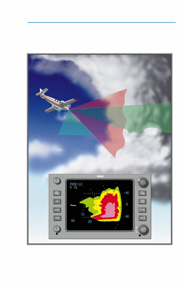
VERTICAL PROFILE (VP) THEORY OF OPERATION . . . . . . . . . . . . . . . .42
VP OPERATION IN-FLIGHT . . . . . . . . . . . . . . . . . . . . . . . . . . . . . . . . . . . . . 42
VERTICAL PROFILE . . . . . . . . . . . . . . . . . . . . . . . . . . . . . . . . . . . . . . . . 42
OPERATION . . . . . . . . . . . . . . . . . . . . . . . . . . . . . . . . . . . . . . . . . . . . . . 43
WEATHER RADAR INTERFERENCE . . . . . . . . . . . . . . . . . . . . . . . . . . . . . .52
OPTIONS . . . . . . . . . . . . . . . . . . . . . . . . . . . . . . . . . . . . . . . . . . . . . . . . . . 55
CHECKLIST . . . . . . . . . . . . . . . . . . . . . . . . . . . . . . . . . . . . . . . . . . . . . . . 55
MOVING-MAP NAVIGATION . . . . . . . . . . . . . . . . . . . . . . . . . . . . . . . . .56
SPECIFICATIONS . . . . . . . . . . . . . . . . . . . . . . . . . . . . . . . . . . . . . . . . . . . . . 57
RDR 2000 SENSOR (ANTENNA, RECEIVER, TRANSMITTER) . . . . .57
INDICATOR IN-182A . . . . . . . . . . . . . . . . . . . . . . . . . . . . . . . . . . . . . . . . 58
APPENDIX: . . . . . . . . . . . . . . . . . . . . . . . . . . . . . . . . . . . . . . . . . . . . . . . . . . 59
LICENSE REQUIREMENTS . . . . . . . . . . . . . . . . . . . . . . . . . . . . . . . . . .59
SAFETY INFORMATION . . . . . . . . . . . . . . . . . . . . . . . . . . . . . . . . . . . . . 62
ii
Effective Date: 5/98 RDR 2000 Pilot's Guide: Rev 3
1
Operational Controls
RDR 2000 OPERATIONAL CONTROLS
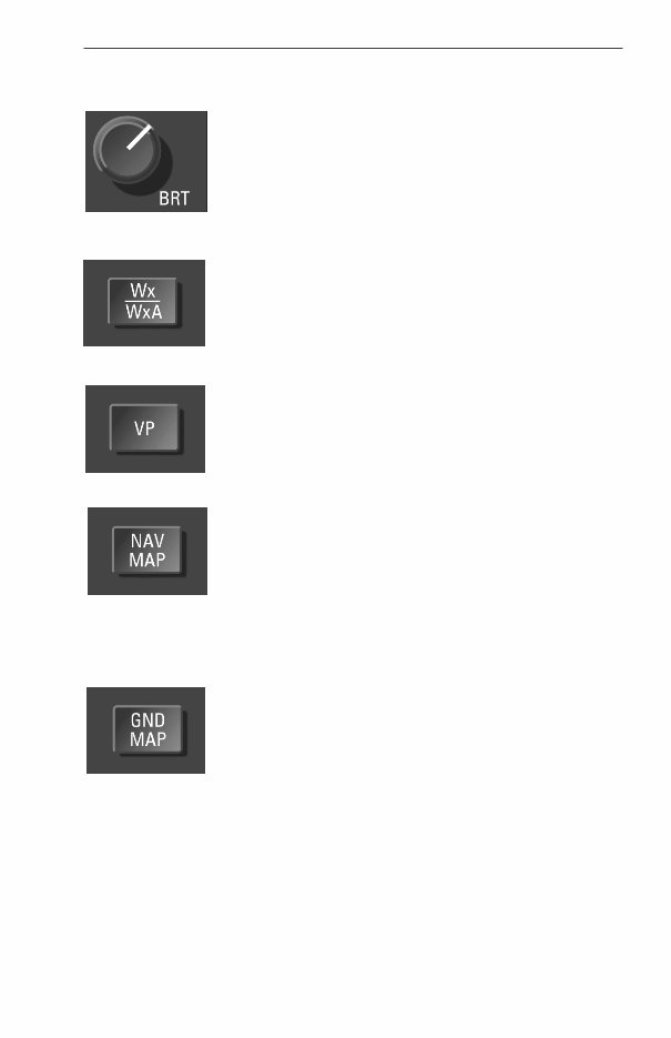
BRT - Controls brightness of the indicator display (CW
rotation for max brightness).
Wx/WxA - Alternately selects between the Wx
(weather) and WxA (weather-alert) modes of operation.
“Wx” or “WxA” will appear in the lower left of the display.
Wx or WxA colors are: Black for no returns, Green for
weak returns, Yellow for moderate returns, Red for
heavy returns and Magenta for intense returns. When
the WxA mode is selected, magenta areas of storms
flash between magenta and black at a 1 HZ rate.
VP - Selects and deselects the Vertical Profile mode of
operation. When VP is selected on the indicator the
radar will provide a vertical scan of ±30 degrees at the
location of the horizontal track line. Selecting the VP
mode of operation will not change the selected mode of
operation: TST, Wx, WxA or GND MAP. Once in VP,
these modes may be changed as desired. VP will
engage from the NAV MAP mode, but NAV data will not
be displayed during VP operation.
NAV MAP - Places indicator in navigation mode so
that preprogrammed waypoints may be displayed. If
other modes are also selected, the NAV display will be
superimposed on them. This button is effective only if
an optional radar graphics unit and Flight Management
System is installed. If activated without these units, NO
NAV will appear at lower left of screen. The radar will
display weather when NAV MAP is selected if the radar
selector is in the ON position.
GND MAP - Places the radar system in ground map-
ping mode. Gain control capability is configurable at
installation to be enabled or disabled in ground map
mode. Ground map colors are: green for weak returns,
yellow for moderate returns and magenta for intense
returns. “MAP” will appear on the lower left of the dis-
play.
Effective Date: 5/98
RDR 2000 Pilot's Guide: Rev 3
Operational Controls
2
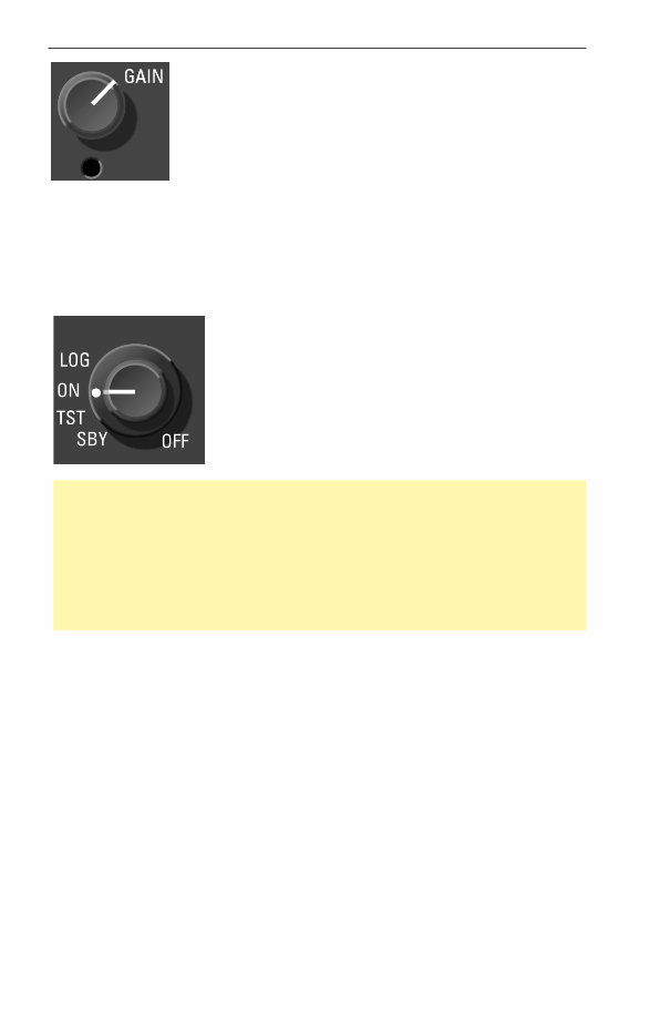
GAIN - The gain knob adjusts the radar gain from 0 to
-20 dB (CCW rotation reduces gain). The gain knob will
only function when in the MAP mode.
LOG - Used when Bendix/King radar graphics units are installed. A
listing of the latitudes and longitudes of selected waypoints are dis-
played. When a compatible navigation source is installed, the selected
VOR frequencies along with bearings and distances are also displayed.
The radar transmits in the LOG mode, unless a Bendix/King radar
graphics unit (IU-2023, GC-360A or GC-381A) is installed.
ON - Selects the normal condition of operation for
weather detection and/or other modes of opera-
tion. The system will transmit after a 60 second
warm-up time is completed. The radar system ini-
tializes to the Wx mode, 80 nm.
Note: The 60 second warm up period can be monitored upon power up
of the system. When the knob is switched directly from OFF to ON mode
(or LOG mode with no Bendix/King radar graphics unit installed), the dis-
play will blank. As the radar sweeps the blue/white will grow outward.
Just before the warm up period is complete, the screen will turn black for
a few seconds, then the radar will begin transmitting and the screen will
display radar returns. No radar transmissions occur until the warm up
period is complete.
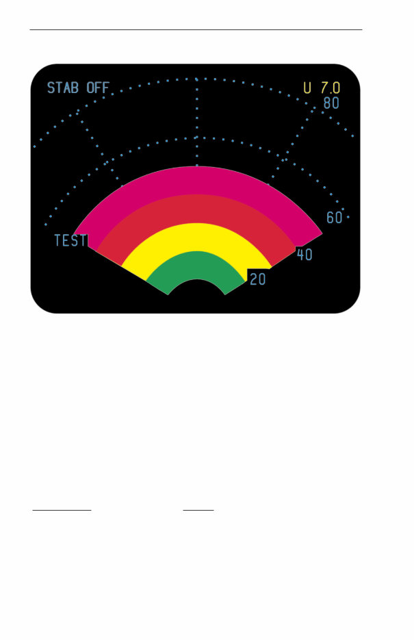
TST - The multicolored arc display test pattern is displayed in this mode
of operation. The test pattern (typical 4-color test pattern on page 4) is
initialized and sized to fit the 80 nm range and can also be scaled with
the range select buttons. No radar transmissions occur while TST is
selected. TEST will appear in the lower left of the display.
STAB OFF is always displayed in top left.
SBY - Fully energizes the system circuitry but no radar transmissions occur
in the SBY mode of operation. The antenna is parked at 0 degrees azimuth
and 30 degrees tilt down with the antenna drive motors locked. In the
standby mode of operation, NAV MAP, checklist and TCAS traffic can be
activated with a Bendix/King radar graphics unit (IU-2023B, GC-360A,
GC-362A or GC-381A) installed. SBY will appear in the lower left of the dis-
play.
Effective Date: 5/98 RDR 2000 Pilot's Guide: Rev 3
3
Operational Controls
OFF - Removes primary power from the radar indicator, but the radar
still has power applied. The radar will remain active with no radar trans-
missions occurring, for up to a maximum time of 30 seconds. This time
delay allows time to park the antenna at 0 degrees azimuth and 30
degrees tilt down.
Note: The only way to remove primary power from the radar is to pull
the radar circuit breaker.
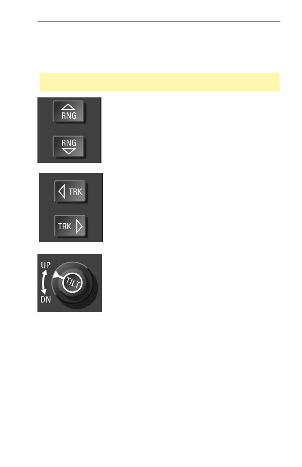
RNG - Clears the display and advances the indi-
cator to the next range. The upper button increases
range, the lower button decreases it. The
RDR 2000 display ranges are: 10, 20, 40, 80, 160,
240 nm. The selected range is displayed in the
upper right corner of the display with the range ring
distance displayed along the right edge.
TRK - Provides a yellow track centerline for vertical
profile. With the radar on and a track button
pushed, the track line position moves left or right in
1 degree increments at a rate of about 15 degrees
per second. When Vertical Profile mode is selected,
the antenna scans the slice at the track line azimuth
position. While in Vertical Profile mode, the TRK
buttons move the slice left and right. The azimuth
position of the antenna is displayed on the upper
left corner of the indicator.
TILT - Permits manual adjustment of antenna tilt
15° up or down for best indicator presentation. The
tilt angle is displayed in the upper right corner of the
display.
4
Effective Date: 5/98
RDR 2000 Pilot's Guide: Rev 3
Operational Controls
TEST PATTERN
FAULT ANNUNCIATIONS
Fault annunciations are a method of alerting the pilot that the radar
system is not performing to established standards. Built-in test equip-
ment (BITE) automatically and constantly tests the radar system. If a
fault occurs, the fault annunciation will be presented on the Display unit.
There are two general categories of faults: hard failures and soft
failure/annunciations. By careful observation of the Display, you can
quickly evaluate the condition of the ART 2000.
Hard failures are those which occur when a major function of the system
is lost. Hard failures are typically a total loss of transmitter power,
receiver gain or no antenna scan. Turn off system. Should the system
be left on, further damage to other system components could occur.
Hard Failures:
Annunciation Failure
TX FLT Transmitter failure
429 FLT Loss of 429 bus data
ANT FLT Loss of antenna position
IN FLT 6 Loss of communication between
display and ART

Effective Date: 5/98 RDR 2000 Pilot's Guide: Rev 3
5
Preflight
Note: A TX FLT is indicated if the Strut switch is configured to be active
and the aircraft is on the ground.
Soft failures are those which can cause limited system operation, Radar
data will still be displayed but the flight crew should be aware that the
display does not necessarily represent the true weather. Soft failures
are typically configuration problem, stabilization problems, or some sim-
ilar problem.
Soft Failures:
Annunciation Cause
TX FLT alternating with ANT FLT Configuration module not
being read
STAB LMT Stab. Is exceeding ±30˚
STAB OFF Alert that the scan is not being
stabilized
PREFLIGHT
PREFLIGHT WARNINGS
Do not turn the radar on within 5 feet of containers of flammable or
explosive material. The radar should never be operated during fueling.
Do not attempt to operate the radar until you are completely familiar
with all safety information, including that on pages 58 through 61.
The system always transmits in the ON mode, unless the aircraft is on
the ground and the radar is interfaced to the strut switch. The radar
transmits in LOG mode if the radar is not interfaced to a Bendix/King
radar graphics unit. The system never transmits in the OFF, SBY or TST
modes.
Accomplish the following procedures completely and exactly.
1) Place the radar controls in the following positions:
• Function switch to TST
• Tilt to UP 7 (as shown on the indicator display, upper right corner).
The test pattern will appear. See that the test pattern conforms to the
illustration (The test pattern is sized to fit the 80 nm range and can be
scaled with the range buttons), and observe the “update” action as a
small ripple moves across the display along the outer edge.

6
Effective Date: 5/98
RDR 2000 Pilot's Guide: Rev 3
Preflight
2) With the function switch in TST or SBY, taxi to a clear area where
there are no people, aircraft, vehicles, or metallic buildings within
approximately 100 yards.
3) Rotate the function switch to ON. The indicator will automatically dis-
play in the Wx mode and 80 nm range. Any targets (weather or
ground) will be displayed in green, yellow, red, or magenta. (Note: A
60 second warm up time period is required before the system will
transmit).
4) Press the range-down button to display 40 nm as the maximum range.
5) Press the WxA button and observe that magenta areas (if any) flash.
6) Vary the tilt control manually between 0 and up 15 degrees and
observe that close-in “ground clutter” appears at lower settings and
that any local rain appears at higher settings.
7) Repeat the manual tilt adjustment, this time between the 0 and down
15 degrees positions.
8) Return the function switch to TST or SBY before taxiing!
9) When you are ready for weather detection (after takeoff or just
before), place the function switch to ON and operate the system as
described in the Operation In-Flight section.
You're Reading a Preview
What's Included?
Fast Download Speeds
Online & Offline Access
Access PDF Contents & Bookmarks
Full Search Facility
Print one or all pages of your manual
$48.99
Viewed 77 Times Today


Secure transaction
What's Included?
Fast Download Speeds
Online & Offline Access
Access PDF Contents & Bookmarks
Full Search Facility
Print one or all pages of your manual
$48.99
Get the installation manual for the RDR 2000 Color Weather Radar system. This manual, with the number 006-00643-0007 and revision 7 from July 2002, consists of 128 bookmarked indexed pages. It is a valuable resource for both professional mechanics and DIY enthusiasts.


