Piper Seneca II PA 34 200T Aircraft Workshop & Parts Manual Complete Workshop Service Repair Manual
What's Included?
Lifetime Access
Fast Download Speeds
Online & Offline Access
Access PDF Contents & Bookmarks
Full Search Facility
Print one or all pages of your manual
SENECA II SERVICE MANUAL CARD 1 OF 3 PA-34-200T SENECA II PIPER AIRCRAFT CORPORATION (PART NUMBER 761 590) 1A1
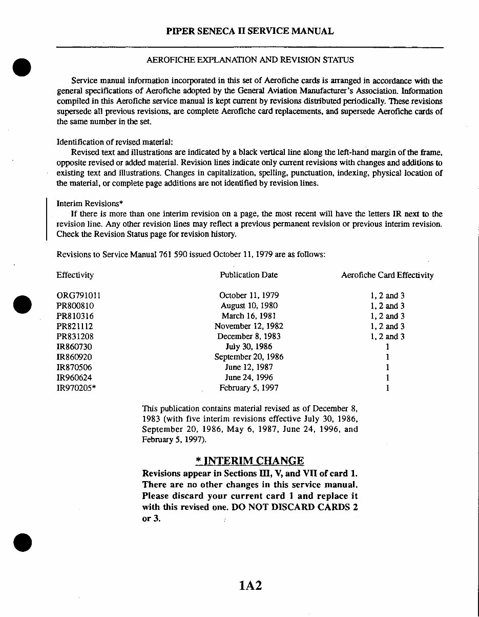
PIPER SENECA II SERVICE MANUAL AEROFICHE EXPLANATION AND REVISION STATUS Service manualinformation incorporated in this set of Aerofiche cards is arranged in accordancewith the general specifications of Aeroficheadoptedby the GeneralAviation Manufacturer'sAssociation. Information compiled in this Aerofiche service manualis keptcurrent by revisionsdistributed periodically. Theserevisions supersedeall previous revisions, are completeAerofiche card replacements, and supersedeAerofiche cards of the samenumberin the set. Identification of revised material: Revisedtext and illustrations are indicated by a black verticalline alongthe left-handmargin of the frame, oppositerevisedor addedmaterial.Revision lines indicateonly currentrevisionswith changesand additions to existing text and illustrations. Changes in capitalization, spelling,punctuation, indexing,physical locationof the material,or complete page additionsare not identified by revision lines. Interim Revisions* If there is morethan one interim revision on a page, the most recent will have the letters IR next to the revision line. Any otherrevision lines may reflect a previouspermanent revisionor previous interimrevision. Check the Revision Status page for revisionhistory. Revisions to Service Manual 761 590 issued October 11, 1979 are as follows: Effectivity Publication Date Aerofiche Card Effectivity ORG791011 October 11, 1979 1, 2 and 3 PR800810 August 10, 1980 1, 2 and 3 PR810316 March 16, 1981 1, 2 and 3 PR821112 November 12, 1982 1, 2 and 3 PR831208 December 8, 1983 1, 2 and 3 IR860730 July 30, 1986 1 IR860920 September20, 1986 1 IR870506 June 12, 1987 1 IR960624 June 24, 1996 1 IR970205* February 5, 1997 1 This publication contains materialrevised as of December8, 1983 (with five interim revisions effective July 30, 1986, September 20, 1986, May 6, 1987, June 24, 1996, and February 5, 1997). * INTERIM CHANGE Revisions appear in Sections III, V, and VII of card 1. There are no other changes in this service manual. Please discard your current card 1 and replace it with this revised one. DO NOT DISCARD CARDS 2 or 3. 1A2
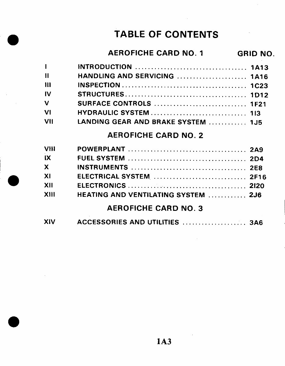
TABLE OF CONTENTS AEROFICHE CARD NO. 1 GRID NO. I II IV V VI VII INTRODUCTION ................................... 1A13 HANDLING AND SERVICING ...................... 1A16 INSPECTION ....................................... 1C23 STRUCTURES...................................... 1 D12 SURFACE CONTROLS ............................. 1 F21 HYDRAULIC SYSTEM .............................. 113 LANDING GEAR AND BRAKE SYSTEM ............ 1J5 AEROFICHE CARD NO. 2 VIII IX X XI XII XIII POWERPLANT ............................... FUEL SYSTEM ............................... INSTRUMENTS .............................. ELECTRICAL SYSTEM ....................... ELECTRONICS ............................... HEATING AND VENTILATING SYSTEM ...... AEROFICHE CARD NO. 3 ..... . 2A9 .2D4 .2E8 2F16 2120 . 2J6 .3A6 XIV ACCESSORIES AND UTILITIES ................... 1A3
1A4 INTENTIONALLYLEFT BLANK
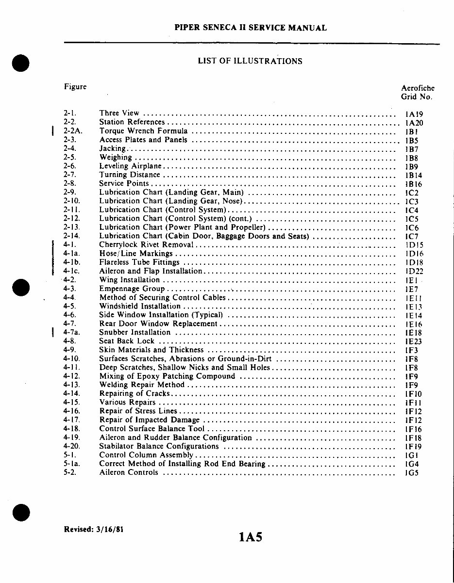
PIPER SENECA II SERVICE MANUAL LIST OF ILLUSTRATIONS Figure Aerofiche Grid No. 2-1. Three View ............................................................... IA19 2-2. Station References .......................................................... IA20 2-2A. Torque Wrench Formula ................................................... IB 1 2-3. Access Plates and Panels .................................................... 1B5 2-4. Jacking ................................................................... B7 2-5. Weighing ................................................................. 1 B8 2-6. Leveling Airplane .......................................................... 1 B9 2-7. Turning Distance .......................................................... IB14 2-8. Service Points ............................................................. B16 2-9. Lubrication Chart (Landing Gear, Main) ..................................... IC2 2-10. Lubrication Chart (Landing Gear, Nose) ....................................... IC3 2-11. Lubrication Chart (Control System) .......................................... IC4 2-12. Lubrication Chart (Control System) (cont.) ................................... 1C5 2-13. Lubrication Chart (Power Plant and Propeller) ................................ IC6 2-14. Lubrication Chart (Cabin Door, Baggage Doors and Seats) ..................... 1C7 4-1. Cherrylock Rivet Removal ..... .......................................... ID15 4-1a. Hose/Line Markings ....................................................... ID16 4-1b. Flareless Tube Fittings ..................................................... ID 18 4-1c. Aileron and Flap Installation ................................................ ID22 4-2. Wing Installation .......................................................... 1E 4-3. Empennage Group .................................... ... .................. IE7 4-4. Method of Securing Control Cables .......................................... IE11 4-5. Windshield Installation ..................................................... E 13 4-6. Side Window Installation (Typical) .......................................... IE 14 4-7. Rear Door Window Replacement ............................................ IE16 4-7a. Snubber Installation ....................................................... IE18 4-8. Seat Back Lock ........................................................... IE23 4-9. Skin Materials and Thickness ............................................... IF3 4-10. Surfaces Scratches, Abrasions or Ground-in-Dirt .............................. IF8 4-11. Deep Scratches, Shallow Nicks and Small Holes ............................... IF8 4-12. Mixing of Epoxy Patching Compound ....................................... 1F9 4-13. Welding Repair Method .................................................... 1F9 4-14. Repairing of Cracks ..................................................... . IF10 4-15. Various Repairs ........................................................... IF11 4-16. Repair of Stress Lines ...................................................... 1F12 4-17. Repair of Impacted Damage ................................................ IF12 4-18. Control Surface Balance Tool ................... ............................ 1F16 4-19. Aileron and Rudder Balance Configuration ................................... IF18 4-20. Stabilator Balance Configurations ........................................... IF19 5-1. Control Column Assembly .................................................. IG1 5-1a. Correct Method of Installing Rod End Bearing ................................ IG4 5-2. Aileron Controls .......................................................... IG5 Revised: 3/16/81 1A5
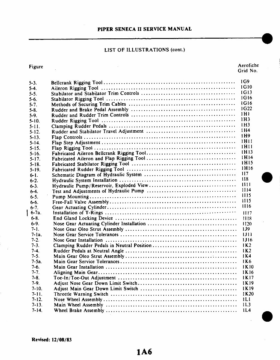
PIPER SENECA II SERVICE MANUAL LIST OF ILLUSTRATIONS (cont.) Figure Aerofiche Grid No. 5-3. Bellcrank Rigging Tool ..................................................... 1G9 5-4. Aileron Rigging Tool ...................................................... IG10 5-5. Stabilator and Stabilator Trim Controls ...................................... 1G 13 5-6. Stabilator Rigging Tool .................................................... IG16 5-7. Methods of Securing Trim Cables ........................................... IG16 5-8. Rudder and Brake Pedal Assembly ......................... ................. 1G22 5-9. Rudder and Rudder Trim Controls .......................................... H I 5-10. Rudder Rigging Tool ...................................................... 1H3 5-11. Clamping Rudder Pedals ................................................... 1H3 5-12. Rudder and Stabilator Travel Adjustment .................................... I H4 5-13. Flap Controls ............................................................. 1H9 5-14. Flap Step Adjustment .............. ........................................ 1 H II 5-15. Flap Rigging Tool ......................................................... 1HI1 5-16. Fabricated Aileron Bellcrank Rigging Tool ........................... ....... 1 H 13 5-17. Fabricated Aileron and Flap Rigging Tool .................................... 1H 14 5-18. Fabricated Stabilator Rigging Tool .......................................... H 15 5-19. Fabricated Rudder Rigging Tool ............................................ H 16 6-1. Schematic Diagram of Hydraulic System ..................... ................ 117 6-2. Hydraulic System Installation ............................................... 118 6-3. Hydraulic Pump/Reservoir, Exploded View ................................... 1111 6-4. Test and Adjustments of Hydraulic Pump .................................... 1114 6-5. Pump Mounting ....................................................... .... 1115 6-6. Free-Fall Valve Assembly ................................................... 1115 6-7. Gear Actuating Cylinder .................................................... 1116 6-7a. Installation of T-Rings .................................................... . . 1117 6-8. End Gland Locking Device ................................................. 1118 6-9. Nose Gear Actuating Cylinder Installation .................................... 1120 7-1. Nose Gear Oleo Strut Assembly .................... ......................... 1J9 7-1a. Nose Gear Service Tolerances ............................................... 1J 1 7-2. Nose Gear Installation ..................................................... IJ16 7-3. Clamping Rudder Pedals in Neutral Position .................................. 1 K2 7-4. Rudder Pedals at Neutral Angle ............................................. 1K2 7-5. Main Gear Oleo Strut Assembly ............................................. 1K4 7-5a. Main Gear Service Tolerances ............................................... 1K6 7-6. Main Gear Installation ..................................................... 1 7-7. Aligning Main Gear ........................................................ 1 K16 7-8. Toe-In/Toe-Out Adjustment ................................................ IK17 7-9. Adjust Nose Gear Down Limit Switch ........................................ 1K19 7-10. Adjust Main Gear Down Limit Switch ....................................... 1K19 7-11. Throttle Warning Switch ................................................... IK20 7-12. Nose Wheel Assembly ...................................................... 1L1 7-13. Main Wheel Assembly ..................................................... 1L3 7-14. Wheel Brake Assembly ..................................................... 1L4 Revised: 12/08/83 1A6
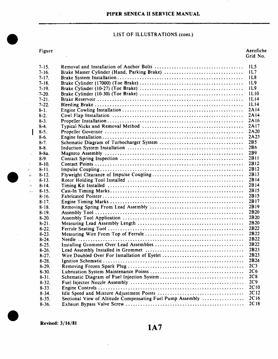
PIPER SENECA II SERVICE MANUAL LIST OF ILLUSTRATIONS (cont.) Figure Aerofiche Grid No. 7-15. Removal and Installation of Anchor Bolts .................................... IL5 7-16. Brake Master Cylinder (Hand, Parking Brake) ................................ 1L7 7-17. Brake System Installation ..................... .............................. L8 7-18. Brake Cylinder (17000) (Toe Brake) .......................................... 1L9 7-19. Brake Cylinder (10-27) (Toe Brake) .......................................... 1L9 7-20. Brake Cylinder (10-30) (Toe Brake) .......................................... IL10 7-21. Brake Reservoir ........................................................... IL14 7-22. Bleeding Brake ........................................................... 1L14 8-1. Engine Cowling Installation ..................... ............................ 2A14 8-2. Cowl Flap Installation ........................................ 2A14 8-3. Propeller Installation ....................................................... 2A 16 8-4. Typical Nicks and Removal Method ......................................... 2A17 8-5. Propeller Governor ........................................................ 2A20 8-6. Engine Installation ......................................................... 2A23 8-7. Schematic Diagram of Turbocharger System .................................. 2B5 8-8. Induction System Installation ............................................... 2B6 8-8a. Magneto Assembly ........................................ 2B9 8-9. Contact Spring Inspection ..................... ............................. 2B11 8-10. Contact Points ......................................................... ... 2B12 8-11. Impulse Coupling .......................................................... 2B12 8-12. Flyweight Clearance of Impulse Coupling ..................................... 2B13 8-13. Rotor Holding Tool Installed ............................................... 2B14 8-14. Timing Kit Installed ........................................ 2B14 8-15. Cast-In Timing Marks ...................................................... 2B15 8-16. Fabricated Pointer ......................................................... 2B 15 8-17. Engine Timing Marks ...................................................... 2B17 8-18. Removing Spring From Lead Assembly ...................................... 2B 19 8-19. Assembly Tool ........................................ 2B20 8-20. Assembly Tool Application ..................... ............................ 2B20 8-21. Measuring Lead Assembly Length ........................................... 2B20 8-22. Ferrule Seating Tool ....................................................... 2B22 8-23. Measuring Wire From Top of Ferrule ........... ............................. 2B22 8-24. Needle ...... ....................................... 2B22 8-25. Installing Grommet Over Lead Assemblies .................................... 2B22 8-26. Lead Assembly Installed in Grommet ........................................ 2B23 8-27. Wire Doubled Over For Installation of Eyelet ................................. 2B23 8-28. Ignition Schematic ......................................................... 2B24 8-29. Removing Frozen Spark Plug ........................................ 2C3 8-30. Lubrication System Maintenance Points ...................................... 2C6 8-31. Schematic Diagram of Fuel Injection System .................................. 2C8 8-32. Fuel Injector Nozzle Assembly .............................................. 2C9 8-33. Engine Controls ........................................................... 2C10 8-34. Idle Speed and Mixture Adjustment Points ................................... 2C 12 8-35. Sectional View of Altitude Compensating Fuel Pump Assembly ................. 2C16 8-36. Exhaust Bypass Valve Screw ................................................ 2C18 Revised: 3/16/81 1 1A7
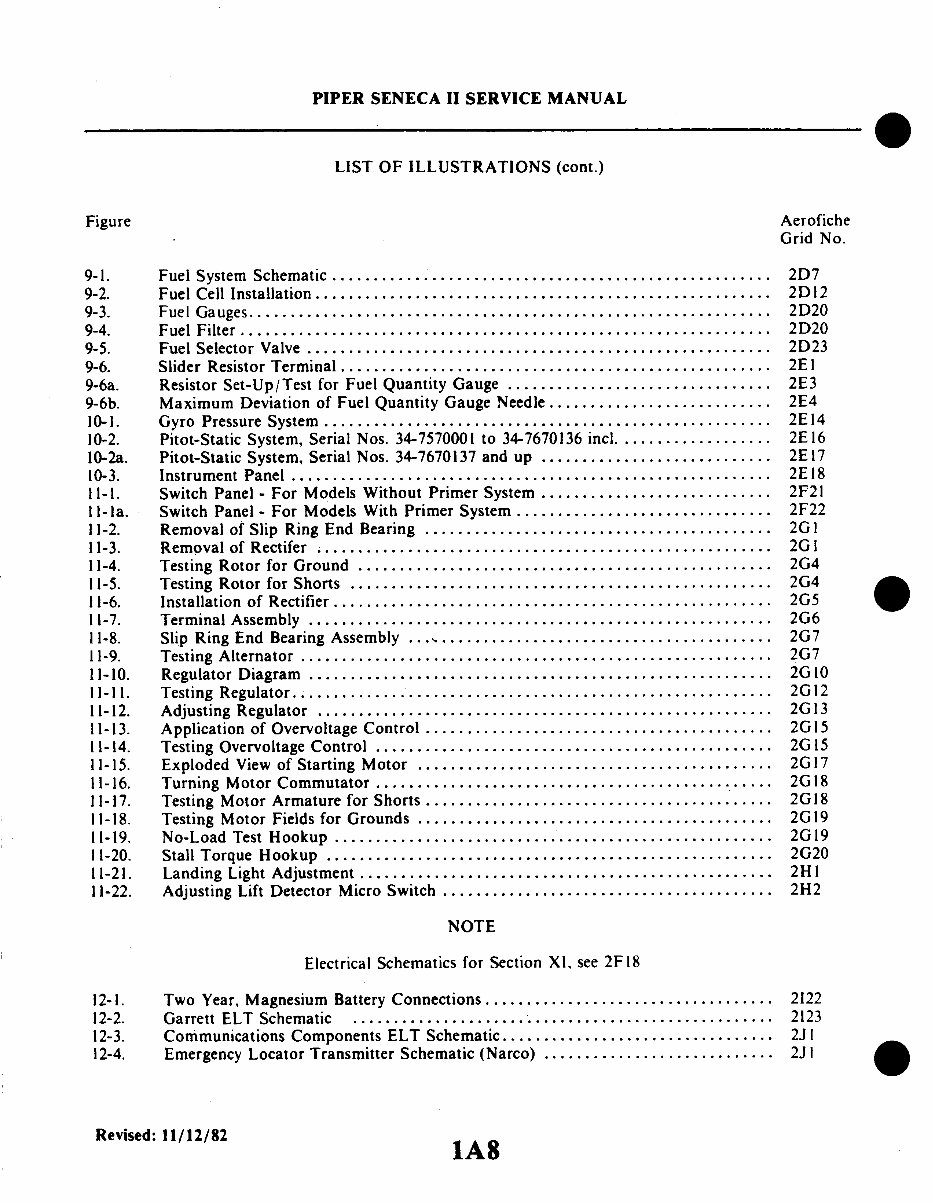
PIPER SENECA II SERVICE MANUAL LIST OF ILLUSTRATIONS (cont.) Figure Aerofiche Grid No. 9-1. Fuel System Schematic ..................................................... 2D7 9-2. Fuel Cell Installation ....................................................... 2D12 9-3. Fuel Gauges ............................................................... 2D20 9-4. Fuel Filter ........................................................... ..... 2D20 9-5. Fuel Selector Valve ........................................................ 2D23 9-6. Slider Resistor Terminal .................................................... 2EI 9-6a. Resistor Set-Up/Test for Fuel Quantity Gauge ................................ 2E3 9-6b. Maximum Deviation of Fuel Quantity Gauge Needle ........................... 2E4 10-1. Gyro Pressure System ...................................................... 2E14 10-2. Pitot-Static System, Serial Nos. 34-7570001 to 34-7670136 incl .................. 2E16 10-2a. Pitot-Static System, Serial Nos. 34-7670137 and up ............................ 2E17 10-3. Instrument Panel ................................................... ....... 2E18 11-1. Switch Panel - For Models Without Primer System ............................ 2F21 11-la. Switch Panel - For Models With Primer System ............................... 2F22 11-2. Removal of Slip Ring End Bearing .......................................... 2G 1 11-3. Removal of Rectifer . .................... .................................. 2G I 11-4. Testing Rotor for Ground .................................................. 2G4 11-5. Testing Rotor for Shorts ................................................... 2G4 11-6. Installation of Rectifier ..................................................... 2G5 11-7. Terminal Assembly ........................................................ 2G6 11-8. Slip Ring End Bearing Assembly ........................................... 2G7 11-9. Testing Alternator ........................................................ . 2G7 11-10. Regulator Diagram .................................................. ...... 2G 10 11-11. Testing Regulator .......................................................... 2G12 11-12. Adjusting Regulator ....................................................... 2G 13 11-13. Application of Overvoltage Control .......................................... 2G15 11-14. Testing Overvoltage Control ................................................ 2G15 11-15. Exploded View of Starting Motor ........................................... 2G17 11-16. Turning Motor Commutator ...................................... ...... .. 2G18 11-17. Testing Motor Armature for Shorts .......................................... 2G18 11-18. Testing Motor Fields for Grounds ........................................... 2G19 11-19. No-Load Test Hookup ............................................ ........ 2G19 11-20. Stall Torque Hookup ...................................................... 2G20 11-21. Landing Light Adjustment .................................................. 2H1 11-22. Adjusting Lift Detector Micro Switch ........................................ 2H2 NOTE Electrical Schematics for Section XI. see 2F18 12-1. Two Year, Magnesium Battery Connections ................................... 2122 12-2. Garrett ELT Schematic ................................. .................. 2123 12-3. Communications Components ELT Schematic ................................. 2J 1 12-4. Emergency Locator Transmitter Schematic (Narco) ............................ 2J I Revised:11/12/82 lA8
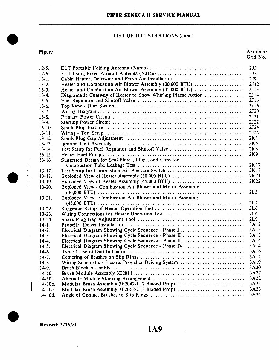
PIPER SENECA II SERVICE MANUAL LIST OF ILLUSTRATIONS (cont.) Figure 12-5. ELT Portable Folding Antenna (Narco) ...................................... 12-6. ELT Using Fixed Aircraft Antenna (Narco) ................................... 13-1. Cabin Heater, Defroster and Fresh Air Installation ............................ 13-2. Heater and Combustion Air Blower Assembly (30,000 BTU) .................... 13-3. Heater and Combustion Air Blower Assembly (45,000 BTU) .................... 13-4. Diagramatic Cutaway of Heater to Show Whirling Flame Action ................ 13-5. Fuel Regulator and Shutoff Valve ........................................... 13-6. Top View - Duct Switch .................................................... 13-7. Wiring Diagram........................................................... 13-8. Primary Power Circuit ..................................................... 13-9. Starting Power Circuit ..................................................... 13-10. Spark Plug Fixture ........................................................ 13-11. Wiring - Test Setup ........................................................ 13-12. Spark Plug Gap Adjustment ................................................ 13-13. Ignition Unit Assembly ..................................................... 13-14. Test Setup for Fuel Regulator and Shutoff Valve .............................. 13-15. Heater Fuel Pump ......................................................... 13-16. Suggested Design for Seal Plates, Plugs, and Caps for Combustion Tube Leakage Test ........................................... 13-17. Test Setup for Combustion Air Pressure Switch ............................... 13-18. Exploded View of Heater Assembly (30,000 BTU) ............................. 13-19. Exploded View of Heater Assembly (45,000 BTU) ............................. 13-20. Exploded View - Combustion Air Blower and Motor Assembly (30,000 BTU) ........................................................... 13-21. Exploded View - Combustion Air Blower and Motor Assembly (45,000 BTU) ........................................................... 13-22. Suggested Setup of Heater Operation Test .................................... 13-23. Wiring Connections for Heater Operation Test ................................ 13-24. Spark Plug Gap Adjustment Tool .......................................... 14-1. Propeller Deicer Installation ................................................ 14-2. Electrical Diagram Showing Cycle Sequence - Phase 1.......................... 14-3. Electrical Diagram Showing Cycle Sequence - Phase II ......................... 14-4. Electrical Diagram Showing Cycle Sequence - Phase III ........................ 14-5. Electrical Diagram Showing Cycle Sequence - Phase IV ........................ 14-6. Typical Use of Dial Indicator ............................................... 14-7. Centering of Brushes on Slip Rings .......................................... 14-8. Wiring Schematic - Electric Propeller Deicing System .......................... 14-9. Brush Block Assembly ..................................................... 14-10. Brush Module Assembly 3E2011 ............................................. 14-1Oa. Alternate Module Stacking Arrangement ..................................... 14-1Ob. Modular Brush Assembly 3E2042-1 (2 Bladed Prop) ........................... 14-10c. Modular Brush Assembly 3E2062-2 (3 Bladed Prop) ........................... 14-10d. Angle of Contact Brushes to Slip Rings ...................................... Aerofiche Grid No. 2J3 2J3 2J9 2J12 2J13 2J14 2J16 2J16 2J20 2J21 2J22 2J24 2J24 2KI 2K5 2K8 2K9 2K17 2K17 2K21 2K22 2L3 2L4 2L6 2L6 2L9 3A12 3A13 3A13 3A14 3A14 3A16 3A17 3A19 3A20 3A22 3A22 3A23 3A23 3A24 Revised: 3/16/81 1A9
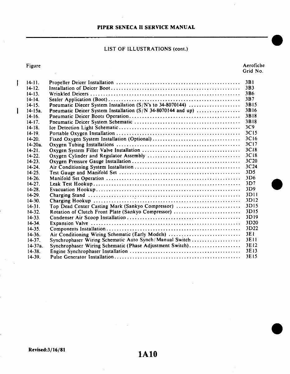
Figure PIPER SENECA II SERVICE MANUAL LIST OF ILLUSTRATIONS (cont.) Aerofiche Grid No. 14-11. 14-12. 14-13. 14-14. 14-15. 14-15a. 14-16. 14-17. 14-18. 14-19. 14-20. 14-20a. 14-21. 14-22. 14-23. 14-24. 14-25. 14-26. 14-27. 14-28. 14-29. 14-30. 14-31. 14-32. 14-33. 14-34. 14-35. 14-36. 14-37. 14-37a. 14-38. 14-39. Propeller Deicer Installation ................................................ Installation of Deicer Boot.................................................. Wrinkled Deicers .......................................................... Sealer Application (Boot) .................................................. Pneumatic Diecer System Installation (S/N's to 34-8070144) .................... Pneumatic Deicer System Installation (S/N 34-8070144 and up) ................. Pneumatic Deicer Boots Operation ........................................... Pneumatic Deicer System Schematic ......................................... Ice Detection Light Schematic ............................................... Portable Oxygen Installation ................................................ Fixed Oxygen System Installation (Optional) .................................. Oxygen Tubing Installations ................................................ Oxygen System Filler Valve Installation ...................................... Oxygen Cylinder and Regulator Assembly .................................... Oxygen Pressure Gauge Installation .......................................... Air Conditioning System Installation ......................................... Test Gauge and Manifold Set ............................................... Manifold Set Operation .................................................... Leak Test Hookup......................................................... Evacuation Hookup........................................................ Charging Stand ........................................................... Charging Hookup ......................................................... Top Dead Center Casting Mark (Sankyo Compressor) ......................... Rotation of Clutch Front Plate (Sankyo Compressor) .......................... Condenser Air Scoop Installation ............................................ Expansion Valve .......................................................... Components Installation .................................................... Air Conditioning Wiring Schematic (Early Models) ............................ Synchrophaser Wiring Schematic Auto Synch/Manual Switch ................... Synchrophaser Wiring Schematic (Phase Adjustment Switch).................... Engine Synchrophaser Installation ........................................... Pulse Generator Installation ................................................. 3B1 3B3 3B6 3B7 3B15 3B16 3B18 3B18 3C9 3C15 3C16 3C17 3C.18 3C18 3C20 3C24 3D5 3D6 3D7 3D9 3D 11 3D12 3D15 3D15 3D19 3D20 3D22 3E1 3E11 3E12 3E13 3E15 Revised:3/16/81 1A10
This complete workshop service repair manual for the Piper Seneca II PA 34 200T aircraft is an essential resource for both professional mechanics and DIY enthusiasts.
The manual covers every service and repair procedure with easy-to-follow step-by-step instructions and pictures, making any job easy to do.
Once downloaded, the manual is yours to keep forever. You can print out specific pages, chapters, or the entire manual, and it can also be saved to your tablet or smartphone.
All models, engines, trim, and transmission types are covered in this comprehensive manual.
It includes high-quality service repair workshop manual that covers all repair procedures from A-Z, ensuring that every repair and service procedure is included.
This downloadable manual is compatible with all PC and MAC computers, tablets, and mobile phones. The only software required is Adobe Reader, which is usually pre-installed or can be downloaded for free.
Upon payment by Visa, MasterCard, or PayPal, the manual will be instantly emailed to the address used during checkout, ensuring prompt delivery.
Customer satisfaction is guaranteed with this comprehensive workshop and parts manual.
Recently Viewed
5,521,897Happy Clients
2,594,462eManuals
1,120,453Trusted Sellers
15Years in Business
Price:
Actual Price:
Piper Seneca II PA 34 200T Aircraft Workshop & Parts Manual Complete Workshop Service Repair Manual