


SARATOGA
MAINTENANCE
MANUAL
CARD 1 OF 3
PA-32-301/301T SARATOGA
PIPER AIRCRAFT
CORPORATIO
(PART NUMBER 761 721)
1A1
PIPER AIRCRAFT
PA-32-301/301T
MAINTENANCE MANUAL
INTRODUCTION.
This PIPER AIRCRAFT Maintenance Manual is prepared in accordance with the GAMA (General
Aviation Manufacturers Association) format. This maintenance manual is dividedinto various Groups which
enable a broad separation of contents (Chapters) within each group.
The various Chapters are broken down into major systems such as Electrical Power, Flight Controls.
Fuel. Landing Gear. etc. The System/Chapters are arranged more or less alphabetically rather than by
precedence or importance. All System/Chapters are assigned a number, which becomesthe first element of a
standardized numbering system. Thus the element "32" of the number series 32-00-00 refers to the
System Chapter on "Landing Gear." All information pertaining to the landing gear will be covered in this
System Chapter.
The major System/Chapters are then broken down into Sub-System/Sections. These sections are
identified by the second element of the standardized numbering system. The number "40" of the basic number
series 32-40-00 is for the "Wheels and Brakes" portion of the landing gear.
The individual units within a Sub-System/ Section may be identified by a third element of the
standardized numbering system. such as 32-40-01. This number could be assigned by the manufacturer to fit
the coverage requirements of the publication.
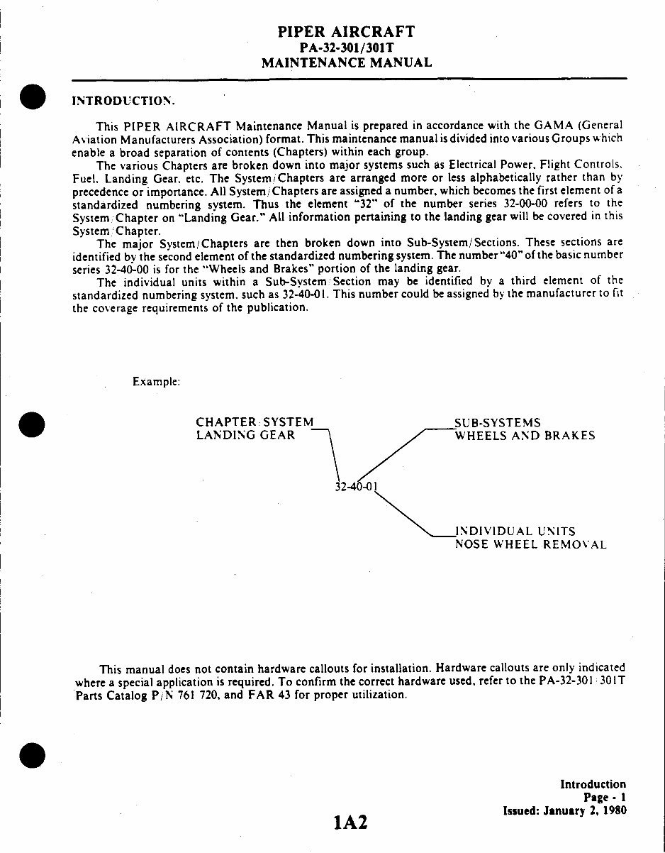
Example:
CHAPTER SYSTEM SUB-SYSTEMS
LANDING GEAR WHEELS AND BRAKES
INDIVIDUAL UNITS
NOSE WHEEL REMOVAL
This manual does not contain hardware callouts for installation. Hardware callouts are only indicated
where a special application is required. To confirm the correct hardware used, refer to the PA-32-301 301T
Parts Catalog P/N 761 720, and FAR 43 for proper utilization.
Introduction
Page- 1
1A2 Issued: January 2, 1980
IA2
PIPER AIRCRAFT
PA-32-301/301T
MAINTENANCE MANUAL
AEROFICHE EXPLANATION AND REVISION STATUS
The Maintenance Manual information incorporated in this setof Aerofiche cards hasbeen arranged in
accordance with the general specifications of Aerofiche adopted by the General Aircraft Manufacturer's
Association. (GAMA). Theinformationcompiled in this Aerofiche Maintenance Manual will bekept current
by revisions distributed periodically.. These revisions will supersede all previous revisions andwill be complete
Aerofiche card replacements and shallsupersede Aerofiche cardsof the same number in the set.
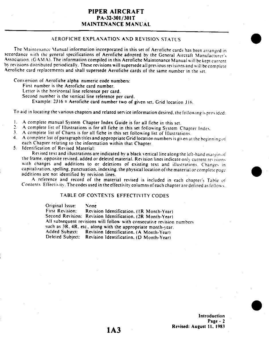
Conversion of Aerofiche alpha numeric code numbers:
First numberis the Aerofiche card number.
Letter is the horizontalline reference per card.
Second numberis the verticalline reference per card.
Example: 2J 16 = Aerofiche card number two of givenset.Grid location J 16.
To aid in locating the various chapters andrelated service information desired. the followingisprovided:
I. A complete manual System ChapterIndex Guide is for all fiche in this set.
2. A complete list of Illustrationsis for all fiche in this set following System ChapterIndex
3. A complete list of Charts
is for all fiche in this set following list of Illustrations.
4. A complete list of paragraph titlesand appropriate Grid locationnumbers is given at thebeginning of
eachChapterrelatingto the informationwithin that Chapter.
5. Identification of Revised Material:
Revised text and illustrations are indicated bya blackvertical linealong theleft-hand marginof
the frame. opposite revised,
addedor deleted material. Revision lines indicate only current revisions,
with changes and additions to or deletions of existing text and illustrations. Changes in
capitalization. spelling. punctuation. indexing. the physical location of the material or complete page
additions are not identified by revision lines.
A reference and record of the material revised is included in each chapter's Table of
Contents Effectivity. The codes used
in the effectivity columns of eachchapteraredefined asfollows.
TABLE OF CONTENTS EFFECTIVITY CODES
Original Issue: None
First Revision:
Revision Identification. (IR Month-Year)
Second Revision: Revision Identification. (2R Month-Year)
All subsequent
revisions will follow with consecutiverevision numbers
such as 3R. 4R. etc.. along with the appropriate month-year.
Added Subject: Revision Identification. (A Month-Year)
Deleted Subject:
Revision Identification. (D Month-Year)
Introduction
Page - 2
1A3 Revised: August II. 1983
IA3
PIPER AIRCRAFT
PA-32-301/301T
MAINTENANCE MANUAL
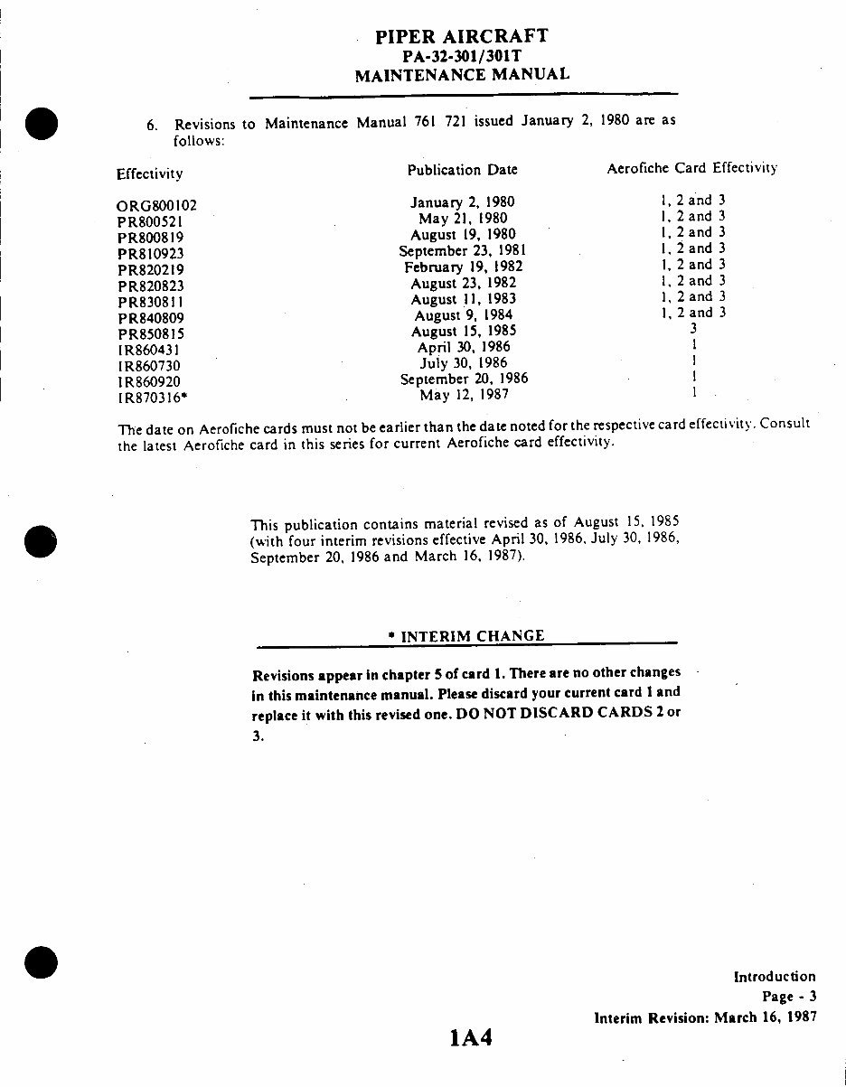
6. Revisions to Maintenance
Manual 761 721 issued January 2, 1980 are as
follows:
Effectivity
Publication Date
Aerofiche Card Effectivity
ORG800102
PR800521
PR800819
PR810923
PR820219
PR820823
PR830811
PR840809
PR850815
IR860431
IR860730
IR860920
IR870316*
January 2, 1980
May 21, 1980
August 19, 1980
September 23, 1981
February 19, 1982
August 23, 1982
August 11, 1983
August 9, 1984
August 15, 1985
April 30, 1986
July 30, 1986
September 20, 1986
May 12, 1987
1, 2 and 3
1, 2and 3
, 2 and 3
, 2 and 3
, 2 and 3
, 2 and 3
, 2 and 3
1, 2 and 3
3
1
1
1
I
The date on Aerofiche cards must not be earlier than the date noted for the respective card effectivity. Consult
the latest Aerofiche card in this series for current Aerofiche card effectivity.
This publication contains material revised as of August 15, 1985
(with four interim revisions effective April 30, 1986, July 30, 1986,
September 20, 1986 and March 16, 1987).
*INTERIM CHANGE
Revisions appear in chapter 5 of card 1. There are no other changes
in this maintenance manual. Please discard your current card 1 and
replace it with this revised one. DO NOT DISCARD CARDS 2 or
3.
Introduction
Page - 3
Interim Revision: March 16, 1987
1A4
PIPER AIRCRAFT
PA-32-301/301T
MAINTENANCE MANUAL
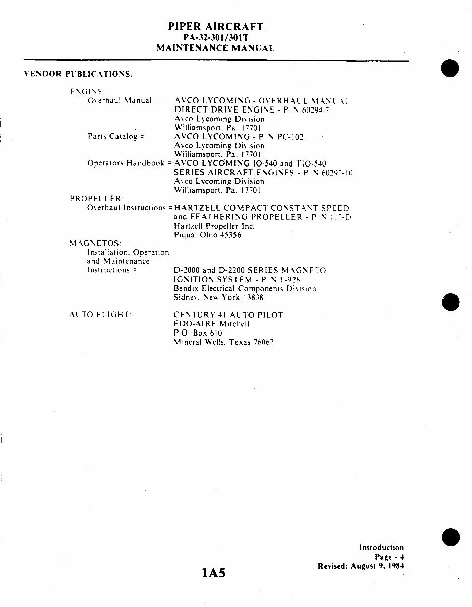
VENDOR PUBLICATIONS.
ENGINE
Overhaul Manual = AVCO LYCOMING - OVERHAUL MAL AL
DIRECT DRIVE ENGINE - P \ 60294--
Axco Lycoming Dixision
Williamsport. Pa. 17701
Parts Catalog = AVCO LYCOMING - P N PC-102
Axco Lvcoming Dixision
Williamsport. Pa. 17701
Operators Handbook = AVCO LYCOMING 10-540 and TIO-540
SERIES AIRCRAFT ENGINES - P N 60297-10
Avco Lycoming Division
Williamsport. Pa. 17701
PROPELIER:
Overhaul Instructions =HARTZELL COMPACT CONSTANT SPEED
and FEATHERING PROPELLER - P N I -- D
Hartzell Propeller Inc.
Piqua. Ohio 45356
MAGN ETOS:
Installation. Operation
and Maintenance
Instructions =
AUTO FL.IGHT:
D-2000 and D-2200 SERIES MAGNETO
IGNITION SYSTEM - P N L-928
Bendix Electrical Components Dixision
Sidney. New York 13838
CENTURY 41 AUTO PILOT
EDO-AIRE Mitchell
P.O. Box 610
Mineral Wells. Texas 76067
S
Introduction
Page - 4
Revised: August 9. 1984
IA5
PIPER AIRCRAFT
PA-32-301/301T
MAINTENANCE MANUAL
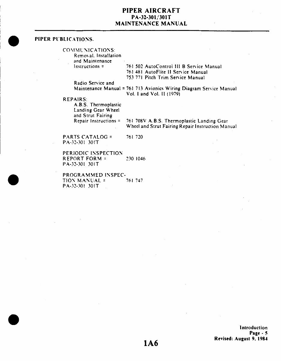
PIPER PUBLICATIONS.
COMMUNICATIONS:
Removal. Installation
and Maintenance
Instructions = 761 502 AutoControl III B Service Manual
761 481 AutoFlite II Service Manual
753 771 Pitch Trim Service Manual
Radio Service and
Maintenance Manual = 761 713 Avionics Wiring Diagram Service Manual
Vol. I and Vol. 11 (1979)
REPAIRS:
A.B.S. Thermoplastic
Landing Gear Wheel
and Strut Fairing
Repair Instructions =761 708V A.B.S. Thermoplastic Landing Gear
Wheel and Strut Fairing Repair Instruction Manual
PARTS CATALOG 761 720
PA-32-301 301T
PERIODIC INSPECTION
REPORT FORM 230 1046
PA-32-301 301T
PROGRAMMED INSPEC-
TION MANUAL= 761 747
PA-32-301 301T
Introduction
Page - 5
Revised: August 9, 1984
1A6
PIPER AIRCRAFT
PA-32-301/301T
MAINTENANCE MANUAL
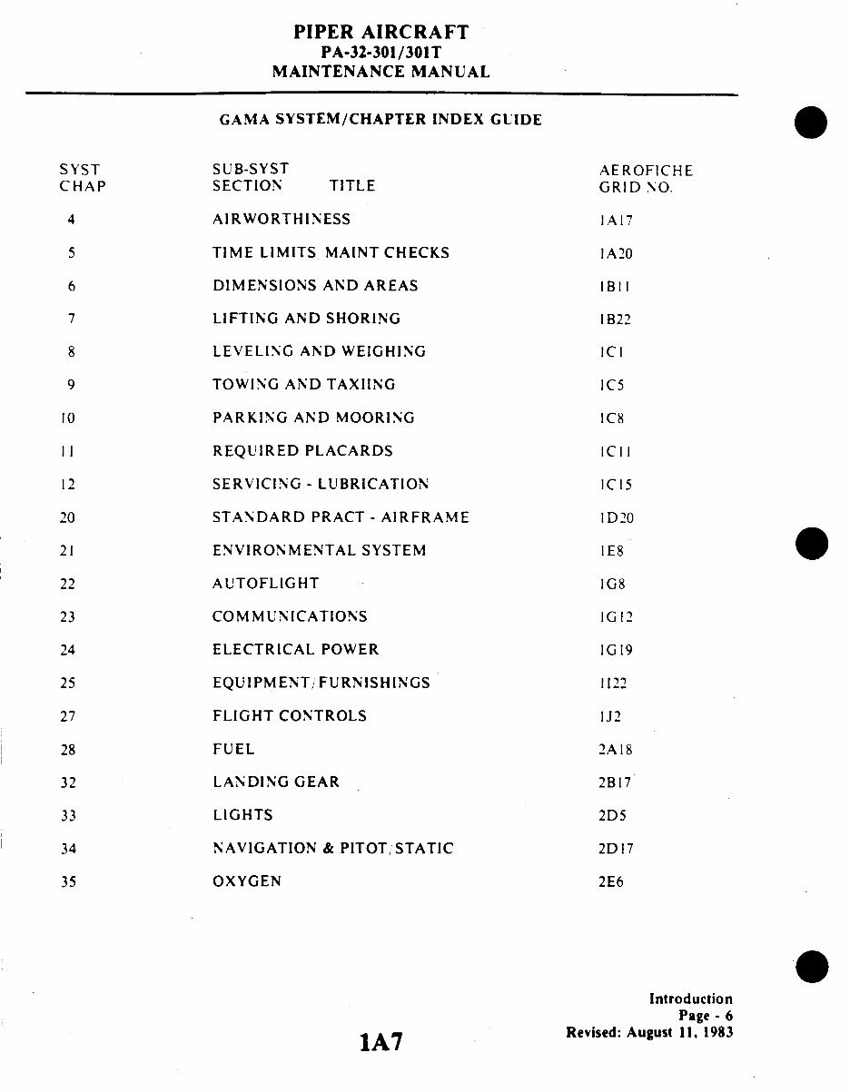
GAMA SYSTEM/CHAPTER INDEX GUIDE
SYST
CHAP
4
5
6
7
8
9
10
II
12
20
21
22
23
24
25
27
28
32
33
34
35
SUB-SYST
SECTION TITLE
AIRWORTHINESS
TIME LIMITS MAINT CHECKS
DIMENSIONS AND AREAS
LIFTING AND SHORING
LEVELING AND WEIGHING
TOWING AND TAXIING
PARKING AND MOORING
REQUIRED PLACARDS
SERVICING - LUBRICATION
STANDARD PRACT - AIRFRAME
ENVIRONMENTAL SYSTEM
ALTOFLIGHT
COMMUNICATIONS
ELECTRICAL POWER
EQUIPMENT/FURNISHINGS
FLIGHT CONTROLS
FUEL
LANDING GEAR
LIGHTS
NAVIGATION & PITOT, STATIC
OXYGEN
AEROFICHE
GRID NO.
1A17
IA20
IBII
I B22
ICI
IC5
IC8
IC11
IC15
ID20
IE8
IG8
IG12
IG19
1122
IJ2
2A18
2B17
2D5
2D17
2E6
Introduction
Page -6
Revised:August 11, 1983
1A7
PIPER AIRCRAFT
PA-32-301/301T
MAINTENANCE MANUAL
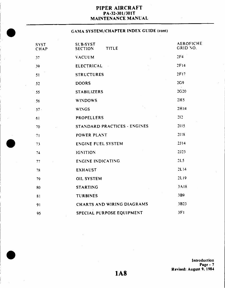
GAMA SYSTEM/CHAPTER INDEX GUIDE (cont)
SYST
CHAP
37
39
51
52
55
56
57
61
70
71
73
74
77
78
79
80
81
91
95
SUB-SYST
SECTION TITLE
VACUUM
ELECTRICAL
STRUCTURES
DOORS
STABILIZERS
WINDOWS
WINGS
PROPELLERS
STANDARD PRACTICES - ENGINES
POWER PLANT
ENGINE FUEL SYSTEM
IGNITION
ENGINE INDICATING
EXHAUST
OIL SYSTEM
STARTING
TURBINES
CHARTS AND WIRING DIAGRAMS
SPECIAL PURPOSE EQUIPMENT
AEROFICHE
GRID NO.
2F4
2F14
2F17
2G9
2G20
2H5
2H14
212
2115
2118
2J14
2J23
2L5
2L14
2L19
3A18
3B9
3B23
3FI
Introduction
Page- 7
Revised: August9. 1984
1A8
PIPER AIRCRAFT
PA-32-301/301T
MAINTENANCE MANUAL
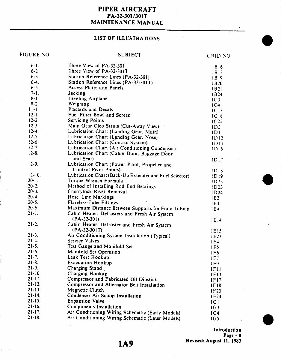
LIST OF ILLUSTRATIONS
FIGURE NO.
SUBJECT
GRID NO.
6-1.
Three View of PA-32-301
1B16
6-2.
Three View of PA-32-301T
1B17
6-3.
Station Reference Lines (PA-32-301)
1B19
6-4.
Station Reference Lines (PA-32-301T)
1B20
6-5.
Access Plates and Panels
1B21
7-1. Jacking
1 B24
8-1. Leveling Airplane
1C3
8-2. Weighing
IC4
11 1-. Placards and Decals
1C13
12-1.
Fuel Filter Bowl and Screen
1C18
12-2. Servicing Points
IC22
12-3.
Main Gear Oleo Struts (Cut-Away View)
1D2
12-4.
Lubrication Chart (Landing Gear, Main)
1DII
12-5.
Lubrication Chart (Landing Gear, Nose) ID12
12-6.
Lubrication Chart (Control System)
ID13
12-7.
Lubrication Chart (Air Conditioning Condenser)
I D16
12-8.
Lubrication Chart (Cabin Door, Baggage Door
and Seat)
ID17
12-9.
Lubrication Chart (Power Plant, Propeller and
Control Pivot Points)
1D18
12-10.
Lubrication Chart (Back-Up Extender and Fuel Selector) ID19
20-1.
Torque Wrench Formula
1D23
20-2.
Method of Installing Rod End Bearings
1D23
20-3.
Cherrylock Rivet Removal
1D24
20-4.
Hose Line Markings
IE2
20-5.
Flareless-Tube Fittings
IE3
20-6.
Maximum Distance Between Supports for Fluid Tubing IE4
21-1.
Cabin Heater. Defrosters and Fresh Air System
(PA-32-301)
I E 14
21-2.
Cabin Heater. Defroster and Fresh Air System
(PA-32-301T)
1E 15
21-3.
Air Conditioning System Installation (Typical) 1E23
21-4. Service Valves
1F4
21-5.
Test Gauge and Manifold Set
1F5
21-6.
Manifold Set Operation
1F6
21-7. Leak Test Hookup
1F7
21-8. Evacuation Hookup
1F9
21-9. Charging Stand
IFII
21-10. Charging Hookup
1F13
21-11.
Compressor and Fabricated Oil Dipstick
I F17
21-12.
Compressor and Alternator Belt Installation
1F18
21-13. Magnetic Clutch
1F20
21-14.
Condenser Air Scoop Installation
1F24
21-15. Expansion Valve
1GI
21-16.
Components Installation
1G3
21-17.
Air Conditioning Wiring Schematic (Early Models) 1G4
21-18.
Air Conditioning Wiring Schematic (Later Models)
IG5
Introduction
Page - 8
1A9 Revised: August 11, 1983
PIPER AIRCRAFT
PA-32-301/301T
MAINTENANCE MANUAL
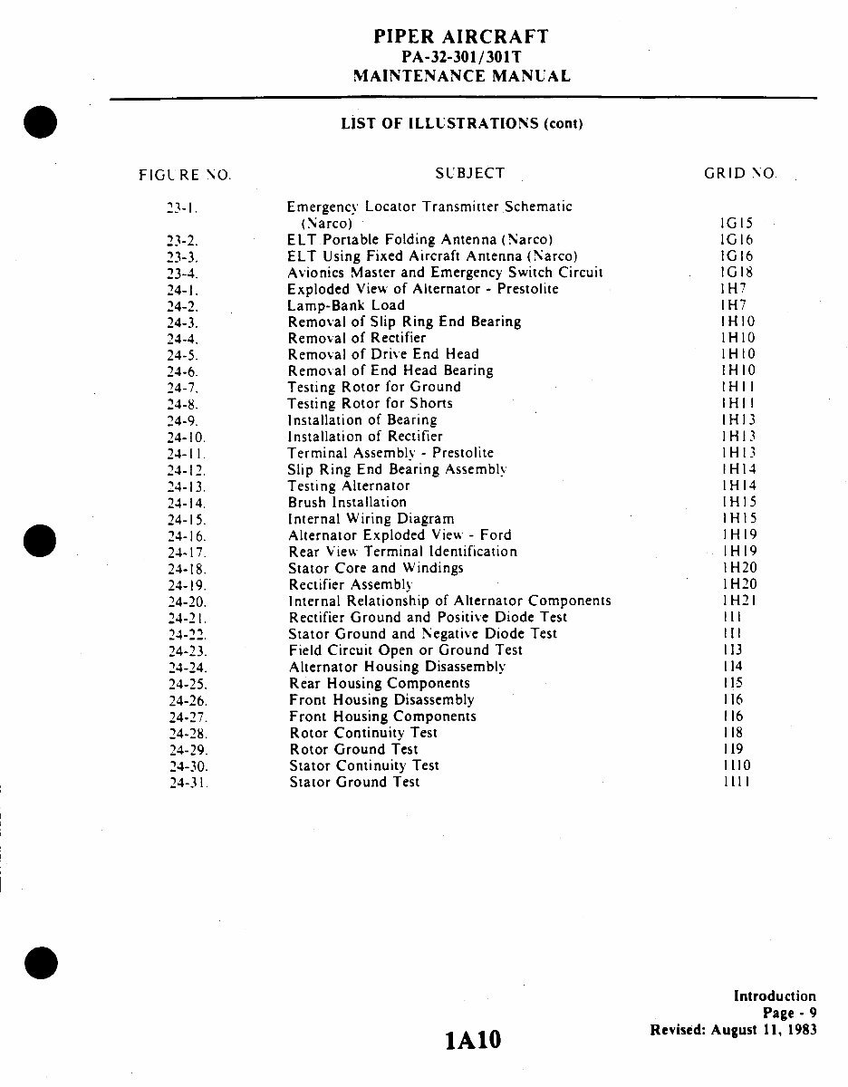
LIST OF ILLUSTRATIONS (cont)
FIGL RE NO. SUBJECT GRID NO
23-1. Emergency Locator Transmitter Schematic
(Narco) IG15
23-2. ELT.Portable Folding Antenna (Narco) IG16
23-3. ELT Using Fixed Aircraft Antenna (Narco) 1G16
23-4. Avionics Master and Emergency Switch Circuit IG18
24-1. Exploded View of Alternator - Prestolite 1H7
24-2. Lamp-Bank Load 1H7
24-3. Removal of Slip Ring End Bearing IHIO
24-4. Removal of Rectifier IHIO
24-5. Removal of Drive End Head IH 10
24-6. Removal of End Head Bearing IH10
24-7. Testing Rotor for Ground IHI 1
24-8. Testing Rotor for Shorts IH11
24-9. Installation of Bearing IH13
24-10. Installation of Rectifier IH13
24-11 . Terminal Assembly - Prestolite IH13
24-12. Slip Ring End Bearing Assembly IH14
24-13. Testing Alternator IH14
24-14. Brush Installation IH15
24-15. Internal Wiring Diagram IH15
24-16. Alternator Exploded View - Ford IH19
24-17. Rear View Terminal Identification 1H19
24-18. Stator Core and Windings IH20
24-19. Rectifier Assembly 1H20
24-20. Internal Relationship of Alternator Components 1H21
24-21. Rectifier Ground and Positive Diode Test II1
24-22. Stator Ground and Negative Diode Test III
24-23. Field Circuit Open or Ground Test 113
24-24. Alternator Housing Disassembly 114
24-25. Rear Housing Components I15
24-26. Front Housing Disassembly 116
24-27. Front Housing Components 116
24-28. Rotor Continuity Test 118
24-29. Rotor Ground Test 119
24-30. Stator Continuity Test 1110
24-31. Stator Ground Test 1111
Introduction
Page - 9
lA10 Revised: August 11, 1983
IAI0
You're Reading a Preview
What's Included?
 Lifetime Access
Fast Download Speeds
Online & Offline Access
Access PDF Contents & Bookmarks
Full Search Facility
Print one or all pages of your manual
$46.99
Piper Saratoga (PA-32-301/301T) Aircraft Maintenance Manual
Viewed 11 Times Today

What's Included?
Lifetime Access
Fast Download Speeds
Online & Offline Access
Access PDF Contents & Bookmarks
Full Search Facility
Print one or all pages of your manual
$46.99

Secure transaction
What's Included?
Lifetime Access
Fast Download Speeds
Online & Offline Access
Access PDF Contents & Bookmarks
Full Search Facility
Print one or all pages of your manual
Description
The Piper Saratoga (PA-32-301/301T) Aircraft Maintenance Manual is a comprehensive guide for maintaining and repairing the Piper Saratoga aircraft models. This manual, with the reference number 761-721 and last revised on August 11, 1983, contains detailed technical information essential for both professional mechanics and DIY enthusiasts.


