

753-704 Piper navajo PA31 service manual PA31-300 / 325
What's Included?
Fast Download Speeds
Online & Offline Access
Access PDF Contents & Bookmarks
Full Search Facility
Print one or all pages of your manual
PIPER
AIRPLANE
SERVICE MANUAL
CARD 1 OF 5
PA-31
PA-31-300
PA-31-325
PIPER AIRCRAFT CORPORATION
(PART NUMBER 753 704)
lAl

PIPER NAVAJO SERVICE MANUAL
AEROFICHE EXPLANATION AND REVISION STATUS
Service manualinformation incorporated in this set of Aerofichecards is arranged in accordance with
general specifications of Aeroficheadoptedby GeneralAviation Manufacturer'sAssociation. Information
compiled in this Aerofiche service manual is kept current by revisions distributed periodically. These
revisions supersede all previous revisions and are complete Aerofichecard replacements and supersede
Aerofichecards of samenumberin set, exceptas notedbelow.
Identification of revised material: Revised text and illustrations are indicatedby a black vertical line
along the left-hand margin of the frame, opposite revised,or added material.Revision lines indicate only
current revisions with changes and additionsto existingtext and illustrations.Changesin capitalization,
spelling, punctuation, indexing.physicallocation of materialor completepage additionsare not identified
by revisionlines.
Revisions to service manual 753 704 issued October 1, 1966 are as follows:
Revisions Publication Date Aerofiche CardEffectivity
ORG661001
CR720707
CR791012
PR800923
PR810311
P R8 10924
PR820129
PR821115
PR831012
PR840302
PR840503
IR860429
IR860921
IR870505
IR871009
IR900313
PR940218
IR941202
October 1, 1966
July 7, 1972
October 12, 1979
September 23, 1980
March 11. 1981
September 24, 1981
January 29, 1982
November 15,1982
October 12, 1983
March 2, 1984
May 3,1984
April 29,1986
September 21, 1986
June 12, 1987
June 15, 1988
Marchl3, 1990
February 18, 1994
December 2, 1994
1, 2, 3,4 and5
1, 2, 3,4 and 5
1, 2, 3,4 and5
1, 2, 3,4 and5
1,2, 3,4 and5
1,2, 3,4and5
1,2, 3,4and5
1,2, 3,4 and5
1
1
1
1
2
1
1, 2, 3,4 and 5
1
INTERIM REVISION
REVISIONS APPEAR IN THE INTRODUCTION AND
SECTION III OF CARD 1. PLEASE DISPOSE OF YOUR
CURRENT CARD 1, AND REPLACE IT WITH THE
REVISED CARD.
Consult the Customer Service Information Aerofiche for current revision dates for this manual.
Revised: February18, 1994
Interim Revision: December 2, 1994
1A2

TABLE OF CONTENTS
AEROFICHE CARD NO. 1 GRID NO.
I
III
IV
V
INTRODUCTION ........................
HANDLING AND SERVICING ...........
INSPECTION ............................
STRUCTURES ...........................
SURFACE CONTROLS ..................
...........
...........
...........
...........
...........
1A17
1A20
1D9
1E11
1H20
AEROFICHE CARD NO. 2
VI
VII
VIII
VIIIA
VIIIB
HYDRAULIC SYSTEM...................
LANDING GEAR AND BRAKE SYSTEM .
POWER PLANT (PA-31 Turbo)...........
POWER PLANT (PA-31-300) ............
POWER PLANT (PA-31-325) ............
...........
...........
...........
...........
...........
2A9
2E4
2H6
2K8
2K18
AEROFICHE CARD NO. 3
IX
X
FUEL SYSTEM ..........................
INSTRUMENTS .........................
...........
...........
3A8
3C21
XI
AEROFICHE CARD NO. 4
ELECTRICAL SYSTEM ..................
AEROFICHE CARD NO. 5
ELECTRONICS ..........................
HEATING AND VENTILATING...........
ACCESSORIES AND UTILITIES .........
4A7
XII
XIII
XIV
5A9
5B3
5E1
1A3
INTENTIONALLY
LEFT BLANK

PIPER NAVAJO SERVICE MANUAL
LIST OF ILLUSTRATIONS
Figure
Aerofiche
Grid No.
2-1. Three-View of Navajo .................. ......... ... ................ 1A23
2-2. Station Reference Lines ..................... .......... ................. . B4
2-3. Access Plates and Panels, Fuselage Interior ................................. 1B7
2-4. Access Plates and Panels. Fuselage and Empennage ................ ............ 1B8
2-5. Access Plates and Panels. Wings ............................................. B9
2-5a. Torque Wrench Formula ........................... ..... .......... ..... 1B13
2-6. Jacking Arrangements ...................................................... 1B14
2-7. Weighing the Airplane ................................................... 1
2-8. Leveling Longitudinally .............................................. IB15
2-9. Leveling Laterally ........................................ ................. 1
2-10. Tow Turn Limits Indicator ........................................ ......... B17
2-11. Service Points ............................................................ 1B19
2-12. Servicing Landing Gear Shock Struts ........................................ IB22
2-12a. Tire Balancer ............................................................. 1C1
2-13. Lubrication Chart (Landing Gear. Main) ............. ........................ 1C10
2-13a. Lubrication Chart (Landing Gear, Nose) .................................... ICII
2-13b. Lubrication Chart (Control System) ..... ......... ................ ............ 1C12
2-13c. Lubrication Chart (Control System) (cont.) ................................... 1C13
2-13d. Lubrication Chart (Power Plant. Propeller and Cowl Flap) ..................... IC14
2-13e. Lubrication Chart (Doors and Seats) ........................................ IC15
2-14. Fabricated Jack Stand for Piper Jack, Part No. 18338-00 ....................... 1C19
2-15. Fabricated Tail Stand ......................... ............................. 1C20
2-16. Removal of Cherrylock Rivets ............................................... IDI
2-17. Identification of Aircraft Fluid Lines .......................................... 1D2
3-1. Wing Flap Transmission Inspection .................... ....................... ID12
3-2. Wing Flap Actuator Cable - 100 Hour Inspection .............................. ID13
3-2a. Wing Flap Actuator Cable - 500 Hour Inspection ............................. ID14
3-3. Friction Reduction in Wing Flap System ................................... ............... 1D18
3-4. Wing Flap Motor.......................................................... 1D19
3-5. Fuel Selector and Crossfeed Valve Control Cables ................... .......... ID21
3-6. Inspection of Aileron Sprocket and Chain .................................... 1D22
4-1. Landing Light ............... .................................... .......... IE16
4-2. Aileron and Flap Installation ................................................ 1
4-3. Methods of Blocking Trim Cables ...........................................
1
4-4. Fuselage Cradle ...........................................................
1
4-5. Wing Installation .......................................................... 1
4-6. Empennage Installation .....................................................
1F3
4-7 Windshield Installation (Standard) ........................................... IFII
4-8. Windshield Installation (Heated) ............................................. 1
4-9. Windshield Wiper ........................................................
IF15
4-10. Side Window Installation (Typical) ......................................... IF17
4-11. Cabin Entrance Door Latch Assembly ....................................... 1
4-12. Nacelle Wing Lockers ...................................................... 1F23
Revised: 3/2/84
1A5
PIPER NAVAJO SERVICE MANUAL
LIST OF ILLUSTRATIONS
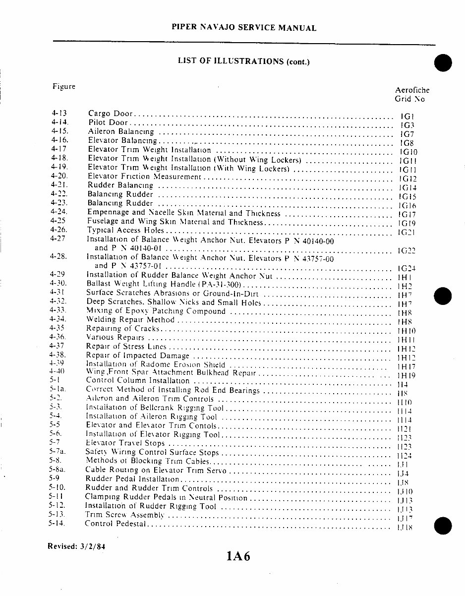
(cont.)
Figure
Aerofiche
Grid No
4-13 Cargo Door.................................................
IGI
4-14. Pilot Door.......... ...............................................
1G
4-15. Aileron Balancing.1G7
4-15. Aileron Balancing ......................................................... IG7
4-16. Elevator Balancing .... ............................................
1G8
4-17 Elevator Trim Weight Installation ............................................
IG10
4-18. Elevator Trim Weight Installation (Without Wing Lockers) .................. .. .. 1G11
4-19. Elevator Trim Weight Installation
(With Wing Lockers) .........................
IGII
4-20. Elevator Friction Measurement.........................................
1G
4-21. Rudder Balancing.1G14
4-1. Rudder Balancing .........................................................
1G14
4-22. Balancing Rudder ..........................................................
1G15
4-23. Balancing Rudder .......................................................
IG16
4-24. Empennage
and Nacelle Skin Material and Thickness ...........................
1G17
4-25
Fuselage and Wing Skin Material and Thickness ...............................
1G19
4-26. Typical Access Holes .........
1G
4-27 Installation of Balance Weight Anchor Nut. Elevators P N 40140-00
and P N 40140-01
1G22 and P N 40140-01 ........................................................
1G22
4-28. Installation of Balance Weight Anchor Nut. Elevators P N 43757-00
and P N 43757-01 ..........................................
1G24
4-29 Installation of Rudder
Balance Weight Anchor Nut .............................
1H1
4-30.
Ballast Weight Lifting Handle (PA-31-300) .....................................
1H2
4-31 Surface Scratches Abrasions or Ground-In-Dirt ...................... .... 1H7
4-32. Deep Scratches. Shallow
Nicks and Small Holes ...............
1H
4-33.
Mixing of Epoxy Patching Compound .......................................
1H8
4-34. Welding Repair Method..............................
1H8
4-35 Repairing of Cracks.... ..... .. 1H10.. ...........
1
4-36. Various Repairs ................ 1H11
4-37 Repair of Stress Lines ................
1
4-38. Repair of Impacted Damage .................................................
1
4-39 Installation of Radome Erosion Shield .......................
H 17
4-40 Wing,Front Spar Attachment Bulkhead Repair ................................
1H
5-1 Control Column Installation .......................................
114
5-1a. Correct Method of Installing Rod End Bearings ................................
5-2. Ailcron and Aileron Trim Controls ...........
5-3. Installation of Bellcrank R in Tool.......................................
1114
5-4. Installation of Aileron Rigging Tool ..................................
. . 111
5-5 Elevator and Eleator Trim Contols...........................................
1121
5-6. Installation of Elevator Rigging Tool .......................................
5-7 Elevator Travel Stops .......................................
.
11
5-
7
a. Safety Wiring Control Surface Stops ...................................
. 1124
5-8. Methods
of Blocking Trim Cables ..............
1
5-8a. Cable Routing on Elevator Trim Sero ...............................
1J4
5-9 Rudder Pedal Installation ...............................................
....
5-10.
Rudder and Rudder Trim Controls ........................................
1
5-11 Clamping Rudder Pedals in Neutral Position ...................................
1J13
5-12. Installation of Rudder Rigging Tool
5-12. Installation of Rudder Rigging Tool .......................................... 1G13
5-13. Trim Screw Assembly 5-13. Trim Screw Assembly .......................................................
1J13
5-14. Control Pedestal.............
1J18
Revised: 3/2/84
1A6

PIPER NAVAJO SERVICE MANUAL
LIST OF ILLUSTRATIONS (cont.)
Figure Aerofiche
Grid No.
5-15.
5-16.
5-17
5-18.
5-19.
5-20.
5-21
5-23.
5-24.
5-25.
5-26.
5-26a.
5-26b
5-27.
5-28.
5-29
6-1
6-2.
6-3.
6-4.
6-5.
6-6.
6-7
6-8.
6-9.
6-10.
6- 11
6-12.
6-13.
6-14.
6-15.
6-16.
6-17
6-18.
6-19
6-20.
6-21.
6-22.
6-23.
6-24.
6-25.
6-26.
6-27.
Flap Controls (Piper System) ................................................
Flap Circuit Schematic (Dukes System)........................................
Flap Rigging Check ........................................................
Flap System Diagram (Calco) ................................................
Motor Assembly. Exploded View .............................................
Flap Controls (Calco System) ................................................
Deleted ...................................................................
Deleted ...................................................................
Deleted . . . ...........................................
Deleted ...................................................... ............
Flap Rigging Adjustments ...................................................
Use of Flap Rigging Tool ....................................................
Amplifier - Electrical Schematic (Calco) P N 8482 .............................
Amplifier - Electrical Schematic (Calco) P N 8502M I ..........................
IJ20
IJ24
IKI
IK3
IK5
IK8
IK16
1K16
1KI8
1K21
1L 15
Fabricated Bellcrank Rigging Tool ..........................
Fabricated Aileron - Elevator Rigging Tool ..................
Fabricated Rudder Rigging Tool ...........................
Schematic Diagram of Hydraulic System (Ozone 2930-1) ......
Schematic Diagram of Hydraulic System (Ozone 2930-3) ......
Schematic Diagram of Hydraulic System (Ozone 2930-5 and -7)
or (Wiebel 2135-1 and -3)................................
Schematic of Power Pack Electrical S\stem ..................
Power Pack Installation (Ozone 2930-1) .....................
Power Pack Installation (Ozone 2930-3) .....................
Power Pack Installation (Ozone 2930-5 and -7) or (Wiebel 2135-
Identification of Power Pack ...............................
Location of Power Pack Components (Ozone) ................
Hydraulic Power Pack (Ozone 2930-1) ......................
Hydraulic Power Pack (Ozone 2930-3. -5 and -7) .............
Power Pack Manifold (Ozone) .............................
Power Pack Handle Release (Ozone) ....... ................
Safetying Control Arms (Ozone) ............................
Timing of Selector Spool (Ozone). ..........................
Handle Release Adjustment (Ozone) ........................
Location of Power Pack Components (Wiebel Tool) ..........
Hydraulic Power Pack (Wiebel Tool). .................
Power Pack Manifold (Wiebel Tool) ........................
Power Pack Handle-Release Mechanism (Wiebel Tool) ........
Safetying Control Arm (Wiebel Tool) ......................
Indexing of Selector Spool (Wiebel Tool) ....................
Handle Release Adjustment (Wiebel Tool) ...................
Landing Gear Selector Mechanism. Serial Nos. 31-5 thru 31-511
Landing Gear Selector Mechanism. Serial Nos. 31-512 and up..
Hand Pump (Ozone)......................................
Hand Pump (Wiebel Tool) .................................
.................
. . .. .. ...
. . . . . . . .
. . .. .. ...
. . .. .. ...
..........
..................
. . . . . . . . . . . . . . . . .
...................
..............
...................
. . . . . . . . . . . . . . . . . .
...................
...................
..................
. . . . . . . . . . . . . . . . .
. . . . . . . . . . . . . . . . .
11.16
1l.17
2A17
2A18
2A19
2A20
2A21
2A22
2A23
2B13
2B16
2B21
2B22
2Cl
2C1
2C4
2C9
2C I
2C14
2C15
2C17
2C21
2C 24
2D2
2D5
Revised: 3/2/84
1A7
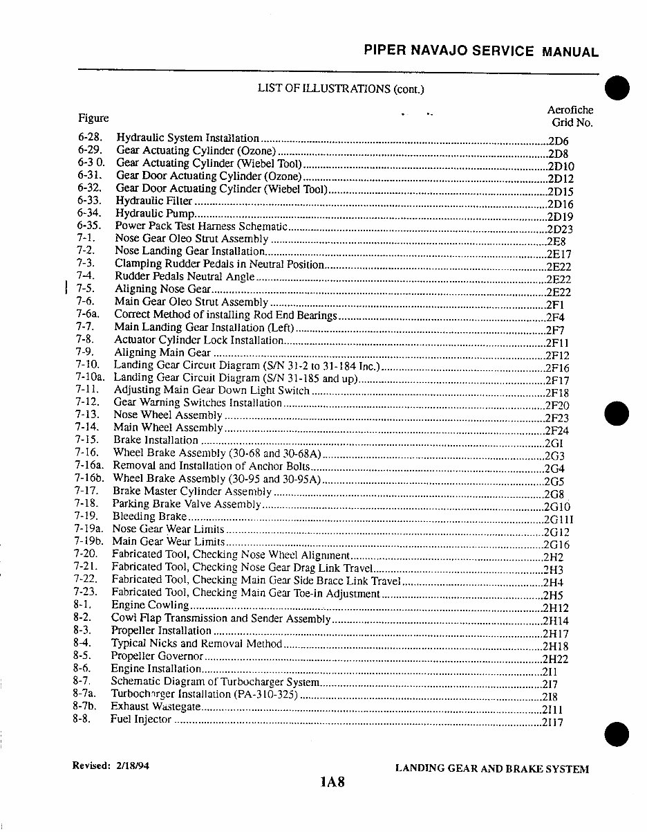
PIPER NAVAJO SERVICE MANUAL
LIST OF ILLUSTRATIONS
(cont.)
Aerofiche
Figure
Grid No.
6-28.
Hydraulic System Installation ........ ......................................................
2D6
6-29.
Gear Actuating Cylinder (Ozone) ........................................................................................
2D8
6-3 0.
Gear Actuating Cylinder (Wiebel Tool)...............................................................2D10
6-31.
Gear Door Actuating Cylinder (Ozone) ....... ..........................................
2D12
6-32.
Gear Door Actuating Cylinder (Wiebel Tool)......................................................15
6-33. Hydraulic Filter .......................................................................................
2D16
6-34. Hydraulic Pum p..............................................................................................................
2D19
6-35.
Power Pack Test Harness Schematic.....................................................................................
2D23
7-1.
Nose Gear Oleo Strut Assembly ........ ...........................................................
E8
7-2. Nose Landing Gear Installation...........................................
................................ 2E17
7-3.
Clamping Rudder Pedals in Neutral Position.............................................................................2E22
7-4.
Rudder Pedals Neutral Angle ....................................................................................
2E22
7-5. Aligning Nose Gear. .............................................
2E22
7-6.
Main Gear Oleo Strut Assembly ................................................................................................
2F
7-6a.
Correct Method of installing Rod End Bearings............ ...............................................
2F4
7-7.
Main Landing Gear Installation (Left) ............................................................................
2F7
7-8.
Actuator Cylinder Lock Installation...........................................................................................
2F
7-9. Aligning Main Gear .......... ...............................................................................................
2F12
7-10.
Landing Gear Circuit Diagram (S/N 31-2 to 31-184 Inc.) ...........................................
2F16
7-10a.
Landing Gear Circuit Diagram (S/N 31-185 and up) .............................................
2F17
7-11.
Adjusting Main Gear Down Light Switch ............................................................................
2F18
7-12.
Gear Warning Switches Installation...........................................
................. 2F20
7-13. Nose W heel Assembly ................................................................
7-14. Main W heel Asse m bly.....................................................................................2F24
7-15. Brake Installation ..................................................................................................
2G
7-16.
W heel Brake Assembly (30-68 and 30-68A)...........................................
........ ... 2G3
7-16a.
Removal and Installation of Anchor Bolts...............................................................................2G4
7-16b. Wheel Brake Assembly (30-95 and 30-95A ......................................
2G5
7-17.
Brake Master Cylinder Assembly ..............................................................................................
2G8
7-18.
Parking Brake Valve Assembly ...........................................................................................
2G10
7-19. Bleeding Brake ................... ...........................................................................
2G I
7-19a. Nose Gear Wear Limits .. . ......................................................................
2G12
7-19b. Main Gear Wear Limits ............................................................................................
2G16
7-20.
Fabricated Tool, Checking Nose Wheel Alignment ...............................................
2H2
7-21.
Fabricated Tool, Checking Nose Gear Drag Link Travel .............................................. 2H3
7-22.
Fabricated Tool, Checking Main Gear Side Brace Link Travel ...............................................
2H4
7-23.
Fabricated Tool, Checking Main Gear Toe-in Adjustment ...............................................
2H5
8-1. Engine Cowling ........................................................................................................
12
8-2.
Cowl Flap Transmission and Sender Assembly.....................................................................
2H14
8-3. Propeller Installation .........................................................................................................
2H17
8-4.
Typical Nicks and Removal Method ...........................................................................
2H18
8-5. Propeller Governor ...................................................................................................
2H22
8-6. Engine Installation.......................................................................................211
8-7.
Schematic Diagram of Turbocharger System...............................................
................. 217
8-7a.
Turbocharger Installation (PA-310-325) ....... .............................................
218
8-7b. Exhaust W tegate....................................................................................................................2I11
8-8. Fuel Injector ...............................................................................................................................
2117
Revised: 2/18/94
LANDING GEAR AND BRAKE SYSTEM
1A8
PIPER NAVAJO SERVICE MANUAL
LIST OF ILLUSTRATIONS (cont.)
Figure
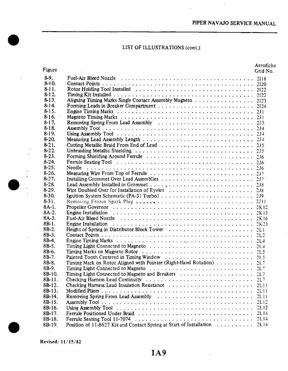
8-9.
8-10.
8-11.
8-12.
8-13.
8-14.
8-15.
8-16.
8-17.
8-18.
8-19.
8-20.
8-21.
8-22.
8-23.
8-24.
8-25.
8-26.
8-27.
8-28.
8-29.
8-30.
8-31.
8A-1.
8A-2.
8A-3.
8B-1.
8B-2.
8B-3.
8B-4.
8B-5.
8B-6.
8B-7.
8B-8.
8B-9.
8B-10.
8B-11.
8B-12.
8B-13.
8B-14.
8B-15.
8B-16.
8B-17.
8B-18.
Fuel-Air Bleed Nozzle ....................
Contact Points .........................
Rotor Holding Tool Installed ................
Timing Kit Installed ......................
Aligning Timing Marks Single Contact Assembly Magneto
Forming Leads in Breaker Compartment ..........
Engine Timing Marks .....................
Magneto Timing Marks ....................
Removing Spring From Lead Assembly ..........
Assembly Tool .........................
Using Assembly Tool .....................
Measuring Lead Assembly Length ..............
Cutting Metallic Braid From End of Lead .........
Unbraiding Metallic Shielding ................
Forming Shielding Around Ferrule .............
Ferrule Seating Tool .....................
Needle . .. ... . .............. . ......
Measuring Wire From Top of Ferrule ............
Installing Grommet Over Lead Assemblies .........
Lead Assembly Installed in Grommet ..... ......
Wire Doubled Over for Installation of Eyelet .......
Ignition System Schematic (PA-31 Turbo) .........
Removing Frozen Spark Plug ................
Propeller Governor ......................
Engine Installation ......................
Fuel-Air Bleed Nozzle ....................
Engine Installation ......................
Height of Spring in Distributor Block Tower .......
Contact Points .........................
Engine Timing Marks ......................
Timing Light Connected to Magneto ............
Timing Marks on Magneto Rotor .......
Painted Tooth Centered in Timing Window ........
Timing Mark on Rotor Aligned with Pointer (Right-Hand Rotation)
Timing Light Connected to Magneto ............
Timing Light Connected to Magneto and Breakers ....
Checking Harness Lead Continuity .............
Checking Harness Lead Insulation Resistance .......
Modified Pliers .........................
Removing Spring From Lead Assembly ..........
Assembly Tool .........................
Using Assembly Tool .....................
Ferrule Positioned Under Braid ...............
Ferrule Seating Tool 11-7074 ................
Rotation)
Aerofiche
Grid No.
......... ...... 2118
............... 2120
............... 2122
.......... ..... 2122
.......... .... . 2I23
. ...... ... .. . .. 2124
. ... .. . .. . . . . .. 2Jl
. ..... . ... ... .. 2J1
... ............ 2J3
. ... .. . .. . . . . .. 2J4
. ..... . ... .. . . .2J4
............... 2J4
. ... ... ... ... .. 2J5
............... 2J5
. .. . ... ... .. . . . 2J6
............... 2 J6
. .. . . . . .. . . . . . . 2J6
. .. . ... ... .. . . . 2J7
. .. . ... ... .. . . .2J7
. .. . ... .. . . . . . . 2J8
. .. . ... . .. .. . . . 2J8
.... ........... 2J9
............... 2J1l
. ............ .. 2K12
. ...... ... ..... 2K 13
. ......... ..... 2K 16
............... 2K23
.......... . . ... 2L1
............... 2L2
...... ....... . . 2L4
...... ......... 2L4
. .. . . . . .. . . . . . . 2L5
. . . . .. . .. . . . . . . 2L5
otation) .......... 2L7
............... 2L7
. . . .. .. . ..... . . 2L7
... ... ......... 2L7
............... 2L11
............... 2L II
. .. ... ......... 2L11
. ... ... ... ... . . .2L12
............... 2L14
. .. . ... ... ..... 2L 14
8B-19. Position of 11-8627 Kit and Contact Spring at Start of Installation .. 2L14
Revised: 11/15/82
1A9

PIPER NAVAJO SERVICE MANUAL
LIST OF ILLUSTRATIONS (cont.)
Figure
Aerofiche
Grid No.
8B-20.
Position of 11-8627 Kit and Contact Spring After Installation ................... 2L14
8B-21. Lubricating Sleeve .......................... ............................... 2L15
8B-22. Lubricating Ferrule Shoulder . ..............................................
2L15
8B-23.
Ignition System Schematic (PA-31-325) .......................................
2L17
9-1. Fuel System Schematic (PA-31-310) .. .......................................
3A11
9-la. Fuel System Schematic (PA-31-300) . ........................................
3A12
9-lb. Fuel System Schematic (PA-31-325) ...................... ................... 3A13
9-1c.
Fuel Boost Pump Installation (PA-31-325) .................. ............................... 3A15
9-1d.
Fuel Cell Installation (Nacelle Optional) PA-31-325 only ........ ............ 3A16
9-2.
Fuel Cell Installation (Main Inboard) ........................................
3A21
9-3.
Fuel Cell Installation (Auxiliary Outboard) ..............................
3A22
9-4.
Installation of Fuel Valve Drain Plate ........................................
3A24
9-5. Fuel Gauge Adjustment Wires ...............................................
3B3
9-6. Scott Fuel Selector Valve ...................................................
3B12
9-7. Crossfeed Valve ...........................................................
3B13
9-8. Emergency Shut-Off Valve ..................................................
3B15
9-9.
Fuel System Installation (PA-31 Turbo) ............................. ......... 3B16
9-9a.
Fuel System Installation (PA-31-300) ........................... ................. 3B18
9-10.
Adjustment of Crossfeed %alve ..............................................
3B20
9-1 1. Fuel Filter ................................................................
3B22
9-12.
Electric Fuel Pump (PA-31-310 and -325) ......... .................. 3C2
9-12a. Electric Fuel Pump (PA-31-300) .............................................
3C6
9-13. Fuel Cell Tie Detail ........................................................
3C11
9-14.
Low Fuel Warning Sender Sealing ...........................................
3C12
10-1. Instrument Panel (Typical) ..................................................
3C23
10-2.
Instrument Air System Installation (Typical) .............. ................ 3D2
10-2a.
Single Attitude and Directional Gyro Installation .............................. 3D7
10-3.
Dual Attitude and Directional Gyro Installation ....................... ........ 3D8
10-4.
Single or Dual Attitude and Directional Gyro Installation with
Deicer Boots ............................................................
3D10
10-5. Test Take-Off .............................................................
3D 14
10-6.
Single or Dual Attitude and Directional Gyro Installation with
H-14 Autopilot ..........................................................
3D15
10-7 Pneumatic Relay ..........................................................
3D17
10-8.
Single or Dual Attitude and Directional Gyro Installation with
Deicer Boots and H-14 Autopilot ..........................................
3D19
10-9. Digital Clock .............................................................
3D22
11-1. Overhead Switch Panel .....................................................
4A17
11-2.
Switch and Circuit Breaker Control Panel ....................................
4A18
11-3.
Dual Alternator Wiring System (Delco-Remy) .................................
4A23
11-4.
Cross-Sectional View of Alternator ..........................................
4B2
Revised: 9/24/81
lA10
You're Reading a Preview
What's Included?
Fast Download Speeds
Online & Offline Access
Access PDF Contents & Bookmarks
Full Search Facility
Print one or all pages of your manual
$52.99
Viewed 90 Times Today


Secure transaction
What's Included?
Fast Download Speeds
Online & Offline Access
Access PDF Contents & Bookmarks
Full Search Facility
Print one or all pages of your manual
$52.99
The Piper Navajo PA31 service manual for PA31-300/325 is a comprehensive resource spanning over 1100 pages. It provides detailed instructions for maintenance, repair, and troubleshooting of the aircraft. The manual is designed to be easily navigable, with bookmarked and indexed sections, making it convenient for both professional mechanics and DIY enthusiasts to locate specific information. Whether you prefer to print the entire manual or select sections as needed, this resource offers valuable support for maintaining and servicing the Piper Navajo PA31 aircraft.


