Piper Cherokee PA-24 Aircrafts OEM Service & Repair Manual
What's Included?
Lifetime Access
Fast Download Speeds
Online & Offline Access
Access PDF Contents & Bookmarks
Full Search Facility
Print one or all pages of your manual
CHEROKEE SERVICE MANUAL CARD 1 OF 4 PA-28-140 PA-28-150 PA-28-160 PA-28-180 PA-28-235 PA-28R-180 PA-28R-200 PIPER AIRCRAFT CORPORATION lA1 (PART NUMBER 753 586)
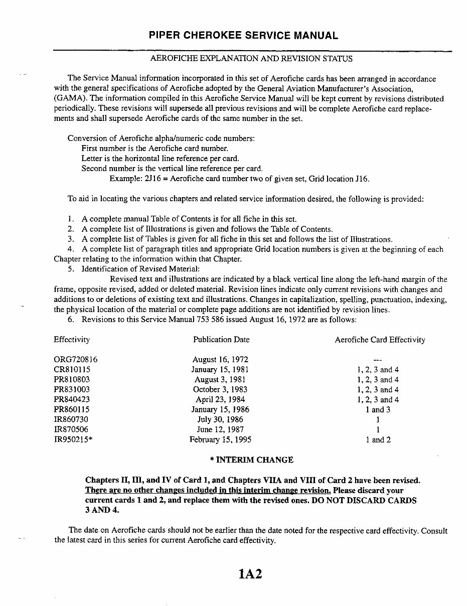
PIPER CHEROKEE SERVICE MANUAL AEROFICHE EXPLANATION AND REVISION STATUS The Service Manual information incorporated in this set of Aerofiche cards has been arranged in accordance with the general specifications of Aerofiche adopted by the General Aviation Manufacturer's Association, (GAMA). The information compiled in this Aerofiche Service Manual will be kept current by revisions distributed periodically. These revisions will supersede all previous revisions and will be complete Aerofiche card replace- ments and shall supersede Aerofiche cards of the same number in the set. Conversion of Aerofiche alpha/numeric code numbers: First number is the Aerofiche card number. Letter is the horizontal line reference per card. Second number is the vertical line reference per card. Example: 2J16 = Aerofiche card number two of given set, Grid location J16. To aid in locating the various chapters and related service information desired, the following is provided: 1. A complete manual Table of Contents is for all fiche in this set. 2. A complete list of Illustrations is given and follows the Table of Contents. 3. A complete list of Tables is given for all fiche in this set and follows the list of Illustrations. 4. A complete list of paragraph titles and appropriate Grid location numbers is given at the beginning of each Chapter relating to the information within that Chapter. 5. Identification of Revised Material: Revised text and illustrations are indicated by a black vertical line along the left-hand margin of the frame, opposite revised, added or deleted material. Revision lines indicate only current revisions with changes and additions to or deletions of existing text and illustrations. Changes in capitalization, spelling, punctuation, indexing, the physical location of the material or complete page additions are not identified by revision lines. 6. Revisions to this Service Manual 753 586 issued August 16, 1972 are as follows: Effectivity Publication Date Aerofiche Card Effectivity ORG720816 August 16, 1972 --- CR810115 January 15, 1981 1,2, 3 and 4 PR810803 August 3, 1981 1, 2, 3 and 4 PR831003 October 3, 1983 1, 2, 3 and 4 PR840423 April 23, 1984 1, 2, 3 and 4 PR860115 January 15, 1986 1 and 3 IR860730 July 30, 1986 1 IR870506 June 12, 1987 1 IR950215* February 15, 1995 1 and 2 * INTERIM CHANGE Chapters II, III, and IV of Card 1, and Chapters VIIA and VIII of Card 2 have been revised. There are no other changes included in this interim change revision. Please discard your current cards 1 and 2, and replace them with the revised ones. DO NOT DISCARD CARDS 3 AND 4. The date on Aerofiche cards should not be earlier than the date noted for the respective card effectivity. Consult the latest card in this series for current Aerofiche card effectivity. 1A2
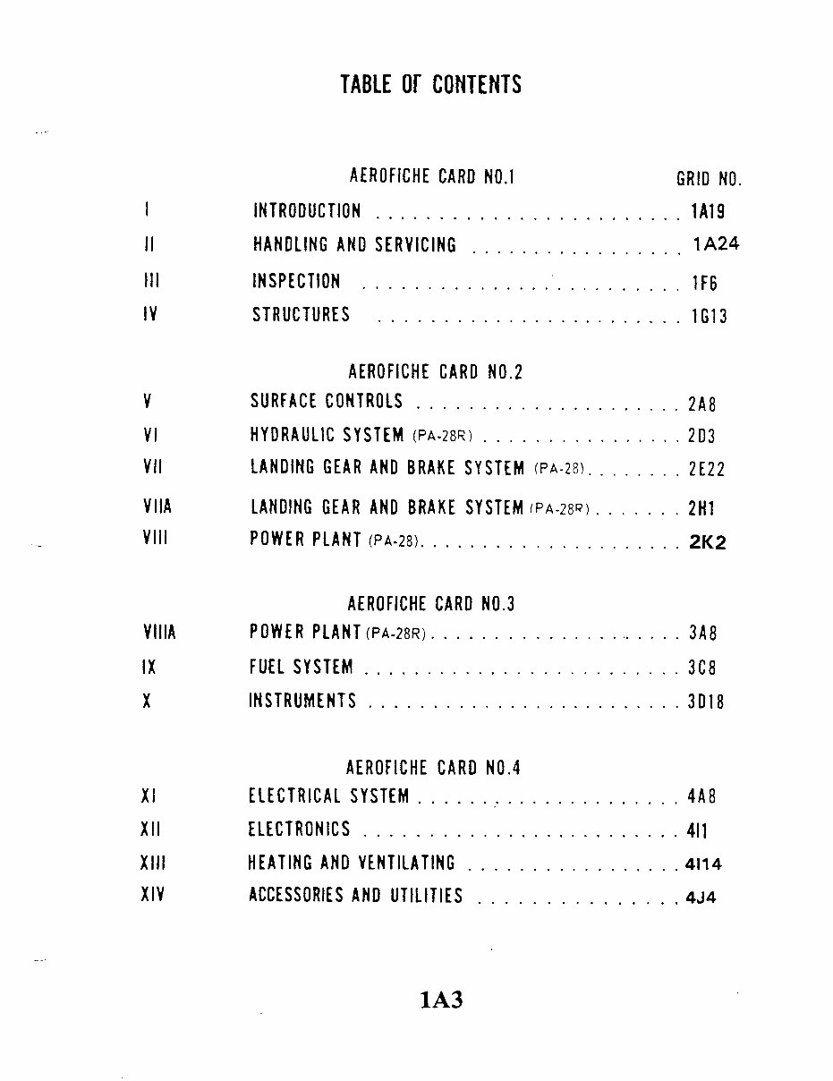
INTRODUCTION HANDLING INSPECTION TABLE OF CONTENTS AEROFICHE CARD NO. 1 INTRODUCTION ............... STRUCTURES V........................ 2A8 VI...... . ........ (PA-28R) LANDING GEAR AND VIIA VIII POWER PLANT (PA-28R) VIIIA . ........ ... IX . XI XIII XIV AEROFACE CARD NO.3 PLANT (PA-28R) AEROFACE CARD NO. NI ACCESSORIES AND UTILITIES 1A3 AIX IIIX 1A24 IX X 2A8 VIIIA 2K2 VIIA IIA IA A Al 4A8 II I
1A4 INTENTIONALLYLEFT BLANK
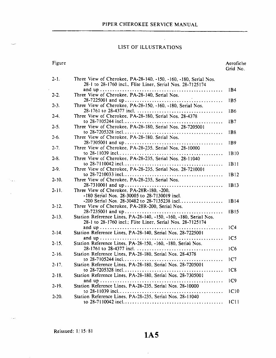
PIPER CHEROKEE SERVICE MANUAL LIST OF ILLUSTRATIONS Figure Aerofiche Grid No. 2-1. Three View of Cherokee, PA-28-140. -150, -160, -180, Serial Nos. 28-1 to 28-1760 incl., Flite Liner, Serial Nos. 28-7125174 and up............................ ...................... B4 2-2. Three View of Cherokee, PA-28-140, Serial Nos. 28-7225001 and up ...... ... ......... ............. B5 2-3. Three View of Cherokee, PA-28-150. -160. -180, Serial Nos. 28-1761 to 28-4377 incl ............... ......... ...... 1B6 2-4. Three View of Cherokee. PA-28-180, Serial Nos. 28-4378 to 28-7105244 inc .............. ............... lB7 2-5. Three View of Cherokee. PA-28-180, Serial Nos. 28-7205001 to 28-7205328 incl ......................................... B8 2-6. Three View of Cherokee. PA-28-180. Serial Nos. 28-7305001 and up ........................................ 1B9 2-7. Three View of Cherokee, PA-28-235. Serial Nos. 28-10000 to 28-11039 incl ..................... .. ...... ............ 1B10 2-8. Three View of Cherokee, PA-28-235. Serial Nos. 28-11040 to 28-7110042 incl......................................... 1B11 2-9. Three View of Cherokee, PA-28-235. Serial Nos. 28-7210001 to 28-7210033 incl ......................................... 1B12 2-10. Three View of Cherokee, PA-28-235. Serial Nos. 28-7310001 and up ........................................ IB13 2-11. Three View of Cherokee. PA-28R-180, -200, -180 Serial Nos. 28-30005 to 28-7130019 incl. -200 Serial Nos. 28-30482 to 28-7135238 incl ............... 1B14 2-12. Three View of Cherokee, PA-28R-200, Serial Nos. 28-7235001 and up .......... .... ............ ......... IB15 2-13. Station Reference Lines. PA-28-140. -150, -160, -180. Serial Nos. 28-1 to 28-1760 incl.: Flite Liner. Serial Nos. 28-7125174 and up .................................................. C4 2-14. Station Reference Lines. PA-28-140, Serial Nos. 28-7225001 and up .................................................. IC 2-15. Station Reference Lines, PA-28-150, -160. -180, Serial Nos. 28-1761 to 28-4377 incl .................................. C6 2-16. Station Reference Lines, PA-28-180. Serial Nos. 28-4378 to 28-7105244 incl ....................................... IC7 2-17. Station Reference Lines. PA-28-180. Serial Nos. 28-7205001 to 28-7205328 incl ........................................ IC8 2-18. Station Reference Lines. PA-28-180, Serial Nos. 28-7305001 and up. IC9 2-19. Station Reference Lines. PA-28-235. Serial Nos. 28-10000 to 28-11039 incl .......... ............................ 1C10 2-20. Station Reference Lines, PA-28-235. Serial Nos. 28-11040 to 28-7110042 incl ........................................ 1C11 Reissued: 1/15/81 1A5 1A5
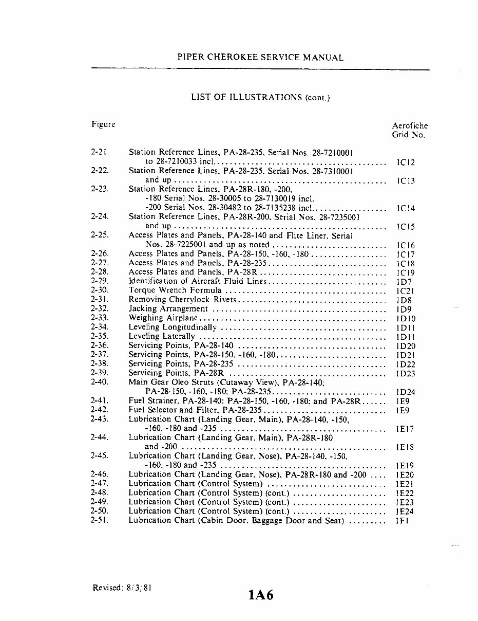
PIPER CHEROKEE SERVICE MANUAL LIST OF ILLUSTRATIONS (cont.) Figure Aerofiche Grid No. 2-21. Station Reference Lines, PA-28-235, Serial Nos. 28-7210001 to 28-7210033 incl ........................................ . 1C12 2-22. Station Reference Lines. PA-28-235, Serial Nos. 28-7310001 and up .................................................. 1C13 2-23. Station Reference Lines, PA-28R-180,-200, -180 Serial Nos. 28-30005 to 28-7130019 incl. -200 Serial Nos. 28-30482 to 28-7135238 incl .................. 1C14 2-24. Station Reference Lines, PA-28R-200, Serial Nos. 28-7235001 and up .................................................. IC15 2-25. Access Plates and Panels, PA-28-140 and Flite Liner. Serial Nos. 28-7225001 and up as noted ........................... 1C16 2-26. Access Plates and Panels, PA-28-150, -160, -180 .... .............. C17 2-27. Access Plates and Panels, PA-28-235 ................. .. ......... C18 2-28. Access Plates and Panels, PA-28R .............................. 1C19 2-29. Identification of Aircraft Fluid Lines ............................ 1D7 2-30. Torque Wrench Formula ...................................... 1C21 2-31. Removing Cherrylock Rivets ................................... 1D8 2-32. Jacking Arrangement ......................................... 1 D9 2-33. Weighing Airplane ............................................. 1D10 2-34. Leveling Longitudinally ....................................... 1 2-35. Leveling Laterally ............................................ 1D11 2-36. Servicing Points, PA-28-140 ................................... 1D20 2-37. Servicing Points, PA-28-150,-160, -180 ....................... 1 2-38. Servicing Points, PA-28-235 ................................... 1D22 2-39. Servicing Points, PA-28R ..................................... 1d23 2-40. Main Gear Oleo Struts (Cutaway View), PA-28-140; PA-28-150,-160,-180; PA-28-235 ........................... 1D24 2-41. Fuel Strainer. PA-28-140; PA-28-150, -160, -180; and PA-28R...... 1E9 2-42. Fuel Selector and Filter, PA-28-235 ............................ 1E9 2-43. Lubrication Chart (Landing Gear, Main), PA-28-140, -150, -160, -180 and -235 ....................................... 1E17 2-44. Lubrication Chart (Landing Gear, Main), PA-28R-180 and -200 ............................................... E18 2-45. Lubrication Chart (Landing Gear, Nose), PA-28-140, -150. -160. -180 and -235 ....................................... 1E19 2-46. Lubrication Chart (Landing Gear, Nose), PA-28R-180 and -200 .... 1 2-47. Lubrication Chart (Control System) ............................ I E21 2-48. Lubrication Chart (Control System) (cont.) ...................... 1E22 2-49. Lubrication Chart (Control System) (cont.) ...................... 1E23 2-50. Lubrication Chart (Control System) (cont.) . ..................... 1 E24 2-51. Lubrication Chart (Cabin Door. Baggage Door and Seat) ......... IF1 Revised: 8/3/81 1A6
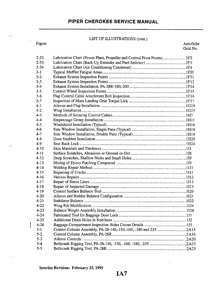
PIPER CHEROKEE SERVICE MANUAL LIST OF ILLUSTRATIONS (cont.) Figure Aerofiche Grid No. 2-52. Lubrication Chart (Power Plant, Propeller and Control Pivot Points) ....................... 1F2 2-53. Lubrication Chart (Back-Up Extender and Fuel Selector) ........................................ 1F3 2-54 Lubrication Chart (Air Conditioning Condenser) ...................................................... F4 3-1 Typical Muffler Fatigue Areas . ................................................... .................... 1F10 3-2 Exhaust System Inspection Points ............................................................................. 1F11 3-3 Exhaust System Inspection Points ............................................................................. F12 3-4 Exhaust System Installation, PA-28R-180,-200 ........................................................IF14 3-5 Control Wheel Inspection Points ...............................................................................1F15 3-6 Flap Control Cable Attachment Bolt Inspection........................................................ 1Fl 6 3-7 Inspection of Main Landing Gear Torque Link ......................................................... 1Fl 7 4-1 Aileron and Flap Installation .................................................................................... 1G19 4-2 Wing Installation ..................................................................... 1G23 4-3 Methods of Securing Control Cables ........................................ .......... 1H7 4-4 Empennage Group Installation ................................................................................. 1H 4-5 Windshield Installation (Typical) ............................... .......................... 1H16 4-6 Side Window Installation, Single Pane (Typical) ...................................................... 1H18 4-7 Side Window Installation, Double Pane (Typical).................................................... 1H18 4-8 Door Snubber Installation . ......................................................... 1H20 4-9 Seat Back Lock ........................................ .................. 1H24 4-10 Skin Materials and Thickness .................................................................................... 1I1 4-11 Surface Scratches, Abrasions or Ground-in-Dirt.......................................................1I8 4-12 Deep Scratches, Shallow Nicks and Small Holes ................... 1................... ............. 119 4-13 Mixing of Epoxy Patching Compound .................................................... 119 4-14 Welding Repair Method ............................................................................................. 4-15 Repairing of Cracks ...................................................................................................1I11 4-16 Various Repairs .......................................................................................................... 1I12 4-17 Repair of Stress Lines ............................................................................................... 1I13 4-18 Repair of Impacted Damage ...................................................................................... 1I13 4-19 Control Surface Balance Tool ....................................................................................1I20 4-20 Aileron and Rudder Balance Configuration .............................................................. 1Ii21 4-21 Stabilator Balance ...................................................................................................... 1122 4-22 Wing Rib Modification .............................................................................................. 1I24 4-23 Balance Weight Assembly Installation ...................................................................... 1124 4-24 Fabricated Tool for Baggage Door Lock ................................................................... J 4-25 Additional Drain Holes in Stabilator ........................................................................ 1J2 4-26 Baggage Compartment Inspection Holes Cutout Details .......................................... J5 5-1 Control Column Assembly, PA-28-140,-150,-160, -180 and 235 .............................2A15 5-2 Control Column Assembly, PA-28R .......................................................................... 2A16 5-3 Aileron Controls.........................................................................................................2A20 5-4 Bellcrank Rigging Tool, PA-28-140, -150, -160, -180, -235 .....................................2A23 5-5 Bellcrank Rigging Tool, PA-28R ............................................................................... 2A23 Interim Revision: February 15, 1995 1A7
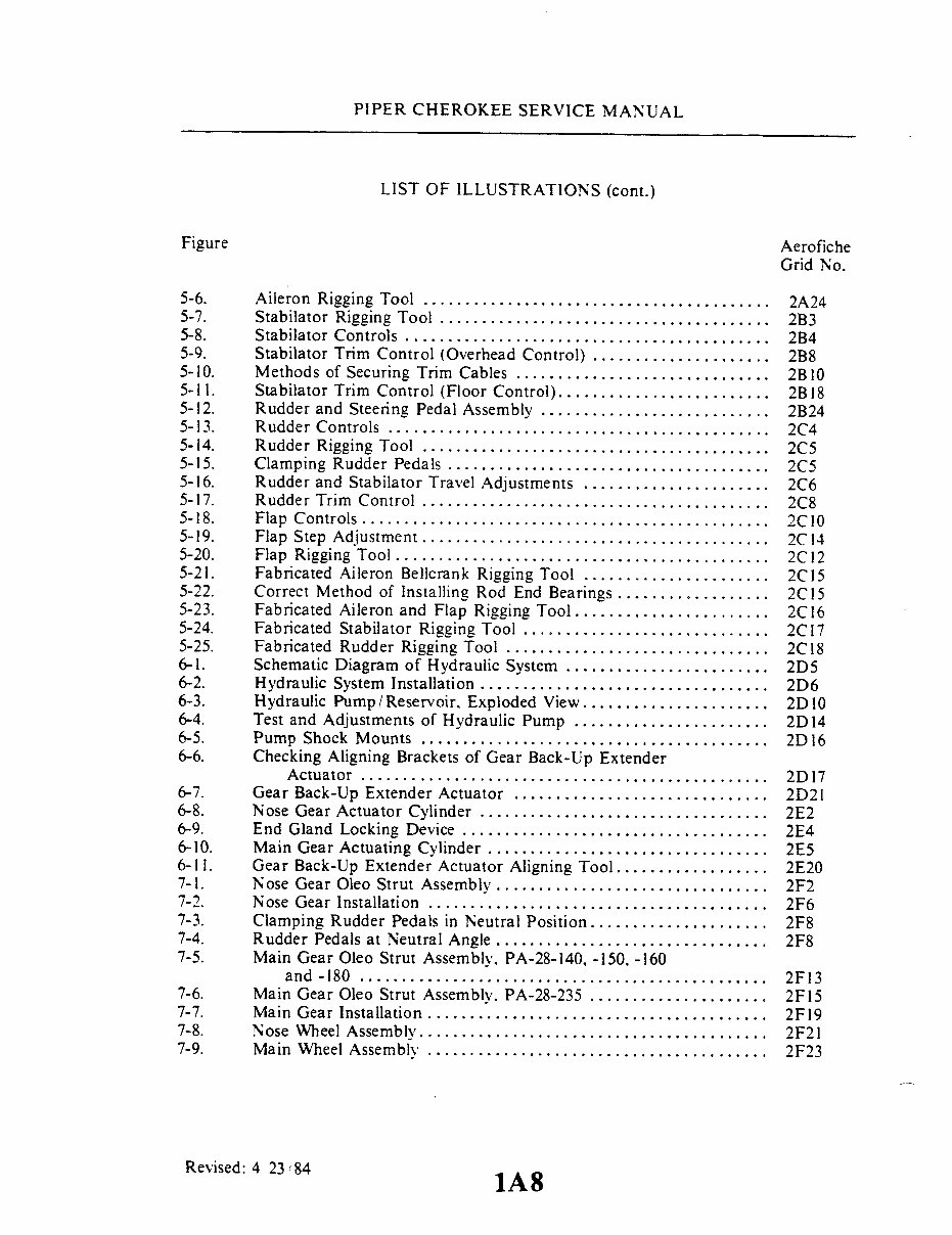
PIPER CHEROKEE SERVICE MANUAL LIST OF ILLUSTRATIONS (cont.) Figure Aerofiche Grid No. 5-6. Aileron Rigging Tool ......................................... 2A24 5-7. Stabilator Rigging Tool ....................................... 2B3 5-8. Stabilator Controls ....................................... .... 2B4 5-9. Stabilator Trim Control (Overhead Control) ... ............. 2B8 5-10. Methods of Securing Trim Cables .............................. 2B10 5-11. Stabilator Trim Control (Floor Control) ......................... 2B18 5-12. Rudder and Steering Pedal Assembly ........................... 2B24 5-13. Rudder Controls ............................................. 2C4 5-14. Rudder Rigging Tool .................................... 2C5 5-15. Clamping Rudder Pedals ...................................... 2C5 5-16. Rudder and Stabilator Travel Adjustments ... ................... 2C6 5-17. Rudder Trim Control ......................................... 2C8 5-18. Flap Controls ................... ............................. 2C10 5-19. Flap Step Adjustment ......................................... 2C14 5-20. Flap Rigging Tool ............................................ 2C12 5-21. Fabricated Aileron Bellcrank Rigging Tool ...................... 2C15 5-22. Correct Method of Installing Rod End Bearings .................. 2C15 5-23. Fabricated Aileron and Flap Rigging Tool ....................... 2C16 5-24. Fabricated Stabilator Rigging Tool ............................. 2C17 5-25. Fabricated Rudder Rigging Tool ............................... 2C18 6-1. Schematic Diagram of Hydraulic System ... .............. 2D5 6-2. Hydraulic System Installation .................................. 2D6 6-3. Hydraulic Pump/Reservoir. Exploded View ...................... 2D10 6-4. Test and Adjustments of Hydraulic Pump ............. ............... 2D14 6-5. Pump Shock Mounts ......................................... 2D16 6-6. Checking Aligning Brackets of Gear Back-Up Extender Actuator ................................................ 2D 17 6-7. Gear Back-Up Extender Actuator .............................. 2D21 6-8. Nose Gear Actuator Cylinder .................................. 2E2 6-9. End Gland Locking Device .................................... 2E4 6-10. Main Gear Actuating Cylinder ................................. 2E5 6-11. Gear Back-Up Extender Actuator Aligning Tool .................. 2E20 7-1. Nose Gear Oleo Strut Assembly ................................ 2F2 7-2. Nose Gear Installation ........................................ 2F6 7-3. Clamping Rudder Pedals in Neutral Position ..................... 2F8 7-4. Rudder Pedals at Neutral Angle .. ........................ ... 2F8 7-5. Main Gear Oleo Strut Assembly. PA-28-140, -150, -160 and -180 ................................................ 2F13 7-6. Main Gear Oleo Strut Assembly, PA-28-235 ..................... 2F15 7-7. Main Gear Installation ... ........................ .......... 2F19 7-8. Nose Wheel Assembly ......................................... 2F21 7-9. Main Wheel Assembly ........................................ 2F23 Revised: 4 23/84 1A8 1A8
PIPER CHEROKEE SERVICE MANUAL LIST OF ILLUSTRATIONS (cont.) Figure Aerofiche Grid No. 7-10. Wheel Brake Assembly ........................................ 2G1 7-11. Removal of Anchor Bolt ...................................... 2G2 7-12. Installation of Anchor Bolt .................................... 2G3 7-13. Brake Disc Minimum Thickness ................................ 2G5 7-14. Brake System Installation ..................................... 2G5 7-15. Brake Master Cylinder (Hand Brake). PA-28-150. -160. Serial Nos. 28-1 to 28-250 incl ............................. 2G8 7-16. Brake Master Cylinder (Hand Parking Brake), PA-28-140. Serial Nos. 28-20002 to 28-21036 incl.: PA-28-150. -160. -180. Serial Nos. 28-251 to 28-2700 incl.: PA-28-235. Serial Nos. 28-10003 to 28-10697 incl ............ 2G8 7-17. Brake Master Cylinder (Hand Parking Brake). PA-28-140. Serial Nos. 28-21037 and up: PA-28-150. -160. -180. Serial Nos. 28-2701 and up: PA-28-235. Serial Nos. 28-10698 and up.......................................... 2G9 7-18. Parking Valve. PA-28-150. -160. Serial Nos. 28-1 to 28-250 incl ............................................... 2G11 7-19. Toe Brake Installation ........................................ 2G12 7-20. Brake Cylinder 10-20. 10-27. 17000 (Toe Brake) .................. 2G14 7-21. Brake Cylinder 10-30 (Toe Brake) .............................. 2G 15 7-22. Bleeding Brake (Gravity) ...................................... 2G 18 7-23. Bleeding Brake (Pressure) ......... ............................ 2G 18 7-24. Orifice Replacement Tool ..................................... 2G23 7-25. Retainer Ring Tool ........................................... 2G24 7A-I. Nose Gear Oleo Strut Assembly ............................... . 2H9 7A-2. Nose Gear Installation ........................................ 2H 12 7A-3. Nose Gear Adjustment (Without Gear Up Stop) .................. 2H 16 7A-4. Nose Gear Adjustment (With Gear Up Stop) ...... ............... 2H 17 7A-5. Clamping Rudder Pedals in Neutral Position ..................... 2H 19 7A-6. Rudder Pedals at Neutral Angle ................................ 2H19 7A-7. Nose Gear Door Retraction Mechanism ............. .............. 2H20 7A-8. Main Gear Oleo Strut Assembly ............................... . 211 7A-9. Main Gear Installation ....................................... 214 7A-10. Aligning Main Gear .......................................... 2110 7A-11. Adjustment of Nose Gear Down Limit Switch .................... 2115 7A-12. Adjustment of Main Gear Down Limit Switch ................... 2115 7A-13. Wiring Diagram of Landing Gear Electrical Circuit ............... 2117 7A- 14. Throttle Warning Switches .................................... 2119 7A-15. Nose Wheel Assembly.......................................... 2122 7A-16. Main Wheel Assembly ........................................ 2123 7A-17. Wheel Brake Assembly .................... ................... 2J1 7A-18. Brake Disc Minimum Thickness ................................ 2J3 Revised: 8 3 81 1A9 1A9
Piper Cherokee PA-24 Aircrafts Service & Repair Manual
Models covered:
PA-28-140
PA-28-150
PA-28-160
PA-28-180
PA-28-235
PA-28R-180
PA-28R-200
The Piper Cherokee PA-24 Aircrafts Service & Repair Manual is a comprehensive technical guide covering the essential systems and components of these aircraft models. It provides precise diagrams and step-by-step instructions for the engine, airframe, landing gear, and electrical systems.
Clear guidance for routine maintenance tasks like oil changes, fuel system checks, and spark plug replacements is included. For more complex tasks, such as engine overhauls, landing gear adjustments, and avionics troubleshooting, the manual offers detailed diagnostic procedures and repair instructions. Accurate torque specifications, wiring diagrams, and system flow charts ensure efficient problem identification and resolution.
Suitable for both certified technicians and knowledgeable owners, this manual provides all the essential data needed to keep your Piper Cherokee PA-24 in prime condition. Its thorough guidance will help ensure the aircraft remains airworthy and dependable for every flight.
Format: PDF Language: English Compatibility: Compatible with various electronic devices, including PC, Mac, Android, and Apple devices. Requirements: Adobe Reader (free)
Recently Viewed
5,521,897Happy Clients
2,594,462eManuals
1,120,453Trusted Sellers
15Years in Business
Price:
Actual Price:
Piper Cherokee PA-24 Aircrafts OEM Service & Repair Manual