

Piper Comanche PA-24 Service Manual & Parts Catalog PA-24-180, PA-24-250, PA-24-260, PA-24-400 -
What's Included?
Fast Download Speeds
Offline Viewing
Access Contents & Bookmarks
Full Search Facility
Print one or all pages of your manual

REVISIONS STATUS
The information compiled in this Parts Catalog will be kept current by revisions distributed periodically.
Current Revisions to this PA-24 series Parts Catalog issued January 26, 1973 are as follows:
752 464 (ORG730126) ....................................................................Dated January 1973
752 464 (PR770415) .............................................................................Dated April 1977
752 464 (PR800513) .............................................................................Dated May 1980
752 464 (PR820909)...................................................................Dated September 1982
752 464 (IR980831) ..........................................................................Dated August 1998
752 464 (PR071210)....................................................................Dated December 2007
752 464 (PR090310) ..........................................................................Dated March 2009
PIPER PARTS CATALOG
REVISED: MARCH 10, 2009 PA-24-180
PA-24-250
PA-24-260
PA-24-400
1A2
PIPER PARTS CATALOG
INTRODUCTION
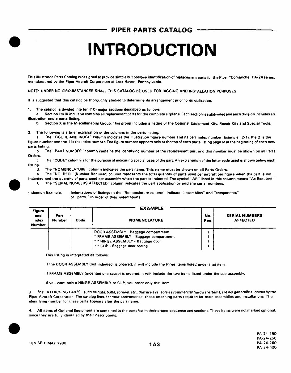
This illustrated Parts Catalog is designed to provide simple but positive identification of replacement parts for the Piper "Comanche" PA-24 series.
manufactured by the Piper Aircraft Corporation of Lock Haven, Pennsylvania
NOTE- UNDER NO CIRCUMSTANCESSHALL THIS CATALOG BE USED FOR RIGGING AND INSTALLATION PURPOSES
It is suggested that this catalog be thoroughly studied to determine its arrangement prior to its utilization.
1. The catalog is divided into ten (10) major sections described as follows:
a. Section I to IX inclusive contains all replacement parts for the complete airplane Each section is subdivided and each division includes an
illustration and a parts listing
b. Section X is the Miscellaneous Group. This group includes a listing of the Optional Equipment Kits. Repair Kits and Special Tools
2. The following is a brief explanation of the columns in the parts listing:
a. The "FIGURE AND INDEX" column indicates the illustration figure number and its part index number. Example. (2-1). the 2 is the
figure number and the 1 is the index number Thefigure number appears only at the top of each parts listing page or at the beginning of each new
parts listing.
b. The "PART NUMBER" column contains the identifying number of the replacement part and this number must be shown on all Parts
Orders.
c. The "CODE" column is for the purpose of indicating special uses of the part. An explanation of the letter code used is shown below each
listing
d. The "NOMENCLATURE" column indicates the pan name This name must be shown on all Parts Orders.
e The "NO. REQ." (Number Required) column represents the total quantity of parts used per aircraft per figure when the part is not
indented and the quantity of parts used per assembly when the part is indented The symbol "AR" listed in this column means "As Required"
f. The "SERIAL NUMBERS AFFECTED" column indicates the part application by airplane serial numbers.
Indention Example Indentations of listings in the "Nomenclature column" indicate "assemblies" and "components"
or "parts," in order of their indentations
Figure EXAMPLE
Figure
and Part No. SERIAL NUMBERS
Index Number Code NOMENCLATURE Req. AFFECTED
Number
DOOR ASSEMBLY - Baggage compartment 1
FRAME ASSEMBLY - Baggage compartment 1
HINGE ASSEMBLY - Baggage door 1
CLIP - Baggage door spring
This listing is interpreted as follows.
If the DOOR ASSEMBLY (not indentedl is ordered. it will include the three items listed under that item.
If FRAME ASSEMBLY (indented one space) is ordered, it will include the two items listed under the sub-assembly
If you want only a HINGE ASSEMBLY or CLIP, you order only that item
3 The "ATTACHING PARTS" such as nuts. bolts, screws. etc.. that are available as commercial hardware items, are not generally supplied by the
Piper Aircraft Corporation The catalog lists, for your convenience, those attaching parts required for main assemblies and installations The
identifying number for these parts appears after the part name
4 All items of Optional Equipment are contained in the parts list in their proper sequence and sections. These items were not marked optional,
since they are fully identified by their descriptions.
PA-24-180
PA-24-250
REVISED MAY 1980 1A3 PA-24-260
PA-24-400

GRID NUMBERING
Piper has ceased production of all Aerofiche (i.e., microfiche) products. The Aerofiche grid numbers will be removed in the next complete
revision. In the interim, as partial revisions occur, the Aerofiche grid numbering system may be modified, as explained below, to simplify
production.
Deviations from the legacy Aerofiche grid numbering system will occur when it becomes necessary to add pages to the manual and will
typically take two forms:
A. Inserting pages between two existing grids in the same row.
When inserting two pages between the existing grids 1A8 and 1A9, the two new pages will be numbered 1A8A and 1A8B.
B. Inserting pages at the end of an Aerofiche grid row.
The legacy Aerofiche grid numbering system limited page numbers in a row to a maximum of 24 (i.e., row 1A would be numbered 1A1-
1A24). That limit no longer applies. Accordingly, if two pages need to be added between any existing grid row end and grid row start
(ie., 1A24 and 1B1), the new pages will simply be numbered 1A25 and 1A26.
HOW TO IDENTIFY A PART
IF YOU KNOW WHAT IT LOOKS LIKE
AND KNOW WHERE IT IS LOCATED
1. Refer to Figure 1 to determine the Section number in which the part is used.
2. Refer to the Table of Contents and locate the section. Note the figure numbers that illustrate the various subgroups of this main section.
a. Select the figure title you think might contain the part you wish to identify and proceed to the grid (page) specified.
3. Find the part on the illustration and note the index number.
NOTE: If you don’t find the part on this illustration, try another figure in this group.
4. Refer to the “Figure and Index Number” in the Parts Listing for complete description of the part.
HOW TO ORDER PARTS
In ordering parts for your Piper airplane, observe the following instructions which will aid in your getting the right parts required without
delay:
a. Place your order with the distributor or dealer for your territory, since parts are available only through our distributor organization.
b. Always specify the model and serial number of your airplane.
c. Always specify Part Number, Name, Type and Quantity required.
d. Specify the method of shipment - freight, express, parcel post, air express, air freight, or air parcel post. Where the nature of the
shipment requires it or when no instructions are given, we reserve the right to ship the most suitable way.
GENERAL INFORMATION
a. Shortages
All orders are checked and rechecked before leaving our Shipping Department. A packing slip is enclosed with the shipment and claims
for errors or shortages must be made within three days after receipt of orders.
b. Returned Goods
No material should be returned to us without first securing our written permission. Material sent in without notice will be held at the
owner’s risk for thirty (30) days and will then be disposed of as we see fit.
Transportation charges must be PREPAID on returned goods or the shipment will be refused.
c. Transportation Liabilities
The Piper Aircraft Corporation cannot be held liable for damages to parts in transit from the factory. If a shipment is received in a dam-
aged condition, have the delivery man or Transportation Company make a notation of the damage and file your claim with the Carrier. In case
of concealed damage, do not attempt to remove the part from the shipping container, or endeavor to repair the damage, but call the Carrier
and have his Claim Agent inspect the damage before filing your claim with the Carrier.
PIPER PARTS CATALOG
REVISED: MARCH 10, 2009
PA-24-180
PA-24-250
PA-24-260
PA-24-400
1A4
PIPER PARTS CATALOG
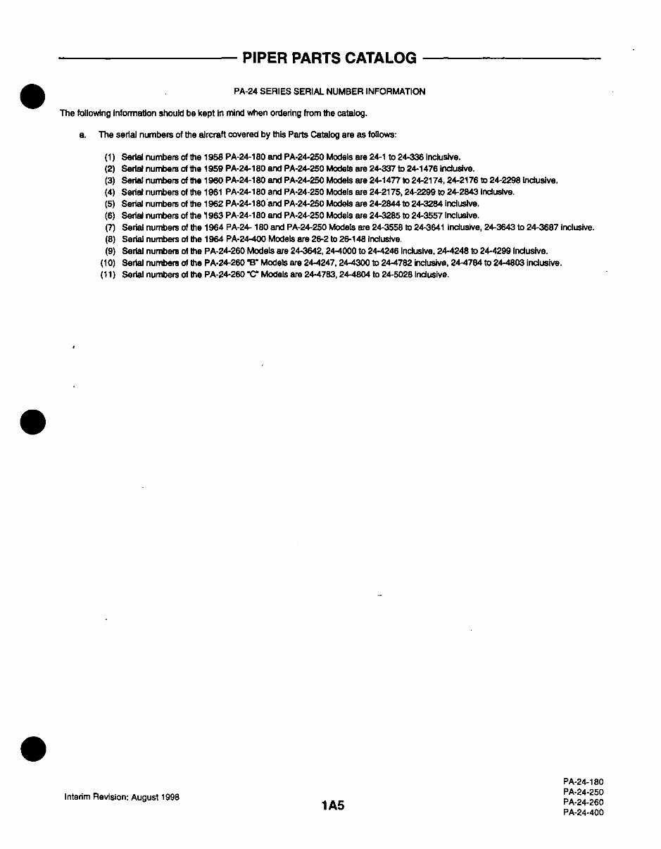
PA-24 SERIES SERIAL NUMBER INFORMATION
The following Information should bekept in mind when ordering fromthe catalog.
a. The serial numbers of the aircraft covered by this Parts Catalog are as follows:
(1) Serialnumbers of the 1958PA-24-180 and PA-24-250 Models are 24-1 to 24-336nclusive.
(2) Serialnumbers of the 1959PA-24-180 and PA-24-250 Models are 24-337 to 24-1476 inclusive.
(3) Serialnumbers of the 1960PA-24-180 and PA-24-250 Models are 24-1477 to 24-2174, 24-2176 to 24-2298 inclusive.
(4) Serialnumbers of the 1961PA-24-180 and PA-24-250 Models are 24-2175,24-2299 to 24-2843 Indusive.
(5) Serialnumbers of the 1962PA-24-180 and PA-24-250 Models are 24-2844 to 24-3284 inclusive.
(6) Serialnumbers of the 1963PA-24-180 and PA-24-250 Models are 24-3285 to 24-3557 Inclusive.
(7) Serial numbers of the 1964 PA-24- 180andPA-24-250 Models are24-3558 to 24-3641 inclusive, 24-3643 to 24-3687 Inclusive.
(8) Serial numbers of the 1964 PA-24-400 Models are 26-2 to 26-148 inclusive.
(9) Serial numbers of the PA-24-260 Models are24-3642, 244000to 24-4246 Inclusive, 24-4248 to 24-4299 Inclusive.
(10) Serial numbers of the PA-24-260 B Models are24-4247, 244300 to 24-4782 inclusive, 24-4784 to 24-4803 inclusive.
(11) Serial numbers of the PA-24-260 'C Models are24-4783, 24-4804 to 24-5028 Inclusive.
Interim Revision: August1998
PA-24-180
PA-24-250
PA-24-260
PA-24-400
1A5

STANDARD PAINT CHART
MFG. PIPER PART NUMBER
NO. QUART GALLON
EXTERIOR
ENAMEL
Daytona White J-9545 751 700 751 701
Santa Fe Red H-9150 751 712 751 713
Bahama Blue H-9170 751 714 751 715
Hershey Brown H-9160 751 716 751 717
Montego Green F-5830 751 718 751 719
Yukon Yellow W-0232 751 720 751 721
Pontiac Red W-3665 754 716 754 717
Portland Green W-3558 754 724 754 725
Phoenix Tan W-3557 754 718 754 719
Orlando Green W-3680 754 720 754 721
Lakeland Blue W-3554 754 722 754 723
Dakota Black H-6117 751 710 751 711
El Paso Brown W-8433 754 737 754 738
Tampa Green W-8427 754 739 754 740
Newport Blue W-8430 754 741 754 742
ACRYLIC LACQUER
Daytona White 890-910 4175 650 1175 650
Phoenix Tan 890-908 4175 625 1175 625
El Paso Brown 893-62885 4175 403 1175 403
Juneau White L8973 4175 655 1175 655
Monterey Maroon (base coat) 8908 4175 758 1175 758
Monterey Maroon (top coat) 8904 4175 757 1175 757
Madrid Red (base coat) 8276 4175 131 1175 131
Madrid Red (top coat) 8910 4175 589 1175 589
Denver Brown (base coat) 8989 4175 297 1175 297
Denver Brown (top coat) 8977 4175 298 1175 298
Tampa Green (base coat) 8998 4175 208 1175 208
Tampa Green (top coat) 8997 4175 207 1175 207
Newport Blue (base coat) 8988 4175 756 1175 756
Newport Blue (top coat) 8991 4175 755 1175 755
Beaumont Blue 8993 4175 754 1175 754
Bahama Blue 8911 4175 442 1175 442
Lakeland Blue 8979 4175 753 1175 753
Orlando Green 8981 4175 206 1175 206
Mocha Tan 8985 4175 750 1175 750
Pontiac Red 8954 4175 590 1175 590
Dakota Black 8906 4175 375 1175 375
Polar Gray 8986 4175 204 1175 204
Reno Gold (base coat) 8976 4175 343 1175 343
Reno Gold (top coat) 8974 4175 342 1175 342
Nassau Turquoise 8978 4175 751 1175 751
Bemini Turquoise 8992 4175 752 1175 752
Ocala Orange (base coat) 8909 4175 503 1175 503
Ocala Orange (top coat) 8907 4175 502 1175 502
Dallas Yellow 8975 4175 702 1175 702
Lincoln Gray 8987 4175 205 1175 205
Las Vegas Gold (base coat) 8931 4175 327 1175 327
Las Vegas Gold (top coat) 8929 4175 328 1175 328
Avocado 8955 4175 209 1175 209
Thinner (fast drying) Titanine 8930 4179 138 1179 138
Thinner (slow drying) Titanine 8970 4179 134 1179 134
Thinner (Dupont)
COLOR PAINT (For Thermoplastic Interior Trim Panels Only) AVAILABLE IN 16-OUNCE AEROSAL CANS
Avocado Green 766-007
White 766-008
Tan 766-009
Red 766-010
Dark Blue 766-011
Light Blue 766-012
Sandstone 766-013
Gloss Black 766-014
Dark Brown 766-015
Brown 766-016
Blue-Green 766-017
Optical Flat Black 766-018
PIPER PARTS CATALOG
REVISED: DECEMBER 10, 2007
PA-24-180
PA-24-250
PA-24-260
PA-24-400
1A6

1A7
INTENTIONALLY LEFT BLANK
PIPER PARTS CATALOG
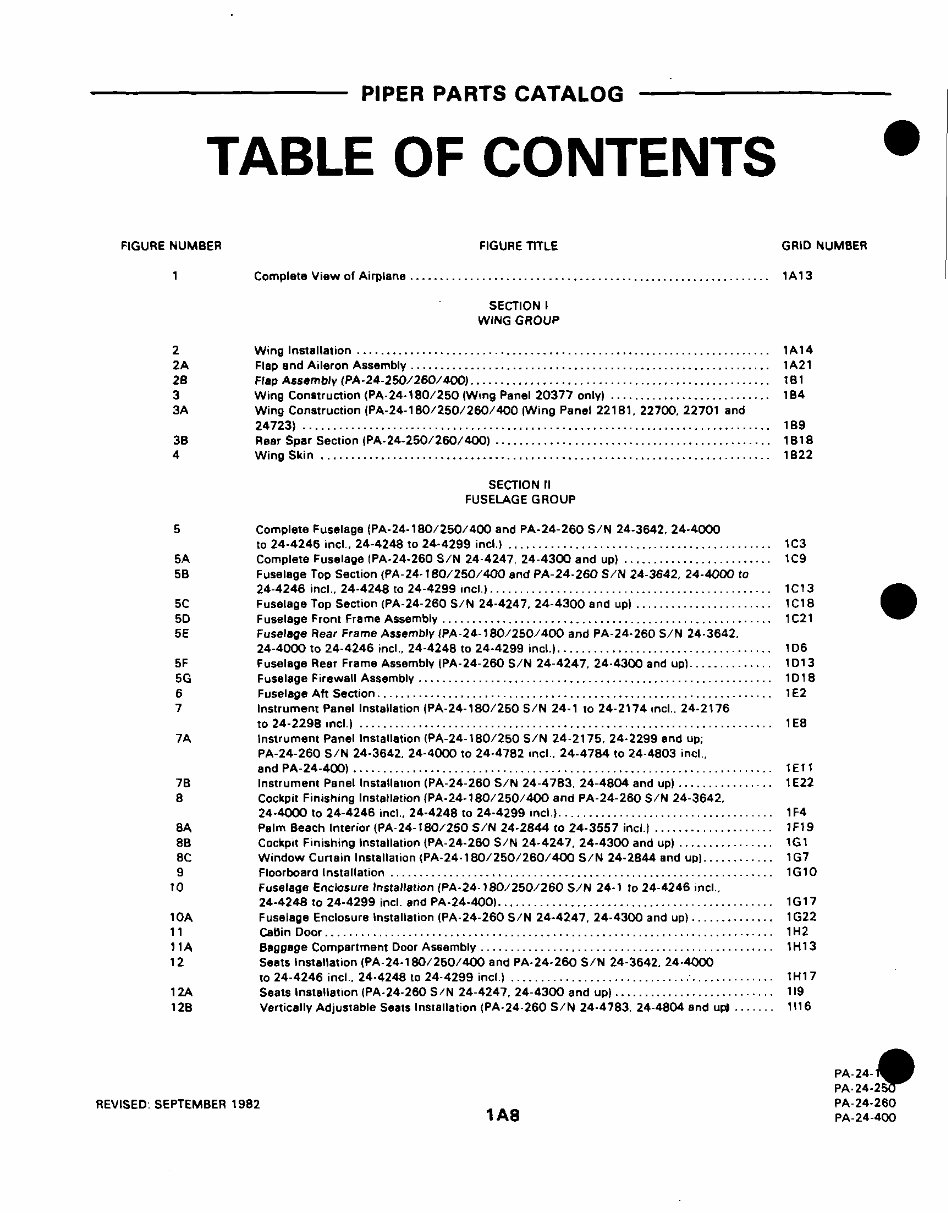
TABLEOF CONTENTS
FIGURE NUMBER FIGURE TITLE GRID NUMBER
1 Complete View of Airplane ............................................................ 1A13
SECTION I
WING GROUP
2 Wing Installation ..................................................................... 1A14
2A Flap and Aileron Assembly ........................................................... 1A21
28 Flap Assembly (PA-24-250/260/400) ............................ ...................... 181
3 Wing Construction (PA-24-180/250 (Wing Panel 20377 only) ........................... 184
3A Wing Construction (PA-24-180/250/260/400 (Wing Panel 22181. 22700. 22701 and
24723) ............................................................................. 189
3B Rear Spar Section (PA-24-250/260/400) .............................................. 1B18
4 Wing Skin ........................................................................... 1822
SECTION II
FUSELAGEGROUP
5 Complete Fuselage (PA-24-180/250/400 and PA-24-260 S/N 24-3642, 24-4000
to 24-4246 incl 24-4248 to 24-4299 incl.) ............................................ 1C3
5A Complete Fuselage (PA-24-260 S/N 24-4247, 24-4300 and up) ......................... 1C9
5B Fuselage Top Section (PA-24-180/250/400 and PA-24-260 S/N 24-3642, 24-4000 to
24-4246 incl.. 24-4248 to 24-4299 incl ) ............................................... 1C13
5C Fuselage Top Section (PA-24-260 S/N 24-4247, 24-4300 and up) ....................... 1C18
5D Fuselage Front Frame Assembly ....................................................... 1 C21
5E Fuselage Rear Frame Assembly {PA-24-180/250/400 and PA-24-260 S/N 24-3642.
24-4000 to 24-4246 incl.. 24-4248 to 24-4299 incl.) ................................... 1D6
5F Fuselage Rear Frame Assembly (PA-24-260 S/N 24-4247, 24-4300 and up).............. 1013
5G Fuselage Firewall Assembly ........................................................... 1D18
6 Fuselage Aft Section ................................................................. E2
7 Instrument Panel Installation (PA-24-180/250 S/N 24-1 to 24-2174 incl.. 24-2176
to 24-2298 inc l ) ..................................................................... 1 E8
7A Instrument Panel Installation (PA-24-180/250 S/N 24-2175. 24-2299 and up.
PA-24-260 S/N 24-3642. 24-4000 to 24-4782 incl. 24-4784 to 24-4803 incl,
and PA-24-400) ...................................................................... 1E
7B Instrument Panel Installation (PA-24-260 S/N 24-4783. 24-4804 and up) ............. .. 1E22
8 Cockpit Finishing Installation (PA-24-180/250/400 and PA-24-260 S/N 24-3642.
24-4000 to 24-4246 incl., 24-4248 to 24-4299 inc ) ................................... 1F4
8A Palm Beach Interior (PA-24-180/250 S/N 24-2844 to 24-3557 incl.) ...... ............. IF19
8B Cockpit Finishing Installation (PA-24-260 S/N 24-4247. 24-4300 and up) ................ 1G1
8C Window Curtain Installation (PA-24-180/250/260/400 S/N 24-2844 and up)............ 1G7
9 Floorboard Installation ................................................................ 1G10
10 Fuselage Enclosure Installation (PA-24-180/250/260 S/N 24-1 to 24-4246 incl.
24-4248 to 24-4299 inc. and PA-24-400) ................... ........................... G17
10A Fuselage Enclosure Installation (PA-24-260 S/N 24-4247, 24-4300 and up).............. 1G22
11 CaBin Door .......................................................................... 1H2
11A Baggage Compartment Door Assembly ................................................. 1H13
12 Seats Installation (PA-24-180/250/400 and PA-24-260 S/N 24-3642. 24-4000
to 24-4246 mcl. 24-4248 to 24-4299 incl ............................................ IH17
12A Seats Installation (PA-24-260 S/N 24-4247, 24-4300 and up) ........................... 119
12B Vertically Adjustable Seats Installation (PA-24-260 S/N 24-4783. 24-4804 and up) ....... 1116
PA-24-
PA-24-250
REVISED SEPTEMBER 1982 PA-24-260
1A8 PA-24-400
PIPER PARTS CATALOG
TABLE OF CONTENTS
FIGURE NUMBER FIGURE TITLE GRID NUMBER
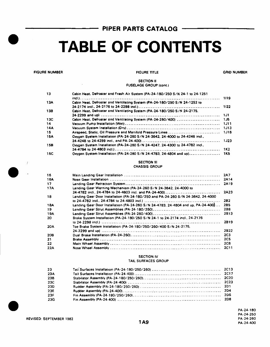
SECTION II
FUSELAGEGROUP (cont.)
13 Cabin Heat, Defroster and Fresh Air System (PA-24-180/250 S/N 24-1 to 24-1251
incl.)...... ............................................. 1119
13A Cabin Heat, Defroster and Ventilating System (PA-24-180/250 S/N 24-1252 to
24-2174 incl.. 24-2176 to 24-2298 incl.) ............................................... 1122
13B Cabin Heat, Defroster and Ventilating System (PA-24-180/250 S/N 24-2175.
24-2299 and up) ............................................................ ......... 1J1
13C Cabin Heat, Defroster and Ventilating System (PA-24-260/400) ... ...................... 1J5
14 Vacuum Pump Installation (Wet) ................. ................. .............. 1J11
14A Vacuum System Installation (Dry) ................... .................. ........... 1J13
15 Airspeed, Static. Oil Pressure and Manifold Pressure Lines .............................. 1J18
15A Oxygen System Installation (PA-24-260 S/N 24-3642. 24-4000 to 24-4246 incl..
24-4248 to 24-4299 incl., and PA-24-400) ............................................. 1J23
15B Oxygen System Installation (PA-24-260 S/N 24-4247, 24-4300 to 24-4782 incl.,
24-4784 to 24-4803 incl.) ............................................................. 1K2
15C Oxygen System Installation (PA-24-260 S/N 24-4783, 24-4804 and up) ................. 1K5
SECTION III
CHASSIS GROUP
1 6 Main Landing Gear Installation ........................................................ 2A7
16A Nose Gear Installation ................................................................ 2A14
17 Landing Gear Retraction System ....................................................... 2A19
17A Landing Gear Warning Mechanism (PA-24-260 S/N 24-3642. 24-4000 to
24-4782 inc . 24-4784 to 24-4803 incl and PA-24-400) ........ ............ ............ 2A23
18 Landing Gear Door Installation (PA-24-180/250 and PA-24-260 S/N 24-3642. 24-4000
to 24-4782 incl.. 24-4784 to 24-4803 c ) ........................................... 2B2
18A Landing Gear Door Installation (PA-24-260 S/N 24-4783. 24-4804 and up, PA-24-400)... 285
19 Landing Gear Strut Assemblies (PA-24-180/250) ................ . ....... .......... . 2B8
19A Landing Gear Strut Assemblies (PA-24-260/400) ................ -2... .... ............. 2 13
20 Brake System Installation (PA-24-180/250 S/N 24-1 to 24-2174 incl.. 24-2176
to 24-2298 incl.) ..................................................................... 2 19
20A Toe Brake System Installation {PA-24-180/250/260/400 S/N 24-2175.
24-2299 and up) ......... .......................................... 2B22
208 Dual Brake Installation (PA-24-260) .................................................... 2C3
21 Brake Assembly ...................................................................... 2C5
22 Main Wheel Assembly ................................................................ 2C8
22A Nose Wheel Assembly ................................................................ 2C11
SECTION IV
TAIL SURFACES GROUP
23 Tall'Surfaces Installation (PA-24-180/250/260) ........................................ 2C13
23A Tail Surfaces Installation (PA-24-400) ................. .. ............................. 2C17
238 Stabilator Assembly (PA-24-180/250/260) ............................................ 2C20
23C Stabilator Assembly (PA-24-400) ............................... ....................... 2C23
23D Rudder Assembly (PA-24-180/250/260) ............................................... 2D1
23E Rudder Assembly (PA-24-400) ......................................................... 2D4
23F Fin Assembly (PA-24-180/250/260) ........................... ....... .............. 2D6
23G Fin Assembly (PA-24-400) ...................................................... ... 2D8
PA-24-180
PA-24-250
REVISED SEPTEMBER 1982 PA-24-260
A9 PA-24-400
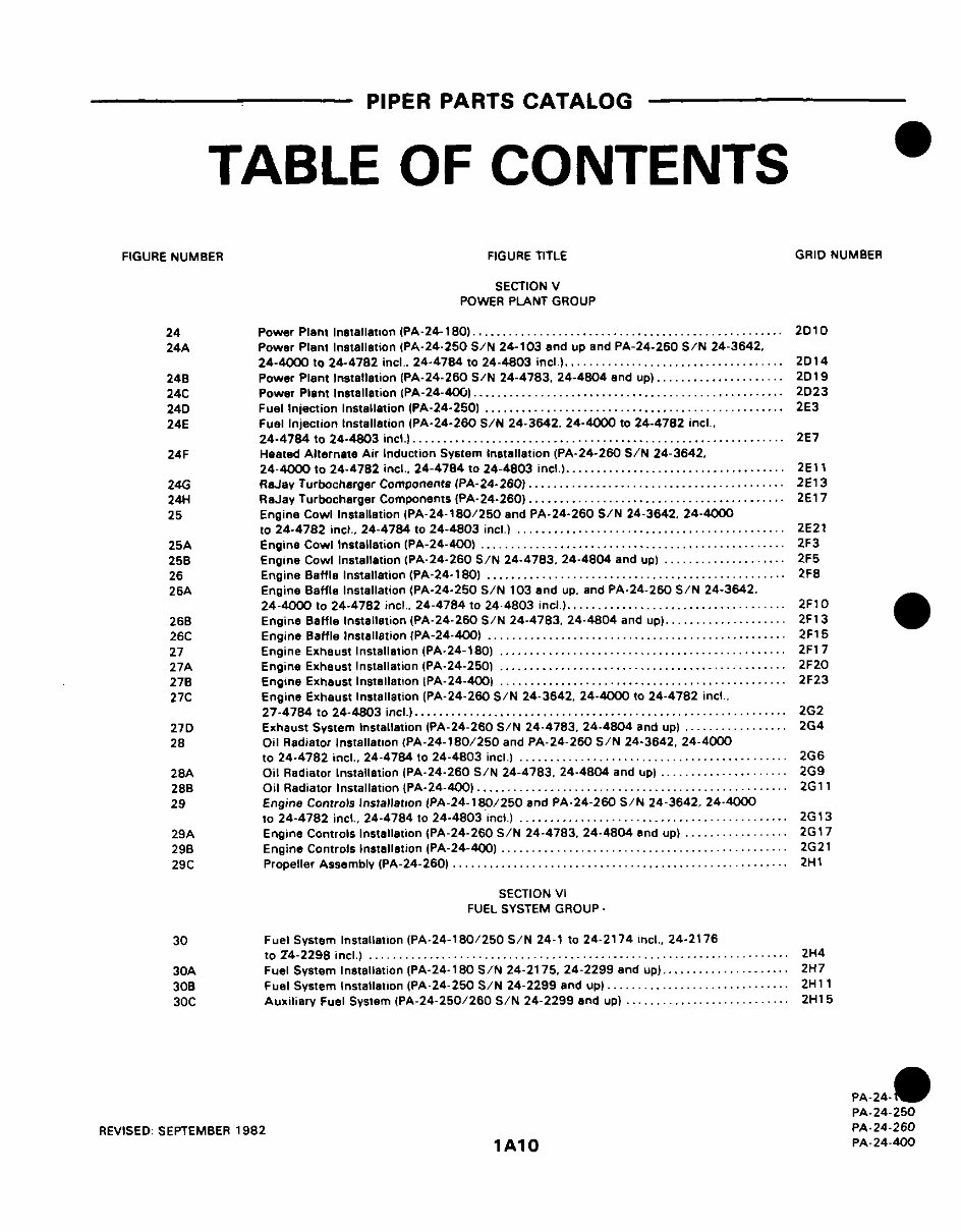
PIPER PARTS CATALOG
TABLEOF CONTENTS
FIGURE NUMBER FIGURE TITLE GRID NUMBER
SECTION V
POWER PLANT GROUP
24 Power Plant Installation (PA-24-180) . .................................. .......... 2D10
24A Power Plant Installation (PA-24-250 S/N 24-103 and up and PA-24-260 S/N 24-3642,
24-4000 to 24-4782 incl. 24-4784 to 24-4803 incl ) .................................... 2D14
248 Power Plant Installation (PA-24-260 S/N 24-4783, 24-4804 and up) ..................... 2D19
24C Power Plant Installation (PA-24-400) ................................................... 2D23
24D Fuel Inlection Installation (PA-24-250) ................................................. 2E3
24E Fuel Injection Installation (PA-24-260 S/N 24-3642. 24-4000 to 24-4782 incl,
24-4784 to 24-4803 incl.) ............................................................. 2E7
24F Heated Alternate Air Induction System Installation (PA-24-260 S/N 24-3642,
24-4000 to 24-4782 incl., 24-4784 to 24-4803 incl) .................................... 2E11
24G RaJay Turbocharger Components (PA-24-260) ......................................... 2E13
24H RaJay Turbocharger Components {PA-24-260) .......................................... 2E17
25 Engine Cowl Installation (PA-24-180/250 and PA-24-260 S/N 24-3642. 24-4000
to 24-4782 incl., 24-4784 to 24-4803 incl ) .......... ......................... ... 2E21
25A Engine Cowl Installation (PA-24-400) .................................................. 2F3
25B Engine Cowl Installation (PA-24-260 S/N 24-4783. 24-4804 and up) .................... 2F5
26 Engine Baffle Installation (PA-24-180) ................................................ 2F8
26A Engine Baffle Installation (PA-24-250 S/N 103 and up. and PA-24-260 S/N 24-3642.
24-4000 to 24-4782 incl. 24-4784 to 24-4803 mcl ) .................................... 2F10
268 Engine Baffle Installation (PA-24-260 S/N 24-4783. 24-4804 and up) .................... 2F1 3
26C Engine Baffle Installation (PA-24-400) .................... ............................. 2F15
27 Engine Exhaust Installation (PA-24-180) .............................. ................. 2F17
27A Engine Exhaust Installation (PA-24-2501 ...................................... ......... 2F20
278 Engine Exhaust Installation (PA-24-400) ............................................... 2F23
27C Engine Exhaust Installation (PA-24-260 S/N 24-3642. 24-4000 to 24-4782 incl .
27-4784 to 24-4803 incl.) ............................................................. 2G2
27D Exhaust System Installation (PA-24-260 S/N 24-4783. 24-4804 and up) ................. 2G4
28 Oil Radiator Installation (PA-24-180/250 and PA-24-260 S/N 24-3642, 24-4000
to 24-4782 mncl., 24-4784 to 24-4803 incl ) ............................................ 2G6
28A Oil Radiator Installation (PA-24-260 S/N 24-4783. 24-4804 and up) ..................... 2G9
28B Oil Radiator Installation {PA-24-400) ............................... .................... 2G11
29 Engine Controls Installation IPA-24-180/250 and PA-24-260 S/N 24-3642. 24-4000
to 24-4782 incl., 24-4784 to 24-4803 mcl ) ............................................ 2G13
29A Engine Controls Installation {PA-24-260 S/N 24-4783. 24-4804 and up) ........... ...... 2G17
29B Engine Controls Installation (PA-24-400) ............................................... 2G21
29C Propeller Assembly (PA-24-260) .............................................. ........ 2H1
SECTION VI
FUEL SYSTEM GROUP -
30 Fuel System Installation (PA-24-180/250 S/N 24-1 to 24-2174 incl., 24-2176
to 24-2298 incl.) ........................ ................... ........................... 2H4
30A Fuel System Installation (PA-24-180 S/N 24-2175, 24-2299 and up) ..................... 2H7
30B Fuel System Installation (PA-24-250 S/N 24-2299 and up) ...... ........................ 2H 11
30C Auxiliary Fuel System (PA-24-250/260 S/N 24-2299 and up) ........ ................... 2H15
PA-24- 0
PA-24-250
REVISED SEPTEMBER 1982 PA-24-260
1A10 PA-24-400
You're Reading a Preview
What's Included?
Fast Download Speeds
Offline Viewing
Access Contents & Bookmarks
Full Search Facility
Print one or all pages of your manual
$39.99
Viewed 84 Times Today


Secure transaction
What's Included?
Fast Download Speeds
Offline Viewing
Access Contents & Bookmarks
Full Search Facility
Print one or all pages of your manual
$39.99
- The Complete Factory Piper Comanche PA-24, PA-24-180, PA-24-250, PA-24-260, PA-24-400 Service Repair Manual & the Illustrated Parts Catalog are the newest revisions dated 2009.
- These technical manuals provide instructions to maintain, service, and replace parts on the Piper Comanche PA-24 series airplanes using detailed diagrams and manufacturers specifications.
- Effective for all PA-24 Comanche series airplanes, including various model years and serial numbers.
- Navigation is simple with chapter bookmarks and the ability to search by keyword.
- Print out entire manuals or just the relevant sections for your work.
- Instant access with no waiting, available in English language and compatible with all versions of Windows & Mac.
- Completely bookmarked chapters for easy navigation and comprehensive illustrations, exploded diagrams, drawings, and photos to guide you through the service repair procedures.
- Both manuals are indexed, bookmarked, and searchable.
- Service manual sections include Introduction, Airworthiness Limitations, Handling & Servicing, Inspection, Structures, Surface Controls, Landing Gear & Brakes, Power Plant, Fuel System, Electrical System, Heating & Ventilation System, Instruments, Electronics, Accessories And Utilities.
- Parts manual sections include Introduction, Wing Group, Fuselage Group, Chassis Group, Tail Surfaces Group, Power Plant Group, Fuel System Group, Electrical System Group, Control System Group, Electronics Group, Miscellaneous Group.
- These manuals are perfect for tune-ups, maintenance, and repairs, providing mechanical details and step-by-step instructions.
- Additional Information: Documents may require the newest version of Acrobat Reader to display correctly. Should you have any problems reading your document, please initially try upgrading to the latest version of Adobe Acrobat Reader.
- For any inquiries about other manuals, feel free to email.


