

Mooney M20 B C D E IPC parts manual 1961 - 1964
What's Included?
Fast Download Speeds
Online & Offline Access
Access PDF Contents & Bookmarks
Full Search Facility
Print one or all pages of your manual
SPARE PARTS
MANUAL
# 1701B--1939B
# 1940C--2296C
# 2297C--2622C
# 2623C--2806C
# 101D--200D
# 201D--251D
# 101E--469E
Revised: October 15, 1963
Corrected: January 1966
1961, M-20B
1962, M-20C
1963, M-20C
1964, M-20C
1963, M-20D
1964, M-20D
1964, M-20E
MOONEY AIRCRAFT, INC.
Spare Parts Department
P .00 Box 72
Kerrville, Texas 78028

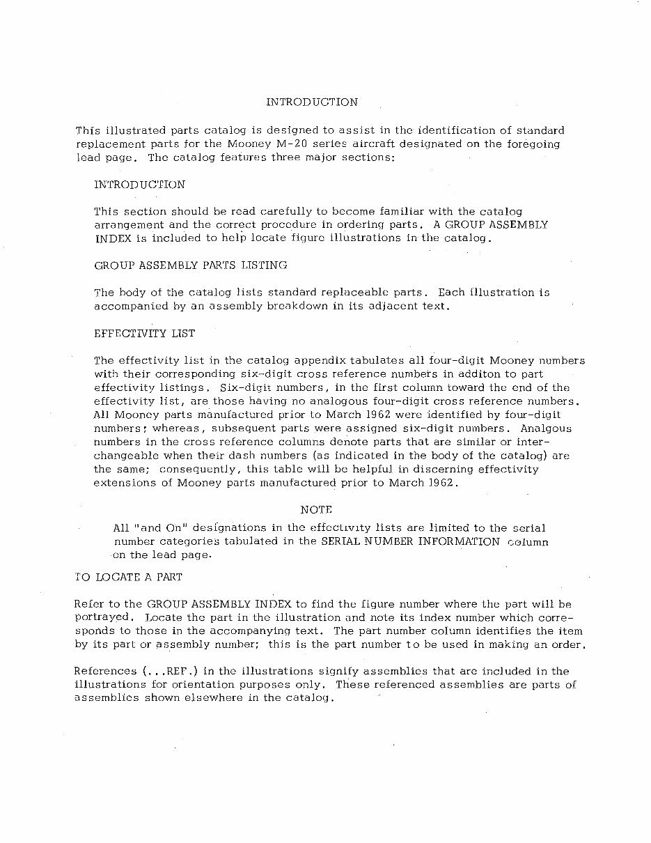
INTRODUCTION
This illustrated parts catalog is designed to assist in the identification of standard
replacement parts for the Mooney M-20 series aircraft designated on the foregoing
lead page. The catalog features three major sections:
INTRODUCTION
This section should be read carefully to become familiar with the catalog
arrangement and the correct procedure in ordering parts. A GROUP ASSEMBLY
INDEX is included to help locate figure illustrations in the catalog.
GROUP ASSEMBLY PARTS LISTING
The body of the catalog lists standard replaceable parts. Each illustration is
accompanied by an assembly breakdown in its adjacent text.
EFFECTIVITY LIST
The effectivity list in the catalog appendix tabulates all four--digit Mooney numbers
with their corresponding six-digit cross reference numbers in additon to part
effectivity listings. Six-digit numbers I in the first column toward the end of the
effectivity list I are those having no analogous four-digit cros s reference numbers.
All Mooney parts manufactured prior to March 1962 were identified by four-digit
numbers r whereas I subsequent parts were assigned six-digit numbers. Analgous
numbers in the cross reference columns denote parts that are similar or inter-
changeable when their dash numbers (as indicated in the body of the catalog) are
the same; consequently I this table will be helpful in discerning effectivity
extensions of Mooney parts manufactured prior to March 1962.
NOTE
All "and On" deslgnations in the effectIvIty lists are limited to the serial
number categories tabulated in the SERIAL NUMBER INFORMATION c01umn
on the lead page.
TO LOCATE A PART
Refer to the GROUP ASSEMBLY INDEX to find the figure number where the part will be
portrayed. Locate the part in the illustration and note its index number which corre-
sponds to those in the accompanying text. The part number column identifies the item
by its part or assembly number; this is the part number to be used in making an order.
References ( ... REF.) in the illustrations signify assemblies that are included in the
illustrations for orientation purposes only. These referenced assemblies are parts of
assemblies shown elsewhere in the catalog.
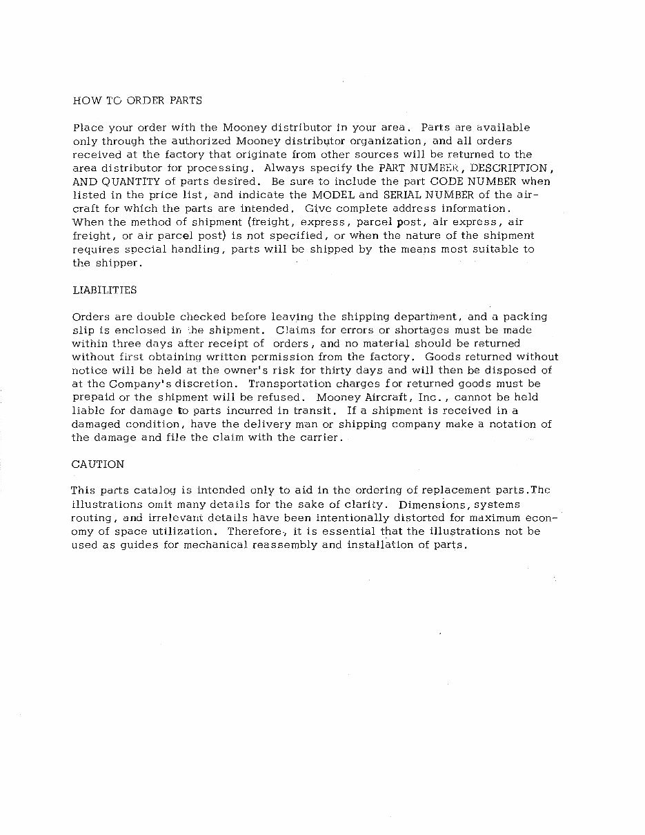
HOW TG ORDER PARTS
Place your order with the Mooney distributor in your area. Parts are available
only through the authorized Mooney distribl,ltor organization I and all orders
received at the factory that originate from other sources will be returned to the
area distributor for processing. Always specify the PART NUMBER, DESCRIPTION,
AND QUANTITY of parts desired. Be sure to include the part CODE NUMBER when
listed in the price list I and indicate the MODEL and SERIAL NUMBER of the air-
craft for which the parts are intended. Give complete address information.
When the method of shipment (freight I express I parcel post I air express I air
freight I or air parcel post) is not specified I or when the nature of the shipment
requires special handling I parts will be shipped by the means most suitable to
the shipper.
LIABILITIES
Orders are double checked before leaving the shipping departinent I and a packing
slip is enclosed in ::he shipment. Claims for errors or shorta<Jes must be made
within three days after receipt of orders I and no material should be returned
without first obtaining written permission from the factory. Goods returned without
notice will be held at the owner's risk for thirty days and will then be disposed of
at the Company's discretion. Transportation charges £ or returned goods must be
prepaid or the shipment will be refused. Mooney Aircraft I Inc. I cannot be held
liable for damage to parts incurred in transit. If a shipment is received in a
damaged condition I have the delivery man or shipping company make a notation of
the damage and file the claim with the carrier.
CAUTION
This parts catalog is intended only to aid in the ordering of replacement parts. Thc
illustrations omit many details for the sake of clarity. Dimensions I systems
routing I and irrelevallt details have been intentionally distorted for maximum econ-
omy of space utilization. Therefore·, it is essential that the illustrations not be
used as guides for mechanical reassembly and installation of parts.
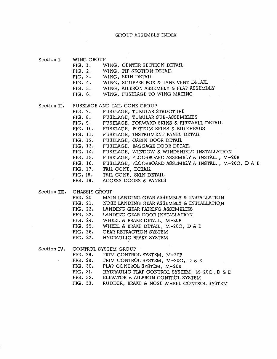
GROUP ASSEMBLY INDEX
Section L WING GROUP
1
FIG. 1. WING, CENTER SECTION DETAIL
FIG. 2. WING, TIP SECTION DETAIL
FIG. 3. WING, SKIN DETAIL
FIG. 4. WING, SCUPPER BOX & TANK VENT DETAIL
FIG. 5. WING, AILERON ASSEMBLY & FLAP ASSEMBLY
FIG. 6. WING, FUSELAGE TO WING MATING
Section II. FUSELAGE AND TAIL CONE GROUP 20
FIG. 7. FUSELAGE, TUBULAR STRUCTURE
FIG. 8. FUSELAGE, TUBULAR SUB-ASSEMBLIES
FIG. 9. FUSELAGE, FORWARD SKINS & FIREWALL DETAIL
FIG. 10. FUSELAGE, BOTTOM SKINS & BULKHEADS
FIG. 11. FUSELAGE, INSTRUMENT PANEL DETAIL
FIG. 12. FUSELAGE, CABIN DOOR DETAIL
FIG. 13. FUSELAGE, BAGGAGE DOOR DETAIL
FIG. 14. FUSELAGE, WINDOW & WINDSmELD INSTALLATION
FIG. 15. FUSELAGE, FLOORBOARD ASSEMBLY & INSTAL_ , M-20B
FIG. 16. FUSELAGE, FLOORBOARD ASSEMBLY & INSTAL. , M-20C, D & E
FIG. 17. TAIL CONE, DETAIL
FIG. 18. TAIL CONE, SKIN DETAIL
FIG. 19. ACCESS DOORS & PANELS
Section III. CHASSIS GROUP
FIG. 20
FIG. 21.
FIG. 22.
FIG. 23.
FIG. 24.
FIG. 25.
FIG. 26.
FIG. 27.
MAIN LANDING GEAR ASSEMBLY & INS'mLLATION
NOSE LANDING GEAR ASSEMBLY & INSTALLATION
LANDING GEAR FAIRING ASSEMBLIES
LANDING GEAR DOOR INSTALLATION
WHEEL & BRAKE DETAIL, M-20B
WHEEL & BRAKE DETAIL, M-20C, D & E
GEAR RETRACTION SYSTEM
HYDRAULIC BRAKE SYSTEM
Section IV. CONTROL SYSTEM GROUP
FIG. 28. TRIM CONTROL SYSTEM, M-20B
FIG. 29. TRIM CONTROL SYSTEM, M-20C, D & E
FIG. 30. FLAP CONTROL SYSTEM, M-20B
FIG. 31. HYDRAULIC FLAP CONTROL SYSTEM, M-20C, D &: E
FIG. 32. ELEVATOR & AILERON CONTROL SYSTEM
FIG. 33. RUDDER, BRAKE & NOSE WHEEL CONTROL SYSTEM
77
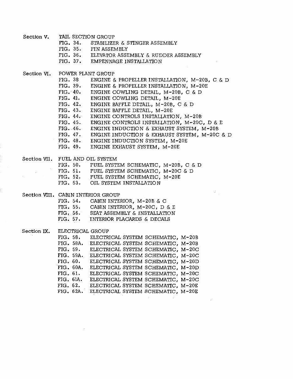
Section V. TAIL SECTION GROUP 94
FIG. 34. STABILIZER & STINGER ASSEMBLY
FIG. 35. FIN ASSEMBLY
FIG. 36. ELEVATOR ASSEMBLY & RUDDER ASSEMBLY
FIG. 37. EMPENNAGE INSTALLATION
Section VI. POWER PLANT GROUP 104
FIG. 38 ENGINE & PROPELLER INSTALLATION, M-20B, C & D
FIG. 39. ENGINE & PROPELLER INSTALLATION, M-20E
FIG. 40. ENGINE COWLING DETAIL, M-20B, C & D
FIG. 41. ENGINE COWLING DETAIL, M -20E
FIG. 42. ENGINE BAFFLE DETAIL, M-20B, C & D
FIG. 43. ENGINE BAFFLE DETAIL, M-20E
FIG. 44. ENGINE CONTROLS INSTALLATION, M-20B
FIG. 45. ENGINE CONTROLS INSTALLATION, M-20C, D & E
FIG. 46. ENGINE INDUCTION & EXHAUST SYSTEM, M-20B
FIG. 47. ENGINE INDUCTION & EXHAUST SYSTEM, M-20C & D
FIG. 48. ENGINE INDUCTION SYSTEM, M-20E
FIG. 49. ENGINE EXHAUST SYSTEM, M-20E
Section VII. FUEL AND OIL SYSTEM 132
FIG. 50. FUEL SYSTEM SCHEMATIC, M-20B, C & D
FIG. 51. FUEL SYSTEM SCHEMATIC I M -20C & D
FIG. 52. FUEL SYSTEM SCHEMATIC, M-20E
FIG. 53. OIL SYSTEM INSTALLATION
Section VIII. CABIN INTERIOR GROUP 142
FIG. 54. CABIN INTERIOR, M-20B & C
FIG. 55. CABIN INTERIOR, M -20C, D & E
FIG~ 56. SEAT ASSEMBLY & INSTALLATION
FIG. 57. INTERIOR PLACARDS & DECALS
Section IX. ELECTRICAL GROUP 156
FIG. 58. ELECTRICAL SYSTEM SCHEMATIC, M-20B
FIG. 58A. ELECTRICAL SYSTEM SCHEMATIC, M-20B
FIG. 59. ELECTRICAL SYSTEM SCHEMATIC, M-20C
FIG. 59A. ELECTRICAL SYSTEM SCHEMATIC, M-20C
FIG. 60. ELECTRICAL SYSTEM SCHEMATIC, M-20D
'FIG. 60A. ELECTRICAL SYSTEM SCHEMATIC, M -20D
FIG. 61. ELECTRICAL SYSTEM SCHEMATIC, M-20C
FIG. 6lA. ELECTRICAL SYSTEM SCHEMATIC, M-20C
FIG. 62. ELECTRICAL SYSTEM SCHEMATIC, M-20E
FIG. 62A. ELECTRICAL SYSTEM SCHEMATIC, M-20E
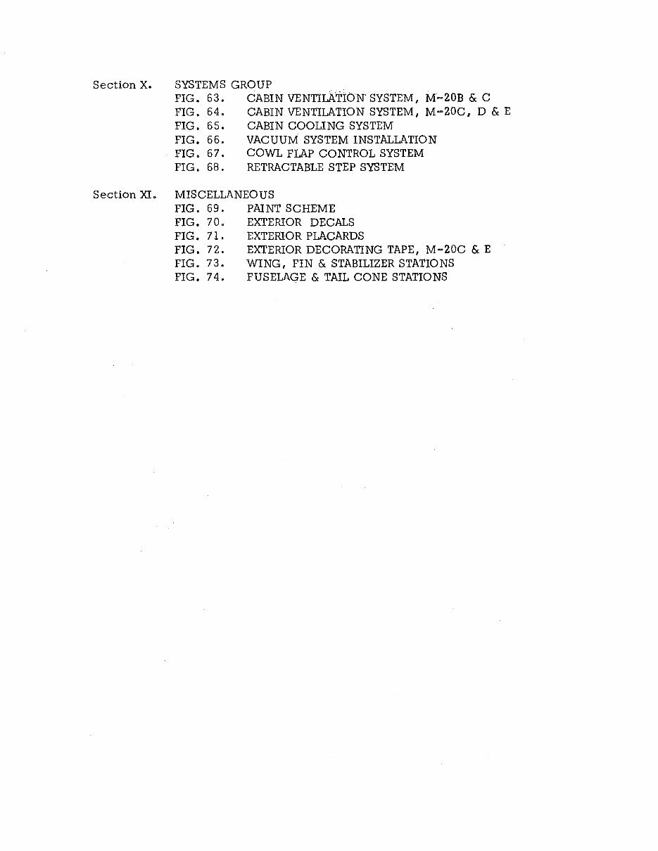
Section X. SYSTEMS GROUP
FIG. 63.
FIG. 64.
FIG. 65.
FIG. 66.
FIG. 67.
FIG. 68.
CABIN VENTILATION' SYSTEM, M-20B & C
CABIN VENTILATION SYSTEM, M-20C, D & E
CABIN COOLING SYSTEM
VACUUM SYSTEM INSTALLATION
COWL FLAP CONTROL SYSTEM
RETRACTABLE STEP SYSTEM
Section XI. MISCELLANEOUS
FIG. 69. PAINT SCHEME
FIG. 70. EXTERIOR DECALS
FIG. 71. EXTERIOR PLACARDS
FIG. 72. EXTERIOR DECORATING TAPE, M-20C & E
FIG. 73. WING, FIN & STABILIZER STATIONS
FIG. 74. FUSELAGE & TAIL CONE STATIONS
170
183
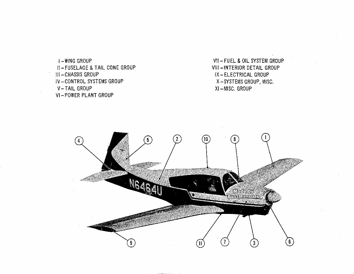
1- WI'NG GROUP
11- FUSELAGE & TAIL CON E GROUP
III-CHASSIS GROUP
IV - CONTROL SYSTEMS GROUP
V- TAIL GROUP
VI-POWER PLANT GROUP
VII- FUEL & OIL SYSTEM GROUP
VIII-INTERIOR DETAIL GROUP
IX - ELECTRICAL GROUP
X-SYSTEMS GROUP, MISC.
XI-MISC. GROUP

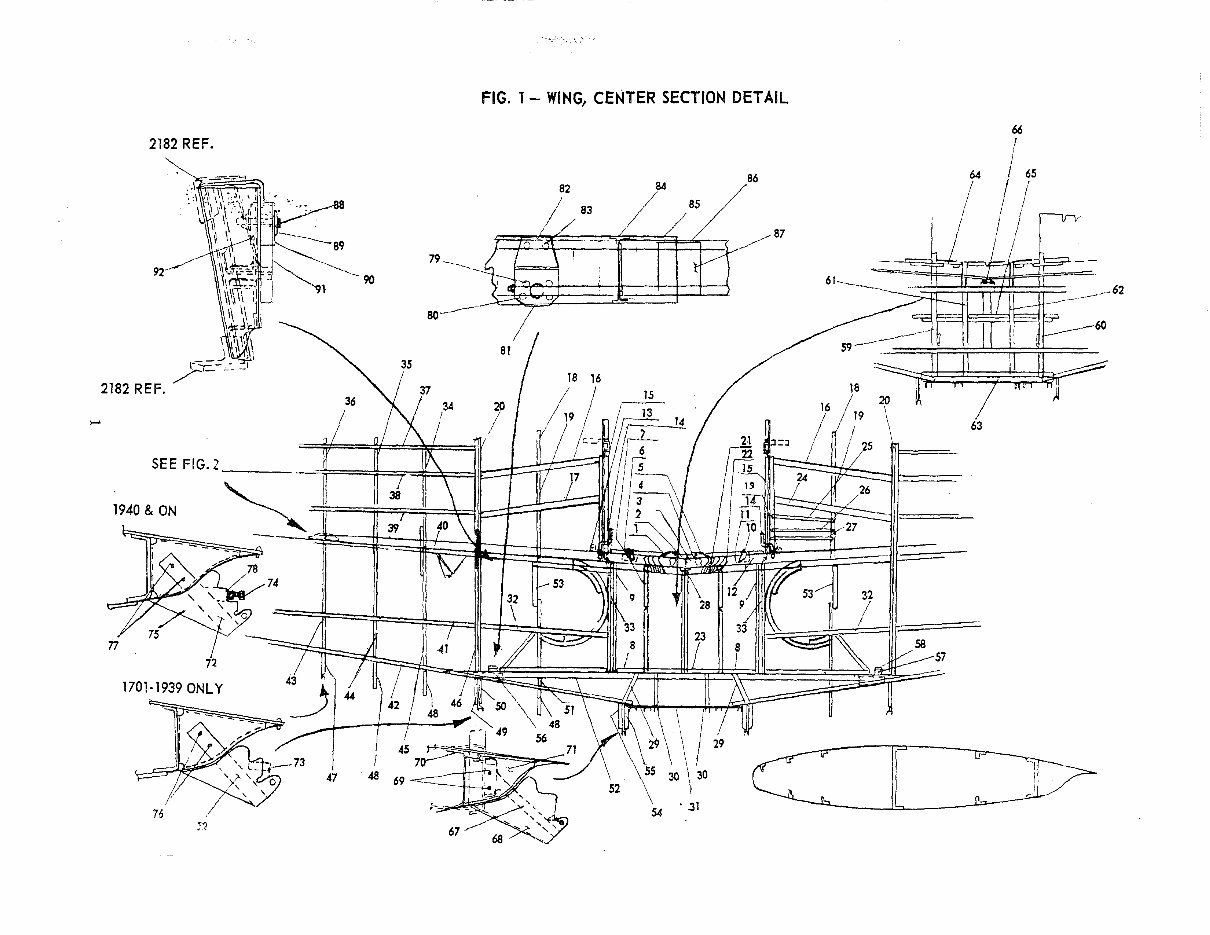
FIG. 1 - WING, CENTER SECTION DETAIL
2182 REF.
88
83
/84 85
86
I 1 ~ I FT=l i---~ 87
JIO ,11,
----..,'--.. 90
80------·
,....
1940 & ON
~2
/
58
57
16
54 '.31
cr-:=r?
47 48 69
:2
67
You're Reading a Preview
What's Included?
Fast Download Speeds
Online & Offline Access
Access PDF Contents & Bookmarks
Full Search Facility
Print one or all pages of your manual
$37.99
Viewed 18 Times Today


Secure transaction
What's Included?
Fast Download Speeds
Online & Offline Access
Access PDF Contents & Bookmarks
Full Search Facility
Print one or all pages of your manual
$37.99
The Mooney M20 1961 B, 1962-64 C, 1963-64 D, 1964 E parts manual is a comprehensive guide consisting of 258 pages. This manual is an invaluable resource for professional mechanics and DIY enthusiasts alike, providing detailed information on the various parts of the aircraft. Whether you are conducting routine maintenance or undertaking repairs, this manual offers the necessary insights to ensure the proper functioning of the Mooney M20 series.


