


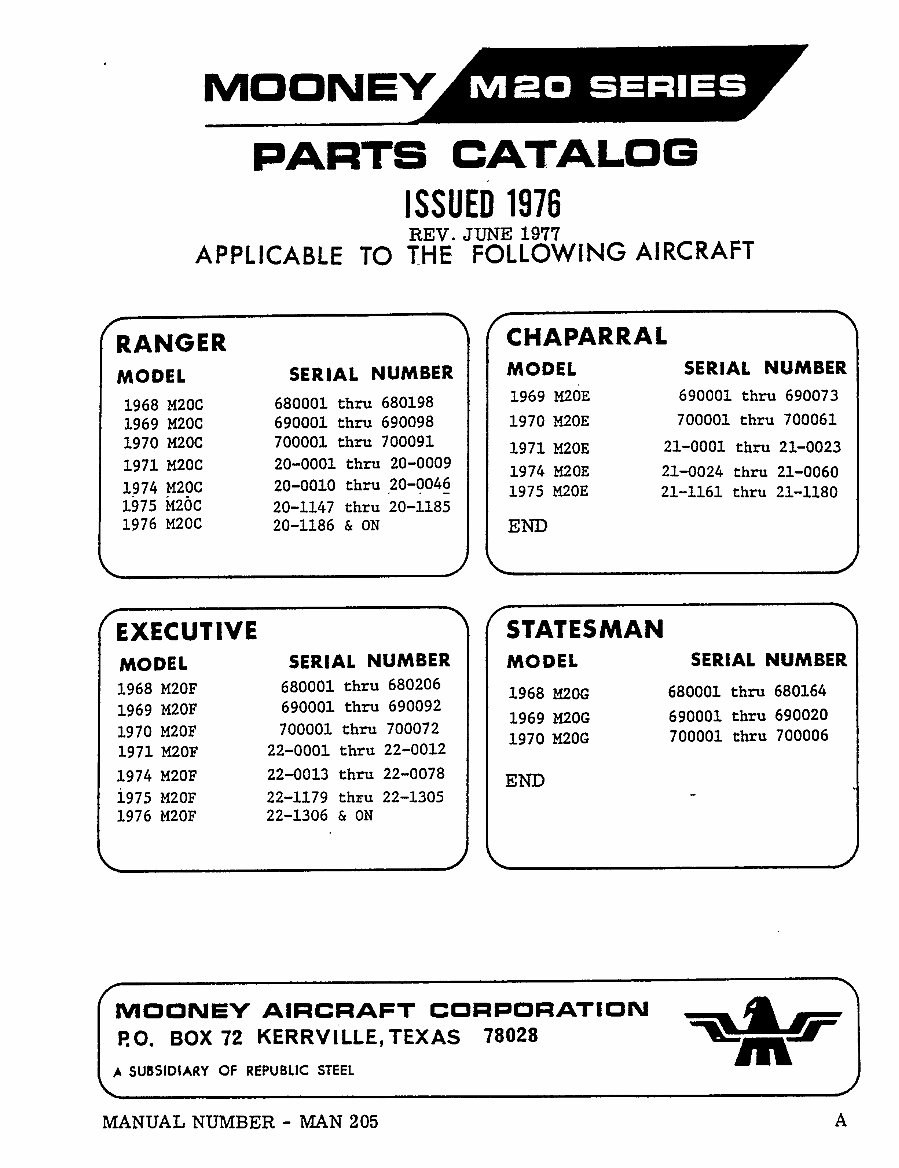
NIO ON EY
PARTS
CATALOG
IssvEo 1976
REV. JUNE 1917
APPLICABLE TO THE FOLLOWING
AIRCRAFT
RANGER ~(CHAPARRAL
MODEL
SERIAL
NUMBER
MODEL SERIAL NUMBER
1968 M20C 680001 thru 680198
1969
M2dE 690001 thru 690073
1969 M20C 690001 thru 690098 1970 M20E 700001 thru 700061
1970 M20C 700001 thru 700091
1971 M20E
21-0001 rhru 21-0023
1971 M20C 20-0001 thru 20-0009
1974 M20E 21-0024 thru 21-0060
1974 M20C
20-0010 thru
?0-004_6
1975 M20E 21-1161 thru 21-1180
1975 20-1147 thru 20-1185
1976 M20C
20-1186 h ON END
EXECUTIVE ~(STATESMAN
MO DE L SERIAL NUMBER MODEL
SERIAL NUMBER
1968 M20F
680001 thru 680206
1968 M20G
680001 thru 680164
1969 M20F
690001 thru 690092
1969 M20G 690001 thtu 690020
1970 M20F
700001 rhru 700072
1970 M20G
700001 thru 700006
1971 M20F 22-0001 thru 22-0012
1974 M20F 22-0013 thru 22-0078
END
i975 M20F 22-1179 thru 22-1305
1976 M20F 22-1306 8 ON
MOONEY AIRCRAFT CORPORATION f~L
P.O. BOX 72 KERRVILLE,TEXAS
78028
SUBSIDIARY OF REPUBLIC STEEL
MANUAL NUMBER MAN 205 A
www.repairmanuals4u.com
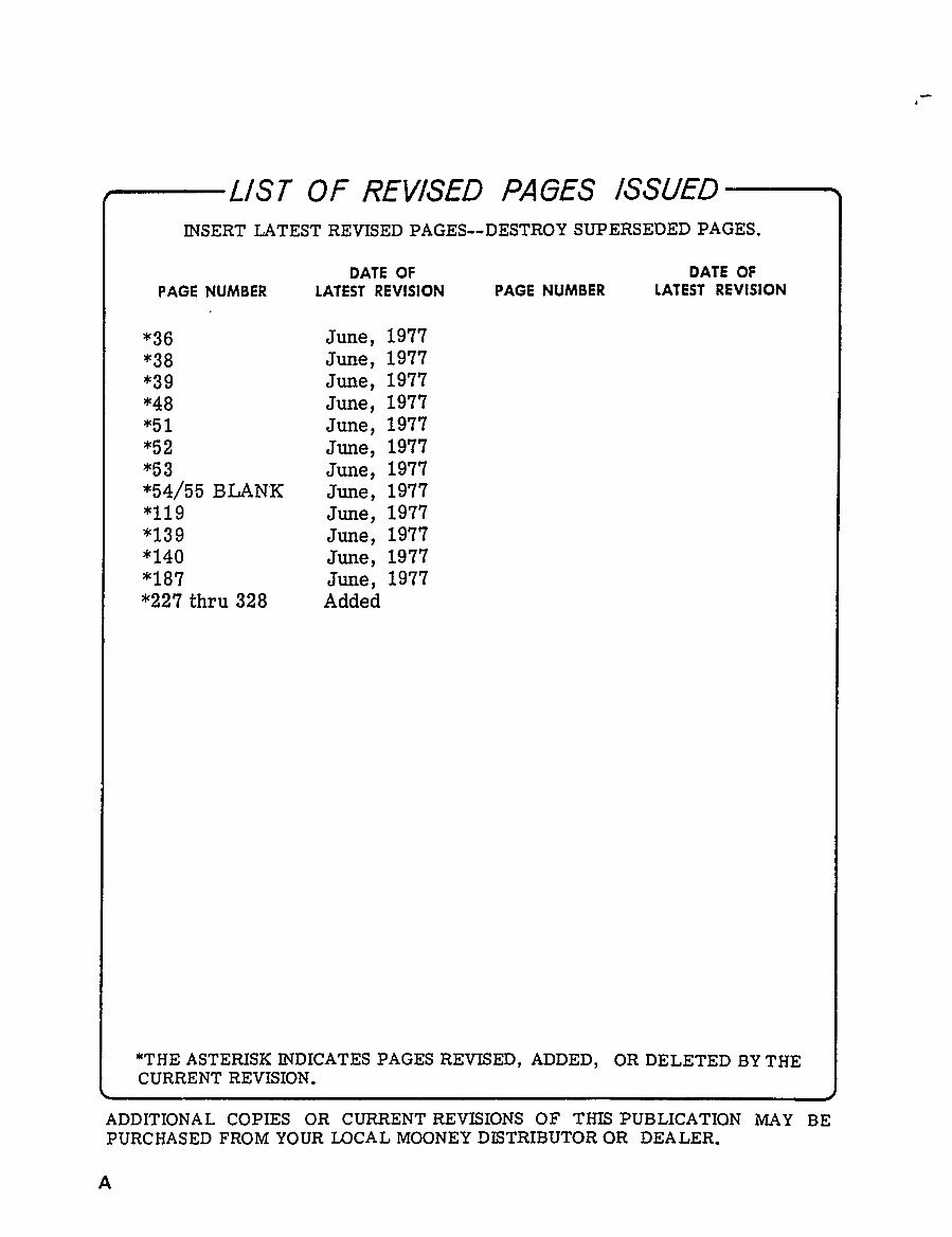
LIST OF REVISED PAGES ISSUED
INSERT LATEST REVISED PAGES--DESTROY SUPERSEDED PAGES.
DATE OF DATE OF
PAGE NUMBER LATEST REVISION PAGE NUMBER LATEST REVISION
"36 June,
1917
*38 June,
1917
"39 June,
1977
*48 June,
1977
*51
June,
1977
*52
June,
1977
*53
June,
1977
"54/55 BLAN~K
June,
1977
*119
June,
1977
"139
June,
1977
"140
June,
1977
*187
June,
1977
*221 thru 328 Added
*THE ASTERISK INDICATES PAGES
REVISED, ADDED, OR DELETED BY THE
CURRENT REVISION.
ADDITIONAL COPIES OR CURRENT REVISIONS OF THIS PUBLICATION MAY BE
PURCHASED FROM YOUR LOCAL MOONEY DISTRIBUTOR OR DEA LER.
www.repairmanuals4u.com
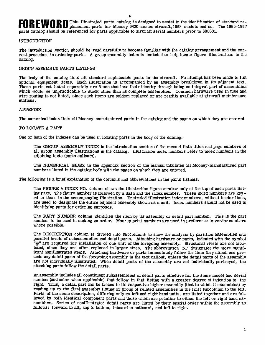
FOREWORD
placement parts
for
Mooney
M20 series
aircraft,
1968 models and
on.This
illustrated
parts catalog
is
designed
to assist in the identification of standard
re-The
1965-1967
parts catalog
should be referenced for
parts applicable
to aircraft serial numbers
prior
to 680001.
INTRODUCTION
The Introduction section should be read
carefully
to become familiar with the
catalog arrangement
and the cor-
rect
procedure
in
ordering parts.
A
group assembly
index is included to
help
locate figure
illustrations in the
catalog.
GROUP ASSEMBLY PARTS LISTINGS
The
body
of the
catalog
lists all standard replaceable parts
in the aircraft. No
attempt
has been made to list
optional equipment
items. Each illustration is
accompanied by an assembly
breakdown in its
adjacent
text.
Those
parts
not listed
separately are items that lose their
identity through being an integral part
of assemblies
which would be
impracticable to stock other than as complete
assemblies. Common hardware used in tube and
wire
routing
is not
listed,
since such items are seldom
replaced or are readily
available at aircraft maintenance
stations.
APPENDIX
The numerical index lists all
Mooney-manufactured parts
in the
catalog
and the
pages
on which
they are entered.
TO LOCATE A PART
One or both of the indexes can be used in
locating parts
in the
body
of the
catalog:
The GROUP ASSEMBLY INDEX in the introduction section of the manual lists titles and
page
numbers of
all
group assembly
illustrations in the
catalog.
Illustration index numbers refer to index numbers in the
adjoining
texts
(parts callouts).
The NUMERICAL INDEX in the
appendix
section of the manual tabulates all Mooney-manufactured part
numbers listed in the
catalog body
with the
pages
on which
they are entered.
The following
is a brief
explanation
of the columns and abbreviations in the
parts listings:
The FIGURE INDEX NO. column shows the illustration
figure
number
only
at the
top
of each
parts
list-
ing page.
The figure
number is followed
by a dash and the index number. These index numbers are key
ed to those in the
accompanying
illustration. Encircled illustration index
numbers,
without leader
lines,
are used to
designate
the entire
adjacent assembly
shown as a unit. Index numbers should not be used in
identifying parts
for
ordering purposes.
The PART NUMBER column identifies the item
by
its
assembly or detail
part
number. This is the
part
number to be used in
making an order.
Mooney print
numbers are used In
preference to vendor numbers
where
possible.
The DESCRIPTION column is divided into subcolumns to show the
analysis by partition
assemblies into
parallel
levels of subassemblies and
detailparts. Attaching hardware or parts,
indented with the
symbol
are
required
for installation of one unit of the
foregoing assembly.
~itructural rivets are not tabu-
lated,
since
they are often
replaced
in
larger sizes. The abbreviation’TJI"
designates
the more signif-
Lcant nonlllustrated Items.
Attaching hardware or parts immediately
follow the item
they
attach and
pre-
cede
any
detail
parts
of the
foregoing assembly
in the text
callout,
unless the detail
parts
of the
assembly
are not
individuallv
illustrated. When detail
parts
of the
assembly are not
individually portrayed,
the
attaching parts follow the detail
parts.
An assernblv includes all constituent subassemblies ordetail
parts
effective for the same model and serial
number land color when
applicable)
that follow in that
listing
with a greater degree
of indention to the
right. Thus, a detail
part can be traced to its
respective higher assembly (that
to which it assembles) by
reading up
to the first
assembly listing or
group
of related assemblies in the first subcolumn to the left.
Parts of the same
description, differing only as left and
right
hand
units, are listed
together
and are fol-
lowed
by
both identical
component parts and those which are peculiar
to either the left or right
hand as-
semblles. Series of nonillustrated detail
parts are listed
by
their
spatial
order within the
assembly as
follows: forward to
aft, top
to
bottom,
inboard to
outboard,
and left to
right.
www.repairmanuals4u.com
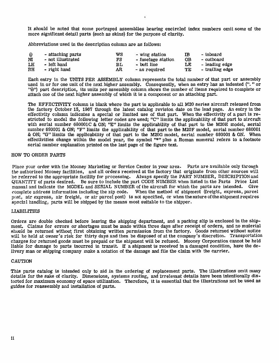
It should be noted that some
portrayed
assemblies
bearing
encircled index numbers omit some of the
more significant detailparts (such as skins)
for the
purpose
of
clarity.
Abbreviations used in the
description
column are as follows:
~2 attaching parts
WS
wing
station IB inboard
NI not illustrated FS
fuselage
station OB outboard
LH left hanci BL butt line LE
leading edge
RH
right
hand AR as required
TE
trailing edge
Each
entry
in the UNITS PER ASSEMBLY column represents
the total number of that part or assembly
used In or for one unit of the next
higher assembly. Consequently,
when an entry
has an indented or
part description,
its units
per assembly
column shows the number of items
required
to
complete
or
attach one of the next higher assembly
of which it is a component or an attaching part.
The EFFECTIVITY column is blank where the
part
is
applicable to all M20 series aircraft released from
the
factory
October
15,
1967
through
the latest
catalog
revision date on the lead
page.
An
entry
in the
effectivity
column indicates a special or limited use of that
part.
When the
effectivity
of a part
is re-
stricted to model the
following
letter codes are used;
"C" limits the
applicability
of that
part
to aircraft
with serial number 680001C
ON;
"E" limits the
applicability
of that
part
to the M20E
model,
serial
number 690001
ON;
"F" limits the
applicability
of that
part
to the M20F
model,
serial number 680001
ON;’%"
limits the
applicability
of that
part
to the M20G
model,
serial number 680001 ON. When
effectivities
change
within the model
year,
the
symbol plus a Roman numeral refers to a footnote
serial number
explanation printed on the last
page
of the
figure
text.
HOW TO ORDER PARTS
Place
your
order with the
Mooney Marketing
or Service Center in
your
area. Parts are available
only through
the authorized
Mooney facilities, and all orders received at the
factory
that
originate
from other sources will
be referred to the
appropriate facility
for
processing. Always specify
the PART
NUMBER,
DESCRIPTION and
QUANTITY of
parts
desired. Be sure to include the
part
CODE NUMBER when listed in the Parts Price List
manual and indicate the MODEL and SERIAL NUMBER of the aircraft for which the
parts
are intended. Give
complete
address information
including
the
zip
code. When the method of
shipment (freight, express, parcel
pust,
air
express,
air
freight,
or air parcelpost)
is not
specified,
or when thenature
oftheshipmentrequires
special handling, parts
will be
shipped by
the means most suitable to the
shipper.
LIABILITIES
Orders are double checked before
leaving
the
shipping department,
and a packing slip
is enclosed in the
ship-
ment. Claims for errors or shortages
must be made within three
days
after receipt
of
orders,
and no material
should be returned without first
obtaining
written
permission
from the
factory.
Goods returned without notice
will be held at owner’s risic for
thirty days
and then be
disposed of at the company’s
discretion. Transportation
charges for returned
goods
must be
prepaid or the
shipment
will be refused.
Mooney Corporation
cannot be held
liable for
damage
to
parts
incurred in transit. If a shipment
is received in a damaged condition,
have the de-
livery man or shipping company
make a notation of the
damage
and file the claim with the carrier.
CAUTION
This
parts catalog
is intended
only
to aid in the
ordering
of
replacement parts.
The illustrations omit
many
details for the sake of
clarity. Dimensions, systems routing,
and irrelevant details have been
intentionally
dis-
torted for maximum
economy
of
space
utilization.
Therefore,
it is essential that the illustrations not be used as
guides
for
reassembly
and installation of
parts.
www.repairmanuals4u.com
GROUP ASSEMBLY INDEX
www.repairmanuals4u.com
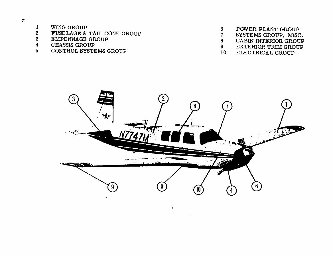
WING GROUP
6 POWER PLANT GROUP
2 FUSELAGE TAIL CONE GROUP
7 SYSTEMS
GROUP,
MISC.
3 EMPENNAGE GROUP
8 CABIN INTERIOR GROUP
4 CHASSIS GROUP
9 EXTERIOR TRIM GROUP
5 CONTROL SYSTEMS GROUP
10 ELECTRICAL GROUP
3
d
2
7~ ~1
~n7, r
t
LMI:~
9) (5
6
10
4
www.repairmanuals4u.com
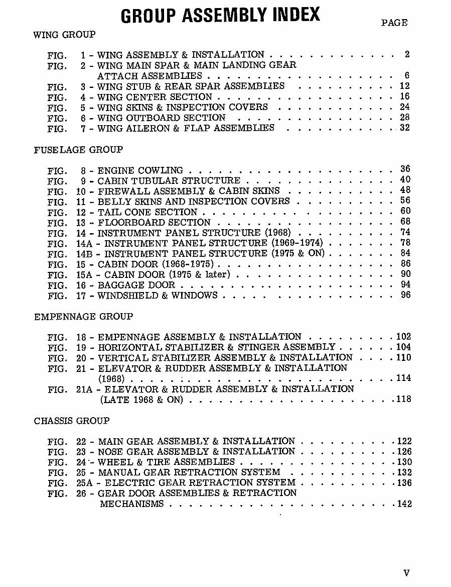
GROUP
ASSEMBLY
INDEX
PAGE
WING GROUP
FIG. 1 WING ASSEMBLY INSTALLATION 2
FIG. 2 WING MAIN SPAR MAIN LANDING GEAR
ATTACH ASSEMBLIES 6
FIG. 3 WING STUB REAR SPAR ASSEMBLIES 12
FIG. 4 WING CENTER SECTION 16
FIG. 5 WING SKINS INSPECTION COVERS 24
FIG. 6 WING OUTBOARD SECTION 28
FIG. 7 WING AILEiRON FLAP ASSEMBLIES ..32
FUSE LAGE GROUP
FIG. 8 ENGINE COWL;ING
36
FIG. 9 CABIN TUBULAR STRUCTURE
40
FIG. 10 FIREWALL ASSEMBLY CABIN SKINS
48
FIG. 11 BELLY SKINS AND INSPECTION COVERS
56
FIG. 12 TAIL CONE SECTION
60
FIG. 13 FLOORBOARD SECTION
68
FIG. 14 INSTRUMENT PANEL STRUCTURE (1968)
74
FIG. 14A INSTRUMENT PANEL STRUCTURE (1969-1974)
78
FIG. 14B INSTRUMENT PANEL STRUCTURE (1975 ON)
84
FIG. 15 CABINDOOR (1968-1975)
86
FIG. 15A CABIN DOOR (1975 later)
90
FIG. 16 BAGGAGE DOOR 94
FIG. 17 WINDSHIELD WINDOWS ~96
EMPENNAGE GROUP
FIG. 18 EMPENNAGE ASSEMBLY INSTALLATION 102
FIG. 19 HORIZONTAL STABILIZER STINGER ASSEMBLY 104
FIG. 20 VERTICAL STABILIZER ASSEMBLY INSTALLATION 110
FZG. 21 ELEVATOR RUDDER ASSEMBLY INSTALLATION
(1968).....~
114
FIG. 21A ELEVATOR RUDDER ASSEMBLY INSTALLATION
(LATE
1968
ON)
.118
CHASSIS GROUP
FIG. 22 MAIN GEAR ASSEMBLY INSTALLATION ..........122
FIG. 23 NOSE GEAR ASSEMBLY INSTALLATION ..........126
FTG. 24’- WHEEL TIRE ASSEMBLIES .130
FIG. 25 MANUAL GEAR RETRACTION SYSTEM .132
FIG. 25A ELECTRIC GEAR RETRACTION SYSTEM ..........136
FIG. 26 GEAR DOOR ASSEMBLIES RETRACTION
MECHANISMS .142
www.repairmanuals4u.com
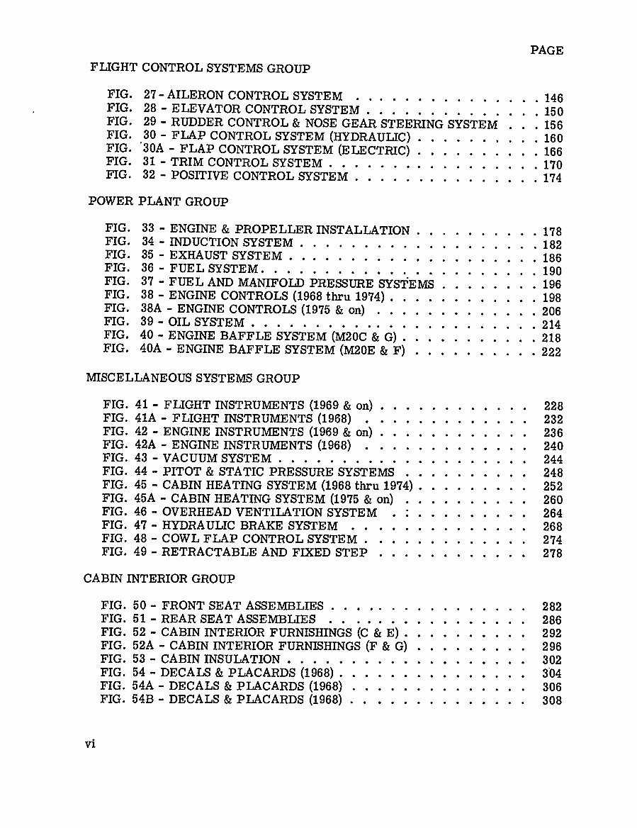
PAGE
FLIGHT CONTROL SYSTEMS GROUP
FIG, 27 AILERON CONTROL SYSTEM
146
FIG, 28 ELEVATOR CONTROLSYSTEM
150
FIG, 29 RUDDER CONTROL NOSE GEAR STEERING SYSTEM 156
FIG, 30 FLAP CONTROL SYSTEM
(KYDRAULIC) 160
FIG, ’30A FLAP
CONTROLSYSTEM
(ELECTRIC) 166
FIG. 31 TRIM CONTROL SYSTEM
170
FIG, 32
POS~IVE CONTROL SYSTEM
174
POWER PLANT GROUP
FIG, 33 ENGINE PROPELLER INSTALLATION
178
FIG, 34
INDUCTIONSYSTEM
182
FIG, 35 EXHAUST SYSTEM
186
FIG, 36-FUELSYSTEM.
.,..,,,,.,,,,,,_
190
FIG, 37 FUEL AND MANIFOLD PRESSURE SYST‘EMS 196
FIG. 38 ENGINE CONTROLS
(1968thru 1974)............ 198
FIG, 38A ENGINE CONTROLS (1975 on) 206
FIG, 39 OIL SYSTEM
214
FIG. 40 ENGINE BAFFLE SYSTEM
(M20C G) 218
FIG, 40A ENGINE BAFFLE SYSTEM (M20E Fl 222
MISCELLANEOUS SYSTEMS GROUP
FIG, 41 FLIGHT INSTRUMENTS (1969 on) 228
FIG, 41A FLIGHT INSTRUMENTS
(1968) 232
FIG, 42 ENGINE INSTRUMENTS (1969 oIj
236
FIG, 42A ENGINE INSTRUMENTS
(1968) 240
FIG, 43 VACUUMSYSTEM
244
FIG, 44 PITOT STATIC PRESSURE SYSTEMS 248
FIG, 45 CABIN HEATING SYSTEM
(1968 thru
1974) 252
FIG, 45A CABIN HEATING SYSTEM
(1975 on) 260
FIG, 46 OVERHEAD VENTILATION SYSTEM 264
FIG, 47 HYDRAULIC BRAKE SYSTEM 268
FIG, 48 COWL FLAP CONTROL SYSTEM 274
FIG, 49 RETRACTABLE AND FIXED STEP 278
CABIN INTERIOR GROUP
FIG, 50 FRONT SEAT ASSEMBLIES 282
FIG, 51 REAR SEAT ASSEMBLIES
286
FIG, 52 CABININTERIOR FURNISHINGS (C E) 292
FIG, 52A CABIN INTERIOR FURNISHINGS (F G) 296
FIG, 53 CABININSULATION 302
FIG, 54 DECALS PLACARDS
(1968) 304
FIG, 54A DECALS PLACARDS
(1968) 306
FIG, 54B DECALS PLACARDS (1968) 308
vi
www.repairmanuals4u.com
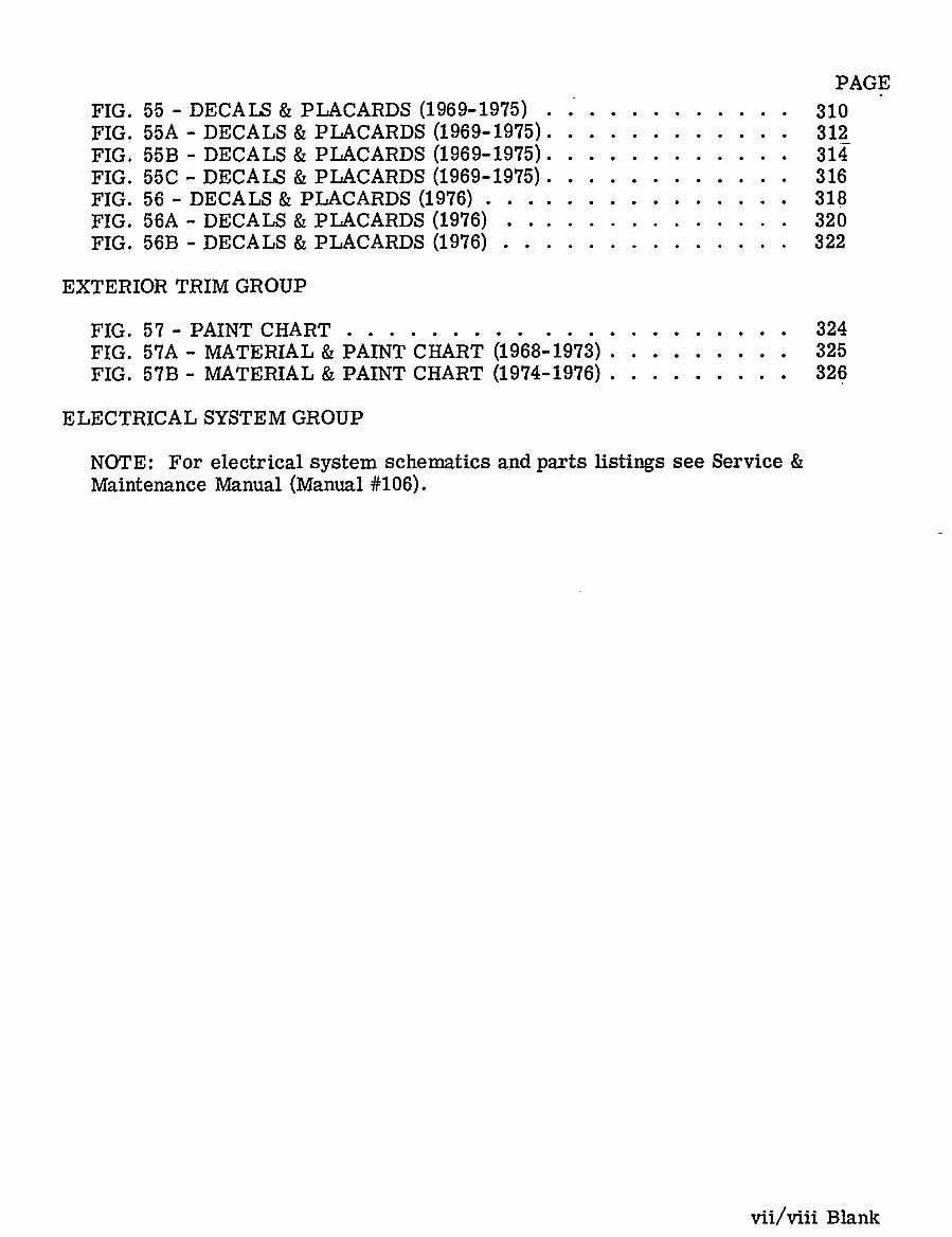
PAGE
FIG. 55 DECALS PLACARDS (1969-1975) 310
FIG;. 55A DECALS PLACARDS (1969-1975). 312
FIG. 55B DECALS PLACARDS (1969-1975). 314
FIG. 55C DECALS PLACARDS (1969-1975). 316
FIG. 56 DECALS PLACARDS (1976)
318
FIG. 56A DECALS PLACARDS (1976)
326
FIG. 56B DECALS PLACARDS (1976)
322
EXTERIOR TRIM GROUP
FIG. 57 PAINT CHART 324
FIG. 57A MATERIAL PAINT CHART (1968-1973)
325
FIG. 57B MATERIAL PAINT CHART
(1974-1916)
326
ELECTRICAL SYSTEM GROUP
NOTE: For electrical
system
schematics and
parts listings
see Service
Maintenance
Manual (Manual #106).
vii/viii Blank
www.repairmanuals4u.com

VVIN G GROUP
www.repairmanuals4u.com
You're Reading a Preview
What's Included?
 Lifetime Access
Fast Download Speeds
Online & Offline Access
Access PDF Contents & Bookmarks
Full Search Facility
Print one or all pages of your manual
$37.99
Mooney aircraft M20C E F G IPC parts manual
Viewed 19 Times Today

What's Included?
Lifetime Access
Fast Download Speeds
Online & Offline Access
Access PDF Contents & Bookmarks
Full Search Facility
Print one or all pages of your manual
$37.99

Secure transaction
What's Included?
Lifetime Access
Fast Download Speeds
Online & Offline Access
Access PDF Contents & Bookmarks
Full Search Facility
Print one or all pages of your manual
The Mooney Aircraft M20C 68-76 E 69-75 F 68-76 G 68 - 70 parts manual, Man #205, is a comprehensive guide for professional mechanics and DIY enthusiasts. This manual spans 297 pages and provides detailed diagrams and information on the various parts of the aircraft. Whether you are conducting routine maintenance or troubleshooting specific issues, this manual serves as a valuable resource for ensuring the proper functioning of the Mooney M20C 68-76 E 69-75 F 68-76 G 68 - 70 aircraft.


