

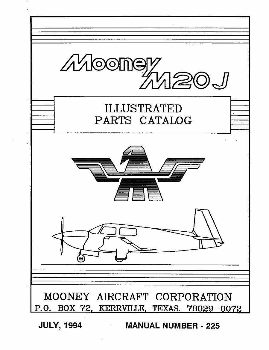
OXO
ILLUSTRATED
PARTS CATALO G
~MO O NE Y AIRC RAFT C O RPO RATIO N
P, O,
RO~ r2, KERRVILI~E, TEXAS. 78029--00753
JULY,
1994 MANUAL NUNIBER 225
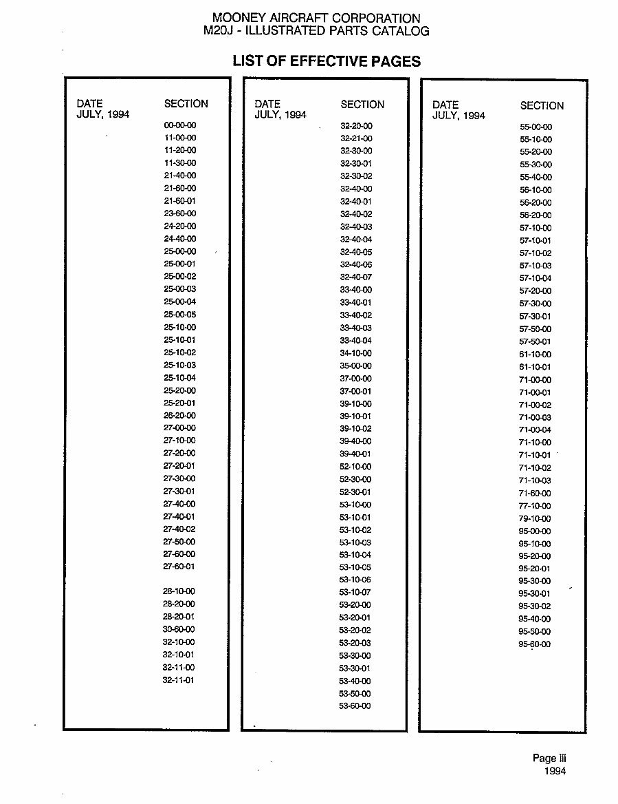
MOONEY AIRCRAFT CORPORATION
M20J ILLUSTRATED PARTS CATALOG
LIST OF EFFECTIVE PAGES
DATE SECTION
I I
DATE SECTION I I DATE SECTION
JULY,1994 I I JULY,1994 I I JULY,1994
00-00-00
I I a~-moo I I 55-00-00
11-00-00
I 1 32-21-00 1 1 55-10-00
11-20-00
I 1 32-30-00 1 1 55-20-00
11-30-00
1 1 32-30-01 1 1 55-30-00
21-40-00
1 1 32-30-02 1 1 55-40-00
21-60-00
I 1 32-40-00 1 1 56-10-00
21-60-01
1 1 32-40-01 1 1 56-20-00
23-60-00
I 1 32-4002 1 1 5620-00
24-20-00
I 1 32-40-03 1 1 57-10-00
24-40-00
I 1 32-40-04 1 1 57-10-01
25-00-00
I 1 32-40-05 1 1 57-10-02
25-00-01
I 1 32-40-06 1 1 57-10-03
25-00-02
1 I 32-40-07 I 1 57-10-04
25-00-03
1 1 33-40-00 1 1 57-20-00
25-00-04
1 1 33-40-01 1 1 57-30-00
25-00-05
1 1 33-4092 1 1 57-30-01
25-10-00
I 1 33-40-03 1 57-50-00
25-10-01
1 1 33-40-04 1 1 57-50-01
25-10-02
1 1 34-10-00 1 1 61-10-00
25-10-03
1 1 35-00-00 i I 61-10-01
25-10-04
1 I 37-00-00 1 71-00-00
25-20-00
I 1 37-00-01 1 I 71-00-01
2520-01
1 1 39-10-00 1 1 71-00-02
26-20-00
1 1 39-10-01 1 1 71-00-03
27-00-00
I 39-10-02 1 1 71-00´•04
27-10-00
I I 39-40-00 I 1 71-10-00
27-20-00
1 1 39-40-01 i I 71-10-01
27-20-01
I 1 52-10-00 i 1 71-10-02
27-30-00
1 I 52-30-00 I 1 71-10-03
27-30-01
1 1 52-30-01 1 I 71-60-00
27-40-00
1 I 53-10-00 I 1 77-10-00
27-40-01
1 53-10-01 I 79-10-00
27-40-02
1 1 53-10-02 1 I 95-00-00
27-50-00
1 1 53-10-03 1 1 95-10-00
27-60-00
I 1 53-10-04 1 1 95-20-00
27-60-01
I 1 53-10-05 1 1 95-20-01
53-10-06
1 1 95-30-00
23-10-00
I 1 53-10-07 1 95-30-01
23-20-00
I 1 53-20-00 1 i 95-30-02
28-mel
I i 53-20-01 i I 95-40-00
30-60-00
I 1 53-20-02 1 1 95-50-00
32-10-00
1 53-20-03 1 1 9560-00
32-10-01 1 1 53-30-00
32-11-00 1 1 53-30-01
32-11-01 1 1 53-40-00
53-50-00
53-69-00
Page
iii
1994
MOONEY AIRCRAFT CORPORATION
M20J ILLUSTRATED PARTS CATALOG
BLANK
Page
iv
1994
MOONEY AIRCRAFT CORPORATION
M20J ILLUSTRATED PARTS CATALOG
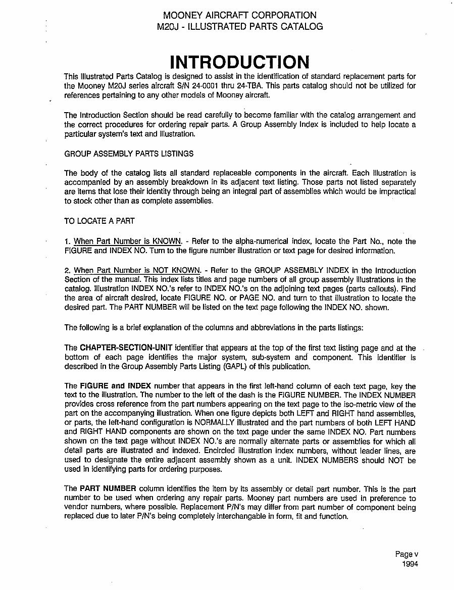
INTRODUCTION
This Illustrated Parts
Catalog
is
designed
to assist in the identification of standard
replacement parts
for
the
Mooney
M20J series aircraft S/N 24-0001 thru 24-TEA. This
parts catalog
should not be utilized for
references
pertaining
to
any
other models of
Mooney
aircraft.
The Introduction Section should be read
carefully
to become familiar with the
catalog arrangement
and
the correct
procedures
for
ordering repair parts.
A
Group Assembly
Index is included to
help
locate a
particular system’s
text and illustration.
GROUP ASSEMBLY PARTS LISTINGS
The
body
of the
catalog
lists all standard
replaceable components
in the aircraft. Each illustration is
accompanied by
an
assembly
breakdown in its
adjacent
text
listing.
Those
parts
not listed
separately
are items that lose their
identity through being
an
integral part
of assemblies which would be
impractical
to stock other than as
complete
assemblies.
TO LOCATE A PART
1. When Part Number is KNOWN. Refer to the
alpha-numerical index, locate the Part
No., note the
FIGURE and INDEX NO. Turn to the
figure
number illustration or text
page
for desired information.
2. When Part Number is NOT KNOWN. Refer to the GROUP ASSEMBLY INDEX in the Introduction
Section of the manual. This index lists titles and
page
numbers of all
group assembly
illustrations in the
catalog.
Illustration INDEX NO.’s refer to INDEX NO.’s on the
adjoining
text
pages (parts callouts).
Find
the area of aircraft desired, locate FIGURE NO. or PAGE NO. and turn to that illustration to locate the
desired
part.
The PART NUMBER will be listed on the text
page following
the INDEX NO. shown.
The
following
is a brief
explanation
of the columns and abbreviations in the
parts listings:
The CHAPTER-SECTION-UNIT identifier that
appears
at the
top
of the first text
listing page
and at the
bottom of each
page
identifies the
major system, sub-system
and
component.
This identifier is
described in the
Group Assembly
Parts
Listing (GAPL)
of this
publication.
The FIGURE and INDEX number that
appears
in the first left-hand column of each text
page, key
the
text to t~he illustration. The number to the left of the dash is the FIGURE NUMBER. The INDEX NUMBER
provides cross reference from the
part
numbers
appearing on the text
page
to the iso-metric view of the
part
on the
accompanying
illustration. When one
figure depicts
both LEFT and RIGHT hand
assemblies,
or
parts,
the left-hand
configuration
is NORMALLY illustrated and the
part
numbers of both LEFT HAND
and RIGHT HAND
components
are shown on the text
page
under the same INDEX NO. Part numbers
shown on the text
page
without INDEX NO.’s are normally
alternate
parts
or assemblies for which all
detail
parts
are illustrated and indexed. Encircled illustration index numbers, without leader
lines, are
used to
designate
the entire
adjacent assembly
shown as a unit. INDEX NUMBERS should NOT be
used in
identifying parts
for
ordering purposes.
The PART NUMBER column identifies the item
by
its
assembly or detail
part
number. This is the
part
number to be used when
ordering any repair parts. Mooney part
numbers are used in
preference
to
vendor numbers, where
possible. Replacement P/N’s
may
differ from
part
number of
component being
replaced
due to later P/N’s being completely interchangable
in form, fit and function.
Pagev
1994
MOONEY AIRCRAFT CORPORATION
M20J ILLUSTRATED PARTS CATALOG
INTRODUCTION
(con~t.)
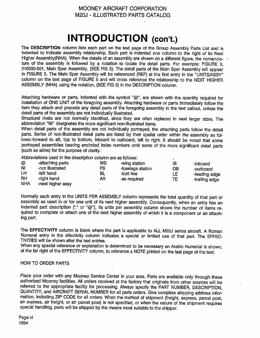
The DESCRIPTION column lists each
part on the text
page
of the
Group Assembly Parts List and is
indented to indicate
assembly relationship.
Each
part
is indented one column to the
right
of its Next
Higher Assembly(NHA).
When the details of an assembly are shown on a different
figure,
the nomencla-
ture of the
assembly
is followed
by a notation to locate the detail
parts.
For
example:
FIGURE
3,
210000-501, Main
Spar Assembly, (SEE
FIG
5).
The detail
parts
of the Main
Spar Assembly
will
appear
in FIGURE 5. The Main
Spar Assembly
will be referenced
(REF)
at the first
entry
in the "UNITS/ASSY"
column on the text
page
of FIGURE 5 and will cross reference the
relationship
to the NEXT HIGHER
ASSEMBLY
(NHA) using
the
notation, (SEE
FIG
3)
in the DESCRIPTION column.
Attaching
hardware or
parts,
indented with the
symbol are shown with the
quantity required
for
installation of ONE UNIT of the
foregoing assembly. Attaching
hardware or
parts immediately
follow the
item
they
attach and
precede any
detail
parts
of the
foregoing assembly
in the text callout, unless the
detail
parts
of the
assembly are not
individually
illustrated.
Structural rivets are not
normally identified, since
they are often
replaced
in next
larger
sizes. The
abbreviation "NI"
designates
the more
significant
non-illustrated items.
When detail
parts
of the
assembly
are not
individually portrayed,
the
attaching parts
follow the detail
parts.
Series of non-illustrated detail
parts
are listed
by
their
spatial
order within the
assembly as fol-
lows:-fonvard to aft, top
to bottom, inboard to outboard, left to
right.
It should´• be noted that some
portrayed
assemblies
bearing
encircled index numbers omit some of the more
significant detail
parts
(such as skins)
for the
purpose
of
clarity.
Abbreviations used in the
description
column are as follows:
-attaching parts
WS
-wing
station IB -inboard
NI -not illustrated FS
-fuselage station OB -outboard
LH -left hand BL -butt line LE
-leading edge
RH
-right
hand AR -as
required TE
-trailing edge
NHA -next
higher assy
Normally
each
entry
in the UNITS PER ASSEMBLY column
represents
the total
quantity
of that
part
or
assembly as used in or for one unit of its next
higher assembly. Consequently,
when an
entry
has an
indented
part description or its units
per assembly
column shows the number of items re-
quired
to
complete or attach one of the next
higher assembly
of which it is a
component or an attach-
ing part.
The EFFECTIVIN column is blank where the
part
is
applicable
to ALL M20J series aircraft. A Roman
Numeral
entry
in the
effectivity
column indicates a
special or limited use of that
part.
The EFFEC-
TIVITIES will be shown after the text entries.
When
any special
reference or
explanation
is determined to be
necessary
an Arabic Numerial is
shown,
at the far
right
of the EFFECTIVITY
column, to reference a NOTE
printed on the last
page
of the text.
HOW TO ORDER PARTS
Place
your
order with
any Mooney
Service Center in
your area. Parts are available
only through
these
authorized
Mooney
facilities. All orders received at the
factory
that
originate
from other sources will be
referred to the
appropriate facility
for
processing. Always specify
the PART
NUMBER, DESCRIPTION,
QUANTIT/, and AIRCRAFT SERIAL NUMBER for all
parts
orders. Give
complete shipping
address infor-
mation, including
ZIP CODE for all orders. When the method of
shipment (freight, express, parcel post,
air
express,
air
freight, or air
parcel post)
is not
specified, or when the nature of the
shipment requires
special handling, parts
will be
shipped by
the means most suitable to the
shipper.
Page
vi
1994
You're Reading a Preview
What's Included?
 Lifetime Access
Fast Download Speeds
Offline Viewing
Access Contents & Bookmarks
Full Search Facility
Print one or all pages of your manual
$41.99
$54.99
Mooney M20J Illustrated Parts Catalog & Service Manual -2- Manuals - IMPROVED -
Viewed 56 Times Today

What's Included?
Lifetime Access
Fast Download Speeds
Offline Viewing
Access Contents & Bookmarks
Full Search Facility
Print one or all pages of your manual
$41.99
$54.99

Secure transaction
What's Included?
Lifetime Access
Fast Download Speeds
Offline Viewing
Access Contents & Bookmarks
Full Search Facility
Print one or all pages of your manual
Description
Fix, maintain, and rebuild your Mooney M20J with the Illustrated Parts Catalog and Service Manual together. This two-manual set gives you exact part numbers, step-by-step maintenance procedures, and detailed diagrams you need to handle everything from routine service to major repairs yourself.
Enhanced with searchable text, bookmarks, and an index, these PDFs are built for instant navigation. Download once, own forever. Start your next M20J project today.


