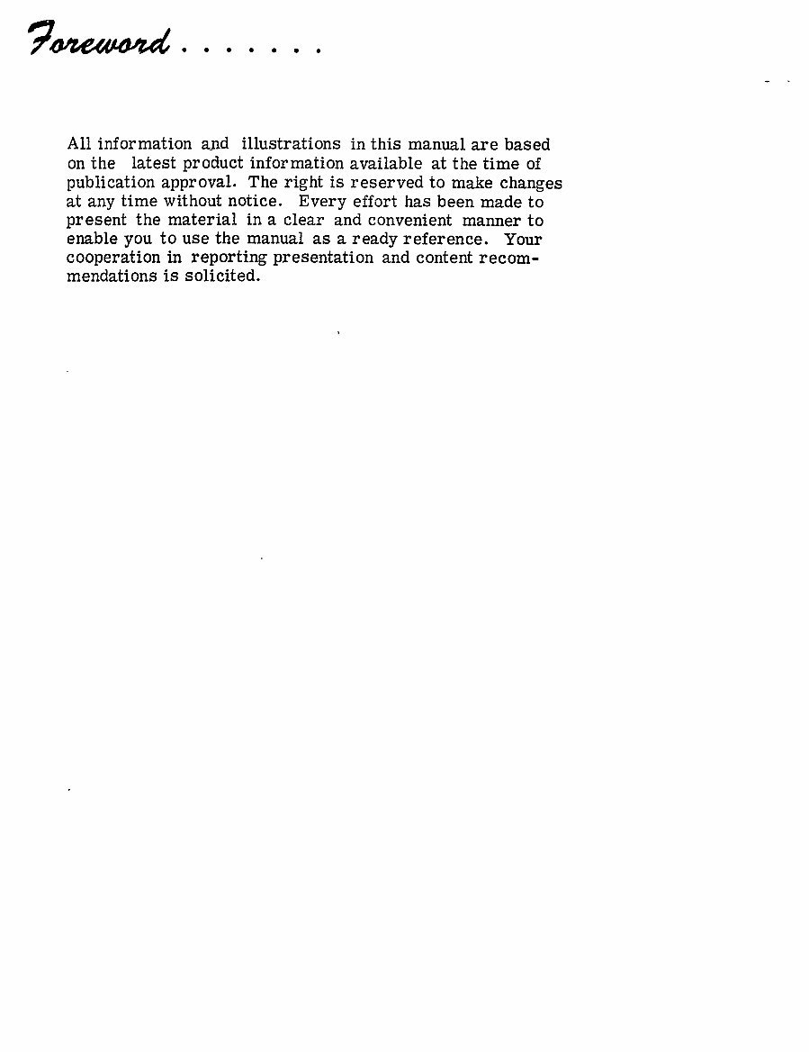
All information and illustrations in this manual are based on the latest product information available at the time of publication approval. The right is reserved to make changes at any time without notice. Every effort has been made to present the material in a clear and convenient manner to enable you to use the manual as a ready reference. Your cooperation in reporting presentation and content recom- mendations is solicited. www.repairmanuals4u.com
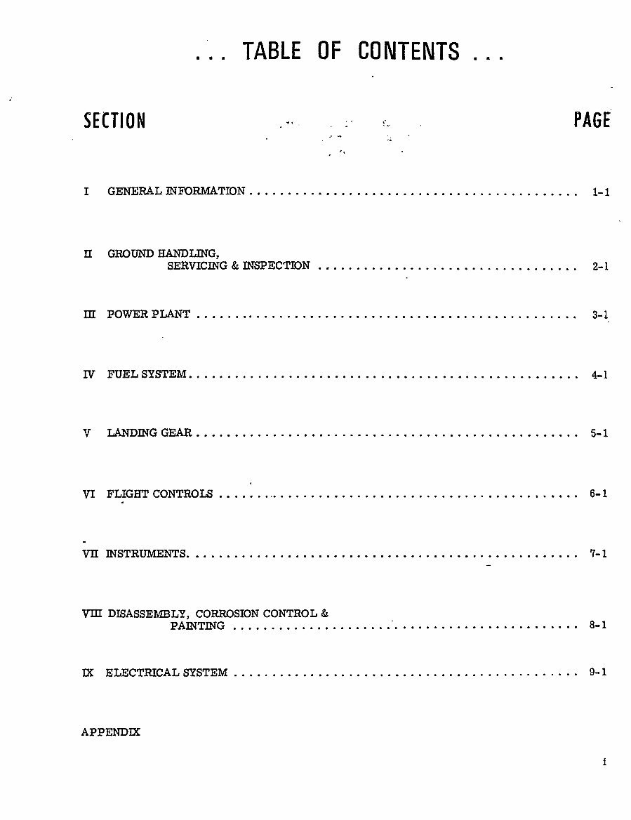
TABLE OF CONTENTS SECTION PAGE I GENERAL INFORMATION 1-1 II GROUND HANDLING, SERVICING INSPECTION 2-1 m POWER PLANT 3-1 IV FUEL SYSTEM. P1 V LANDING GEAR 5-1 VI FLIGHT CONTROLS 6-1 VII INSTRUMENTS. 7-1 wI DISASSEMBLY, CORROSION CONTROL PAINTING 8-1 TX ELECTRICAL SYSTEM 9-1 APPENDM www.repairmanuals4u.com
SECTION GENERAL IN FOR NI AT ION www.repairmanuals4u.com
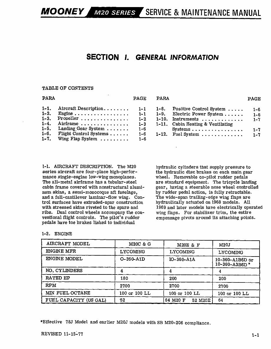
IMOONEY SERVICE IVIAINTENANCE NIANUAL SECTI ON I. GEN~RAL INFORMATION TABLE OF CONTENTS PARA PAGE PARA PAGE 1-1. Aircraft Description........ 1-1 1-8. Positive ControlSystem 1-6 1-2. Engine 1~1 1-9. Electric Power System 1,6 1-3. Propeller 1-2 1-10. Instruments 1-7 1-4. Airframe 1-3 1-11. Cabin Beating Ventilating 1-5. Landing~Gear System 1-6 Systems 1-7 1-6. Flight Control Systems 1-6 1-12. FuelSystem 1-7 1-7. wine; Flap System 1-6 1-1. AIRCRAFT DESCRIPTION. The M20 hydraulic cylinders that supply pressure to series aircraft are four-place high-perfor- the hydraulic disc brakes on each main gear mance single-engine low-wing monoplanes. wheel. Removable co-pilot rudder pedals The all-metal airframe has a tubular-steel are standard equipment. The tricycle landing cabin frame covered with nonstructural alumi- gear, having a steerable nose wheel controlled num skins, a semi-monocoque aft fuselage, by rudder pedal action, is fully retractable. and a full-cantilever laminar-flow wing. Con- The wide-span trailing-edge wing flaps are trol surfaces have extruded-spar construction hydraulically actuated on 1968 models. All with stressed skins riveted to the spars and 1969 and later models have electrically operated ribs. Dual control wheels accompany the con- wing flaps. For stabilizer trim, the entire ventional flight controls. The pilot’s rudder empennage pivots around its attaching points. pedals have toe brakes linked to individual 1-2. ENGME AIRCRAFT MODEL M20C G M20E F M20J ENGINE MFR LYCOMING LYCOMMG LYCOMMG ENGINE MODEL O- 36 ~A1D IO- 36 O-A1A 10-360-A1B6D or 10-360-A3B6D* NO. CYLINDERS 4 4 4 RATED HP 180 200 200 RPM 2700 2700 2700 MTN FUEL OCTANE 100 or 100 LL 100 or 100 LL 100 or 100 LL FUEL CAPACITY (US GAL) ’52 64 M20 F 52 M20E 64 *Effective 785 Model and earlier M20J models with SE M20-206 compliance. REVISED 11-15-77 1-1 www.repairmanuals4u.com
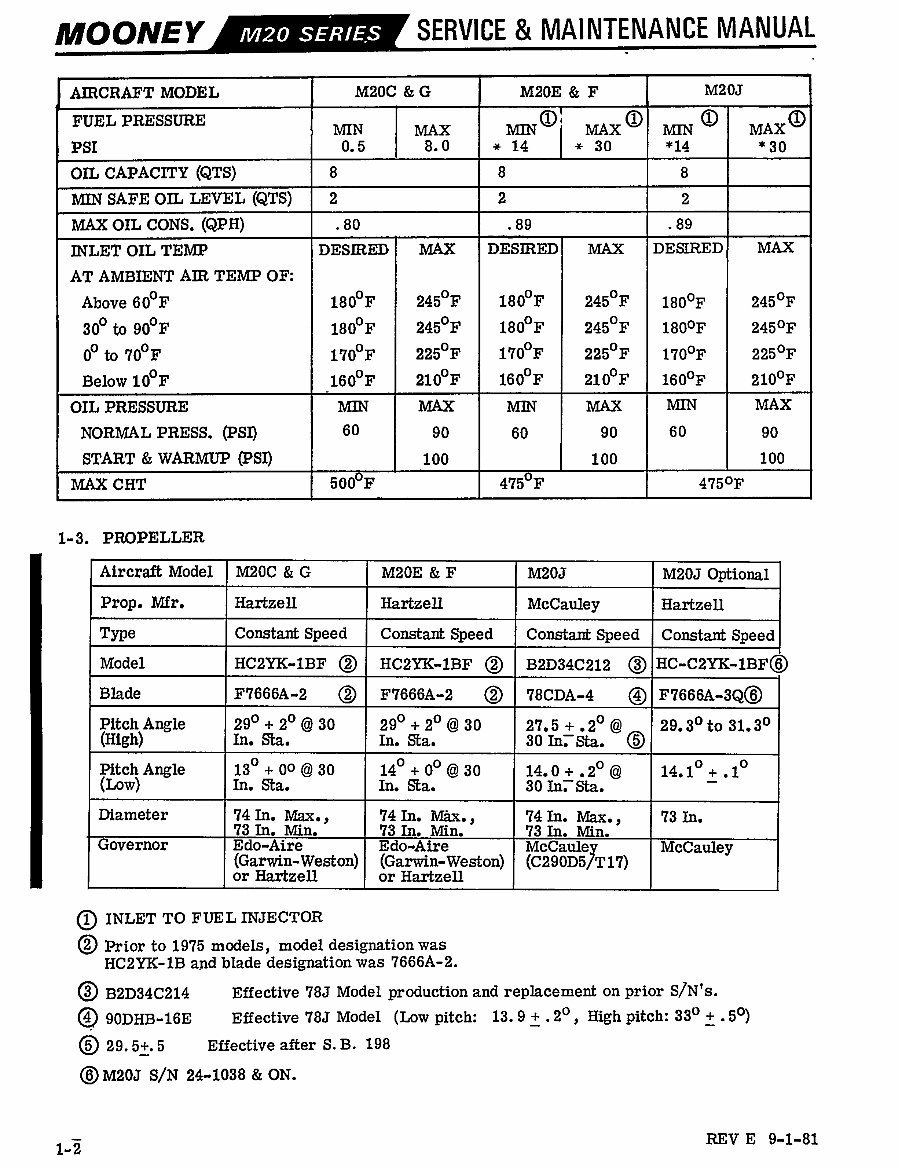
MOONEY SERVICE MAINTENANCE MANUAL AIRCRAFT MODEL M20C G M20E F M20J FUEL PRESSURE 01 O O O MIN MAX MIN MAX MIN MAX PSI 0. 5 8. 0 w 14 w 30 *14 "30 OIL CAPAC~rY (QTS) 8 8 8 MIN SAFE OIL LEVEL (QTS) 2 2 2 MAX OIL CONS. (6~PH) .80 .89 .89 INLET OIL TEMP DESIRED P6AX DESIRED MAX DESIRED MAX AT AMBIENT AIR TEMP OF: Above 600F 1800F 2450F 1800F 2450F 1800F 2450F 300 to 900F 1800F 2450F 1800F 2450F 1800F 2450F oO to 700F 1700F 2250F 1700F 2250F 1700F 2250F Below 100F 1600F 2100F 1600F 2100F 1600F 2100F OIL PRESSURE MIN MAX MIN MAX MIN MAX NORMAL PRESS. (PSI) 60 90 60 90 60 90 START WARMUP $SI) 100 100 100 PUIAX CHT 5 F 4150F 4750F 1-3. PROPELLER Aircraft Model M20C G M20E F M20J M20J Optional Prop. Mfr. Hartzell Hartzell McCauleg Hartzell Type Constant Speed Constant Speed Constant Speed Constant Speed Model HCBYK-1BF O HCBYK-1BF O B2D34C212 OIHC-CBYK-1BF~ Blade F7666A-2 O F7666A-2 O 78CDA-4 Pitch Angle 290 20 30 290 20 30 27. 5 .2" 29. 30 to 31. 30 (High) In. Sta. In. Sta. 30 In,Sta. O Pitch Angle 130 00 30 140 00 30 14. 0 .2" 14. 10 .1" (Low) In. Sta. In. Sta. 30 In,Sta. Diameter 74In. Max., 74In. ~ur., 74In. Max., 73 In. 73In. Min. 73In. Min. 13 In. Min. Governor Edo-Aire Edo-Aire McCaulev McCauley (Garwin-Weston) (Garwin-CYeston) (C290D5JT17) or Hartzell or Hartzell O INLET TO FUEL INJECTOR O Prior to 1975 models, model designation was HCBYK-1B and blade designation was 7666A-2. O B2D34C214 Effective 785 Model production and replacement on prior SjN’s. 90DHB-16E Effective 785 Model (Low pitch: 13. 9 .2", Righ pitch: 330 .5") 0 29. 53´• 5 Effective after S. B. 198 ~M20J S/N 24-1038 ON. REV E 9-1-81 1-2 www.repairmanuals4u.com
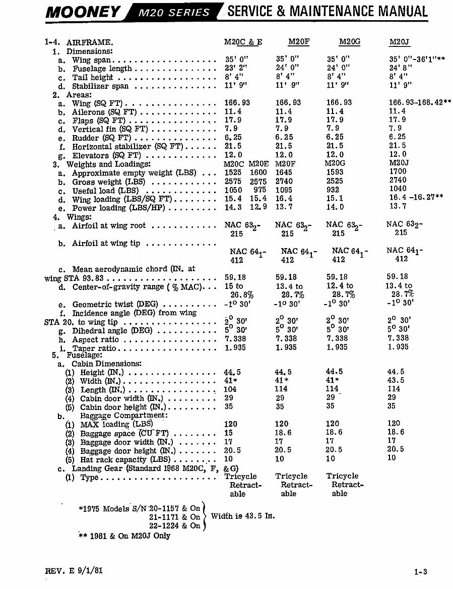
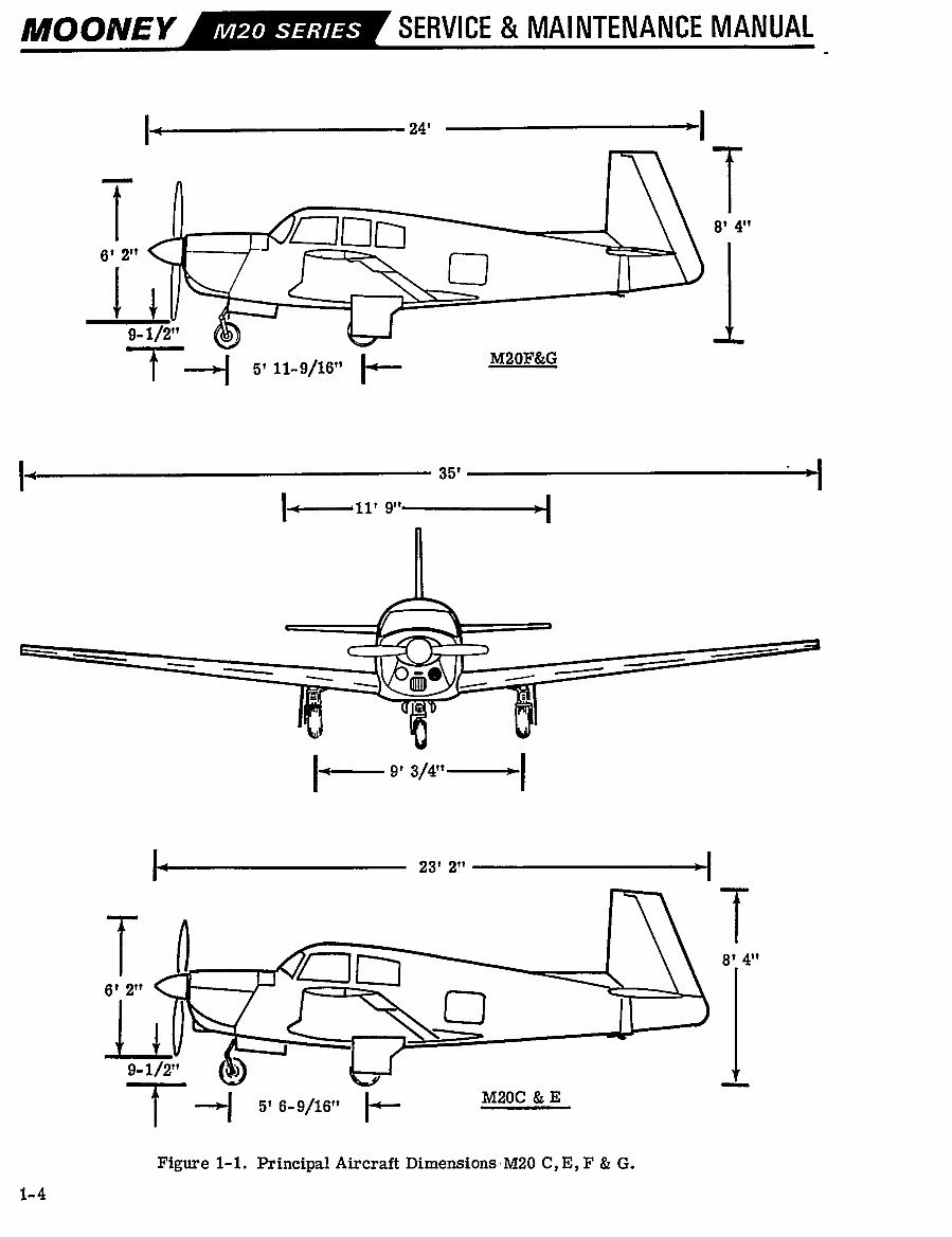
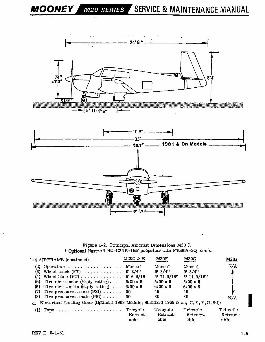
MOONEY SERVICE MAINTENANCE MANUAL 1-4. AIRFRAME. M20~E M20F M20G M20J 1. Dimensions: a. Wing span. 35’ 0" 35’ 0" 35’ 0" 35’ 0"-36’1"** b. Fuselagelength 23’ 2" 24’ 0" 24’ 0" 24’ 8" c. Tail height 8’ 4" 8’ 4" 8’ 4" 8’ 4" d. Stabilizer span 11’ 9" 11’ ´•9" 11’ 9" 11’ 9" 2. Areas: a. Wing(SQFT). 166. 93 166. 93 166. 93 166. 93-168, 42** b. Ailerons (SdZ FT) 11. 4 11.4 11.4 11.4 c. Flaps (SQ FT) 17. 9 17.9 17. 9 17. 9 d. Vertical fin (SQ FT) 7. 9 7. 9 7. 9 7. 9 e. Rudder (SQ FT) 6. 25 6. 25 6. 25 6. 25 f. Horisontal stabilizer (SQ FT)...... 21.5 21.5 21.5 21.5 g. Elevators (SQFT)............. 12. 0 12. 0 12. 0 12. 0 3. Weights and Loadings: M20C M20E M20F M20G M20J a. Approximate empty weight (LBS) 1525 1600 1645 1593 1700 b. Grossweight(LBS) 2575 2575 2740 2525 2740 c. Usefulload(LBS) 1050 975 1095 932 1040 d. Wing 19ading (LBS/SQ FT)......, 15.4 15. 4 16.4 15.1 16. 4 -16.27** e. Powerloading (LBS/HP)......... 14. 3 12. 9 13. 7 14. 0 13.7 4, Wings: a. Airfoilatwingroot NAC 632- NAC 632- NAC 632- NAC 632- 215 215 215 215 b. Airfoilatwingtip 1- NAC 641’ NA(3 641- NAC 641- NAC 64 412 412 412 412 c. Mean aerodynamic chord (IN. at wing STA 93. 83 59.18 59.18 59.18 59.18 d. Center-of-gravity range (o~ MAC)... 15 to 13.4 to 12. 4 to 13.4 to 26.8~’0 28.7Yo 28.7~’0 28.70/e e. Geometrictwist -1030’ -lo 30’ -10 30’ -10 30’ f. Ii~cidence angle @EG) from wing STA 20, towingtip iO 30’ 20 30’ 20 30’ 20 30’ g. Dihedralangle @EG) 5O 30’ 50 30’ 50 30’ 50 30’ h. Aspect ratio 7. 338 7. 338 7. 338 7. 338 i. Taper ratio 1. 935 1. 935 1. 935 i. 935 5. Fuselage: a. Cabin Dimensions: (1) Height (IN,) 44.5 44. 5 44.5 44. 5 (2) Width 41* 41* 41* 43.5 (3) Length ~T.) 104 114 114 114 (4) Cabin door width (IN,) 29 29 29 29 (5) Cabin door height 35 35 35 35 b. Baggage Compartment: (i) MAXloading (LBS) 120 120 120 120 (2) Baggage 15 18. 6 18.6 18. 6 (3) Baggage door width ~N.) 17 17 17 17 (4) Baggage door height 20. 5 20. 5 20. 5 20. 5 (5) H$t rack capacity (LBS) 10 10 10 10 c. Landing Gear (Standard 1968 M20C, F, &G) (1) Type Tricycle Tricycle Tricycle Retract- Retract- Retract- able able able I Width is 43.5 Irt. *1975 Models S/N’20-1157 On 21-1171& On 22-1224 On 1981 On M20J Only REV. E 9/1/81 1-3 www.repairmanuals4u.com
IMOO~VEY SERVICE MAINIENANCE MANUAL 1- 24’ -1 T ~nrs 8’ 4" e, 2"1~s- 1/2" 1 I i -f--;l 5’ 11-9/16" Ic M20~ 11 95’ -1 1~- 9´• 1~ 23’ 2" -1 f 5 71~1 8’ 4" 2" LL O 9- 1/2" -f --c( 5’ 6-9/16" 1L M20~ Figure 1-1. mcincipal Aircraft DimensionsM20 C,E,F G. 1-4 www.repairmanuals4u.com
IMOONEY SERVICE MAINTENANCE MANUAL 74" ~\8’4 *73’ 5’11-9/16 I i-´•´• I9"-------~1 I, 1981 i On Model´• -1 Figure 1-2. Principal Aircraft Dimensions M20 J. Optional Hartzell IIC-C2YK-1BF propeller with F7666A-3Q blade. 1-4 AIRFRAME (continued) M20C E M20F MZOG M20J (2) Operation Manual Manual Manual N/A (3) Wheeltrack(FT) 9’ 3/4" 9’ 3/4" 9’ 3/4" (4) Wheelbase (FT) 5’ 6 9j16 5’ 11 9~’16" 5’ 11 9/16" (5) Tire size--nose (9-pig rating)....’’’ 5: 00 x 5 5:00 x 5 5:00 x 5 (6) Tire size--main (6-ply rating) 6: 00 x 6 6: 00 x 6 6: 00 x 6 (7) Tire pressure--nose CPSI) 30 49 49 (8) Tire pressure--main (PSI) 30 30 30 N/A d. Electrical Tanrlinp Gear (Optional 1968 Models; Standard 1969 on, C,E,F,C, &J): (1) Type. Tricycle Tricycle Tricycle Tricydle Retract- Retract- Retract- Retract- able able able able REV E 9-1-81 1-5 www.repairmanuals4u.com
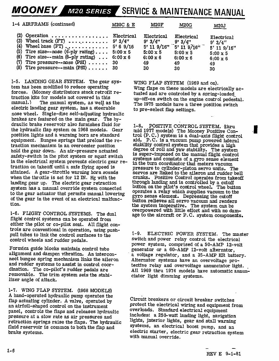
MoonrEv SERVICE MAINTENANCE MANUAL 1-4 AIRFRAME (continued) M20C E M20F M20G M20j (2) Operation Electrical Electrical Electrical Electrical (3) Wheeltrack(FT) 9’ 3/4" 9’ 3/4" 9’ 3/4" 91 3/4" (4) wheelbase (FT) 5’ 6 9/16 5’119/18" 5’ 11 9/16" (5) Tire size-nose (6´•ply rating).... 5:00 x 5 5:00 x 5 5: 00 x 5 5:00 x 5 (6) Tire size--main ~-ply rating) 6: 00 x 6 6: 00 x 6 6: 00 x 6 6:00 x 6 (1) Tire pressure--nose ~SI) 30 49 49 49 (8) Tire pressure--main (PSI) 30 30 30 30 1-5. LANDING GEAR SYSTEM. The gear sys- WING FLAP SYSTEM (1969 and on). tem has been modified to reduce operating Firing flaps on these models are electrically ac- forces. (Mooney distributors stock retrofit re- tuated and are controled by a spring-loaded traction kits for models not covered in this up-off-an switch on the engine control pedestal. manual.) The manual system, as well, as the The 1975 models have a three position switch electric Ianding gear system, has a ste~rable to pre-select flap settings. nose wheel. Single-disc self-adjusting hydraulic brakes are featured on the main gear. The hy- draulic brake reservoir also furnishes fluid for 1-8. POSPTIVE CONTROL SYSTEM. ehru ´•I The Mooney position lights and a warning horn are standard trol (P. C.) system is a dual-axis flight control equipment. Bungee springs that preload the re- aid. P. C. is a vacuum pump powered lateral traction mechanism in an overcenter position stability control system that provides a high hold the gear down. An air-pressure actuated degree of roll and yaw stability. The system safety-switch in the pitot system or squat switch is super-imposed on the manualflight control systems and consists of a ggro sense element in the electrical system prevents electric gear re- in the turn coordinator that meters vacuum traction on takeoff until a safe flying speed is pressure to cylinder-piston servo units. The attained. A gear-throttle warning horn sounds servos are linked to the aileron and rudder bell when the throttle is set for 12 IN. I´•Ig with the cranks. Positive Control operates from takeoff landing gear up. The electric gear retraction through landing and is controlled by a c~rtaff system has a manual override system connected button on the pilot s controlwheel, The button to the gear actuator that permits manual lowering operates a relay which supplies vacuum to the gyro sense element, Depressing the cutoff of the gear in the event of an electrical malfunc- button relieves all servo vacuum and renders tion. the system inoperative. The system can be overpowered with little effort and with no dam- 1-6. FLlGIlT CONTROL SYSTEMS. The dual age to the aircraft or P.C. system components, night control systems can be operated from either the pilot or co-pilot seat. Allflight con- trols are conventional in operation, using push- pull tubes to link the control surfaces to the 1-9. ELECTRIC POm’ER SYSTEM. The master control wheels and rudder pedals. switch and power relay control the electrical power system, comprised of a 50-AMP 12-volt Formica guide blocks maintain control tube generator or a 60-AMP la-volt alternator, alignment and dampen vibration. An intercon- a voltage regulator, and a 35-AMP tIR battery. nect bungee spring mechanism links the aileron Alternator systems have an overvoltage pro- and rudder systems to assist in control coor- tective relay and overvoltage annunciator light. dination. The co-pilot‘’s rudder pedals are All 1969 thru 1974 models have automatic annun- removable. The trim system sets the stabi- ciator light dimming systems. lizer angle of attack. 1-7. WING FLAP SYSTEM. (1968 MODELS) A hand-operated hydraulic pump operates the Circuit breakers or circuit breaker switches flap actuatir~ cylinder. A valve, operated by an airfoil-shaped control on the instrument protect the electrical wiring and equipment from panel, controls the flaps and releases hydraulic Overloads. Standard electrical equipment pressure at a slow rate as air pressures and includes: a 250-watt landing light, navigation retraction springs raise the flaps. The hydraulic lights, interior lights, gear and stall warning fluid reservoir is common to both the flap and SSstems, an electrical boost pump, and an brake systems. ele~tric starter, electric gear retraction system with manual override. 1~B REV E 9-1-81 www.repairmanuals4u.com
This complete Factory Mooney Executive M20F 1968-1976 Service and Maintenance Manual provides essential instructions for maintaining and servicing your Mooney Aircraft using detailed diagrams and manufacturer specifications.
The Manual covers the following Years, Models, and Serial Numbers:
1968 - M20F - 680001 thru 680206
1969 - M20F - 690001 thru 690092
1970 - M20F - 700001 thru 700072
1971 - M20F - 22-0001 thru 22-0012
1974 - M20F - 22-0013 thru 22-0078
1975 - M20F - 22-1179 thru 22-1305
1976 - M20F - 22-1306 thru 22-1438
This improved manual includes bookmarks, searchable text, index, and improved quality.
* INSTANT - NO WAITING
* LANGUAGE: English
* FORMAT: PDF
* COMPATIBLE: All Versions of Windows, Mac, iOS, BB, Android, etc
* PAGES: 291
* SEARCHABLE - BOOKMARKED - INDEXED
This manual is clear and written in a way so that just about anybody can follow it. It is in an easy-to-read PDF file format, viewable on any computer, zoomable, and printable.
Completely searchable & bookmarked, so you can easily find what you are looking for. The ability to search makes finding what you need as easy as typing a word. Zoom it, print it, save it, and close it. Print a few pages at a time or the entire manual. No need to worry about dirty, torn, or missing pages. It has lots of pictures, diagrams, illustrations, and charts. Technical details and instructions you will need are included.
Additional Information: Documents may require the newest version of Acrobat Reader to display correctly. Should you have any problems reading your document, please initially try upgrading to the latest version of Adobe Acrobat Reader. I have Thousands of Aircraft Manuals - email me about any you might need.



 Lifetime Access




