

Mooney M20E Super 21 owners manual
What's Included?
Fast Download Speeds
Online & Offline Access
Access PDF Contents & Bookmarks
Full Search Facility
Print one or all pages of your manual
SUPER 21
MODEL M 20 E
OWNERS
YEAR MODEL SERIAL NUMBERS
196,(
1965
1966
M20E
hUOE
M20E
101-399,
.(70-83-1
832-
1966
OPERATE THIS AIRCRAFT ONLY - 8 after reading
owners manual • with owners manual on board
e after you are fully qualified & understand all of
the aircraft operating characteristics & limitations
MOONEY AIRCRAPT, INC. ...
YEAR
1964
1965
1966
SUPER 2J
OWNERS MANUAL
MODEL
M20E
M20E
M20E
SERIAL NUMBERS
101-399, 401-469
470-831
832-
Revieed Nov. 1965
Thank you for choosing a Mooney.
The wisdom of your selection of a Mooney Super 21 will
be proved many times as your hours in this exceptional
airplane increase.
It takes a long time and a lot of flying to appreciate
all of the many outstanding features built into the
Super
This owners manual will help you know your airplane
better and will make your experIence with the Super
21 more enjoyable.
Welcome to the rapidly growing famib' of Mooney or>n-
ers.
MOONEY AIRCRAFT, INC.
KERRVILLE. TEXAS
•
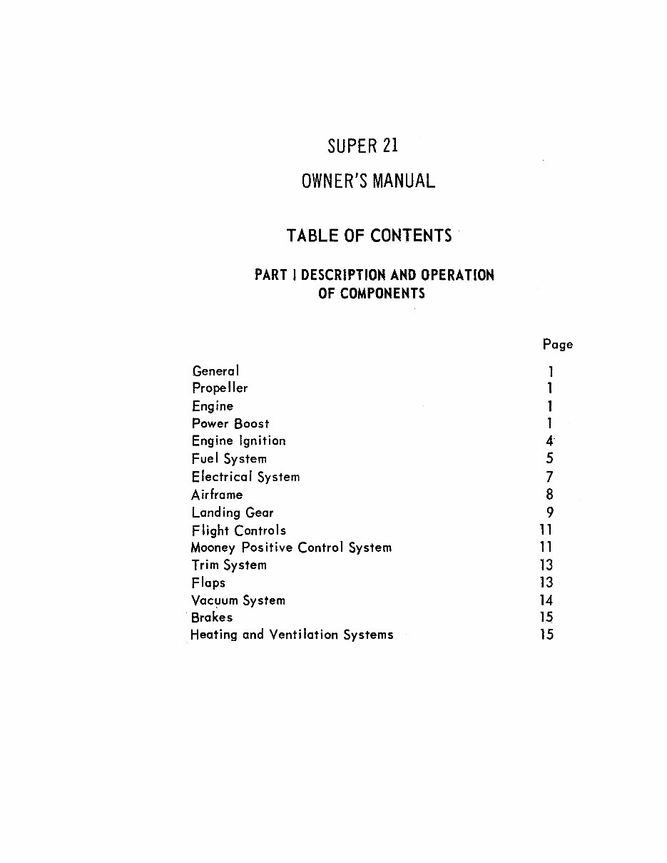
SUPER 21
OWNER'S MANUAL
TABLE OF CONTENTS
PART I DESCRIPTION AND OPERATION
OF COMPONENTS
. General
Propeller
Engine
Power Boost
Engine Ignition
Fuel System
Electrica I System
Airframe
Land ing Gear
F light Controls
Mooney Positive Control System
Trim System
Flaps
Vacl:/um System
. Brakes
Heating and Venti lation Systems
4
Page
1
1
1
1
4-
5
7
8
9
11
11
13
13
14
15
15
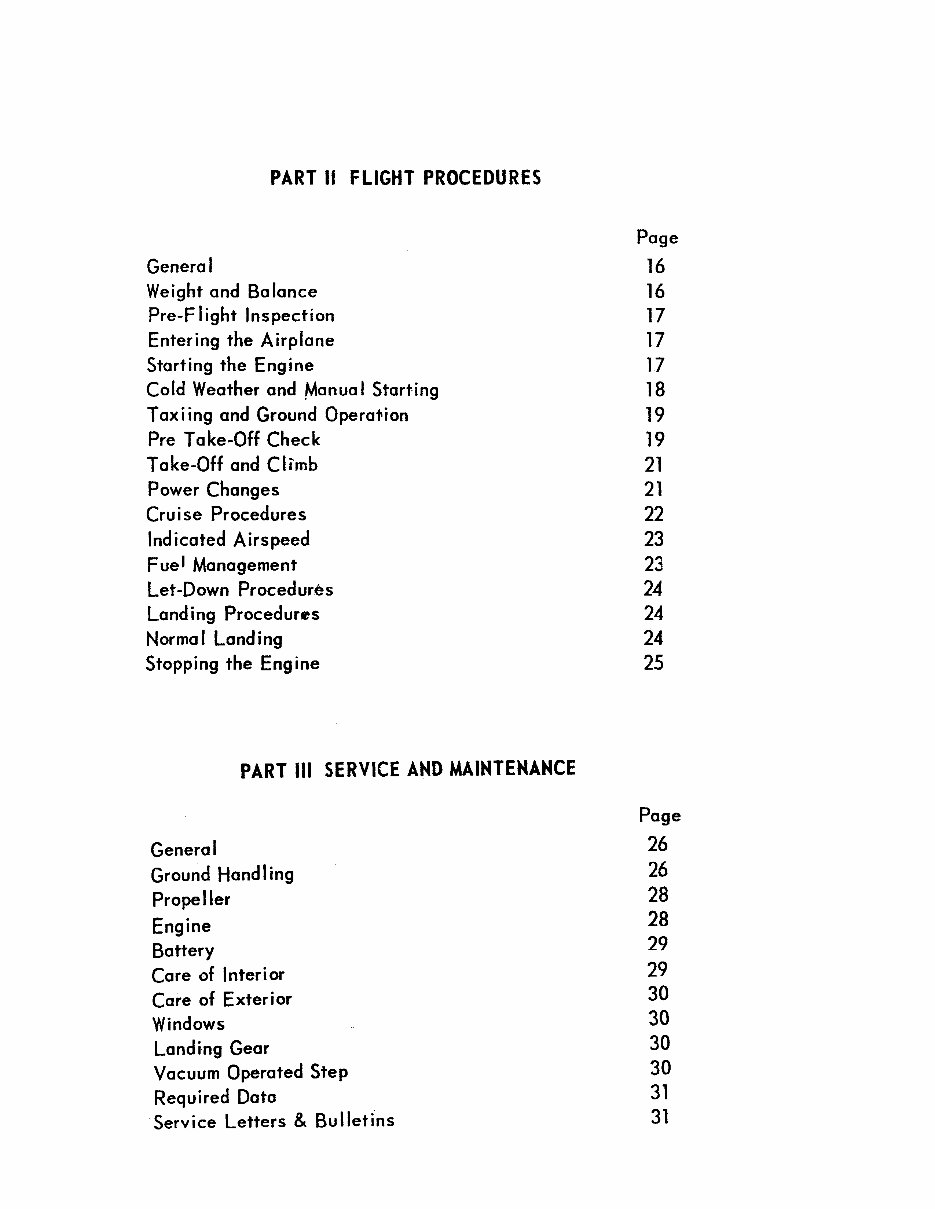
PART II FLIGHT PROCEDURES
General
Weight and Balance
Pre-Flight Inspection
Entering the Airplane
Starting the Engine
Cold Weather and Manua I Start-ing
Tax i ing and Ground Operation
Pre Take-Off Check
Take-Off and Climb
Power Changes
Cru i se Procedures
Indicated Airspeed
F ue J Management
Let-Down Procedures
Landing Procedures
Normal Landing
Stopping the Eng ine
PART III SERVICE AND MAINTENANCE
General
Ground Hand ling
Propeller
Engine
Battery
Care of Interior
Care of Exterior
Windows
Land ing Gear
Vacuum Operated Step
Required Data
Service Letters & Bulletins
Page
16
16
17
17
17
18
19
19
21
21
22
23
23
24
24
24
25
Page
26
26
28
28
29
29
30
30
30
30
31
31
--------------------------
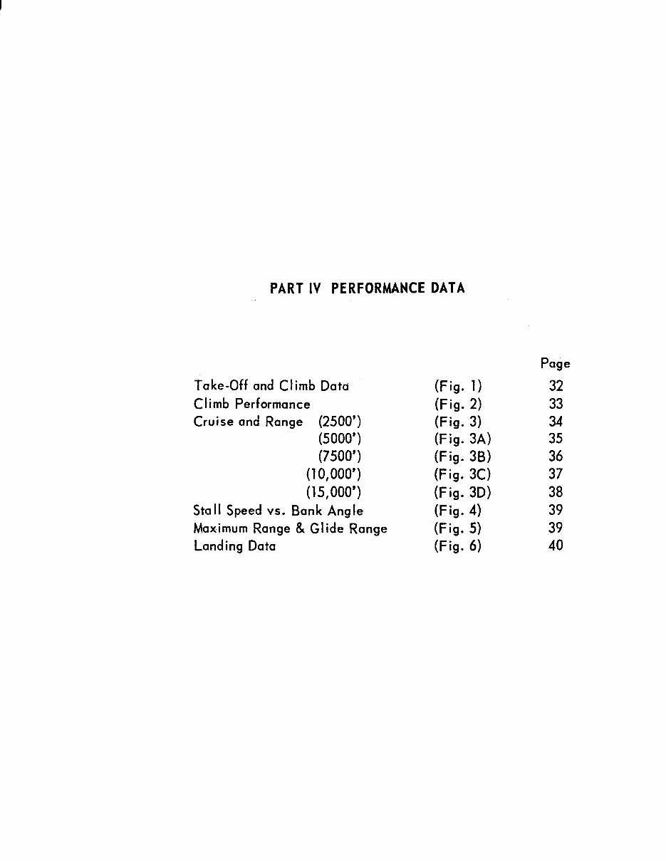
PART IV PERFORMANCE DATA
Take-Off and Climb Data
Climb Performance
Cruise and Range (2500')
(5000')
(7500')
(lO,OOO')
(15,000')
Stall Speed vs. Bank Angle
Maximum Range & Glide Range
Landing Data
4
(Fig. 1)
(F ig. 2)
(Fig. 3)
(Fig. 3A)
(F ig. 3B)
(Fig. 3C)
(Fig. 3D)
(Fig. 4)
(F ig. 5)
(Fig. 6)
Page
32
33
34
35
36
37
38
39
39
40
r .
-
.... -
.. ---
i - '\
\ I
. ..
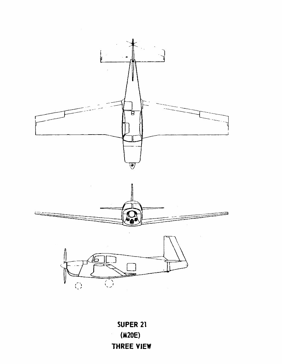
SUPER 21
(M20E)
THREE VIEW
4
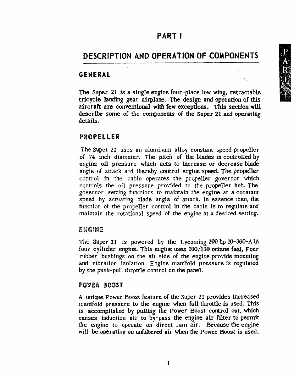
PART I
DESCRIPTION AND OPERATION OF COMPONENTS
GENERAL
The Super 21 is a single engine four-place low wing. retractable
tricycle ]anding gear airplane. The design and operation of this
aircraft are conventional with few excepdons. This section will
describe some of the components of the Super 21 and operating
details.
The Super 21 uses an aluminum alloy constant spee.d propeller
of 74 inch diameter. The pitch of the blades is controlled by
engine oll pressure which acts to increase or decrease blade
angle of attack and thereby control engine speed. The propeller
control in the cabin operates the propeller governor which
controls the oil pressure provided to the propeller hub. The
governor setting functions to maintain the engine at a constant
speed by actuating blade angle of attack. In essence then, the
function of the propeller control in the cabin is to regulate and
maintain the rotational speed of the engine at a desired setting.
The Super 21 is powered by the Lycoming 200 hp IO-360-AIA
four cylinder engine. This engine uses 100/130 octane fuel, Four
rubber bushings on the aft side of the engine provide mourning
and vibration isolation. Engine manifold pressure is regulated
by the push-pull throttle control on the panel.
BOOST
A unique Power Boost feature of the Super 21 provides increased
manifold pressure to the engine when full throttle is used. This
is accomplished by pulling the Power Boost cornrol out. which
causes induction air to by-pass the engine air fUter to permit
the engine to operate on direct ram air. Becaus'! the engine
will be operatinJZ on unfiltered air When the Power Boost is used.
1
•
it should be operated only In clean, duSt free air at altitude, and
turned off for take-off and landing. Because the Power Boost is
effective only when the throttle Is In the fully opened position, -Its
advantages generally wU1 be realized at altitudes above 5,000
feet where night Is often with full throttle. A light 1s provided
on the panel the Power Boost control toremlnd the pDot to
push the control in (to mtered air) before landing. This light
will come on when the gear Is lowered whDe Power Boost is on.
Turn Power Boost off when in icing condi-
tions. Icing conditions prevail any timetbetempera-
ture and moisture conditions combine to produce the
possibility of impact ice.
Using unfnteredlnductlon air when flying In snow or
other IFR conditions can be hazardous. Snow can ac-
cumulate in the fuel InjecJor impact tubes or moisture
can freeze in the passages under icing conditions and
cause loss of power. Therefore It Is imperative
that the Power Boost not be used when flying In
sleet, snow, rain. or moisture-laden air near freez-
Ing temperatures. Under these coooltions Ice can
form in the inlet duct or fuel Injector unit even
though no visible moisture Is on the air-
frame.
2
4
jiii
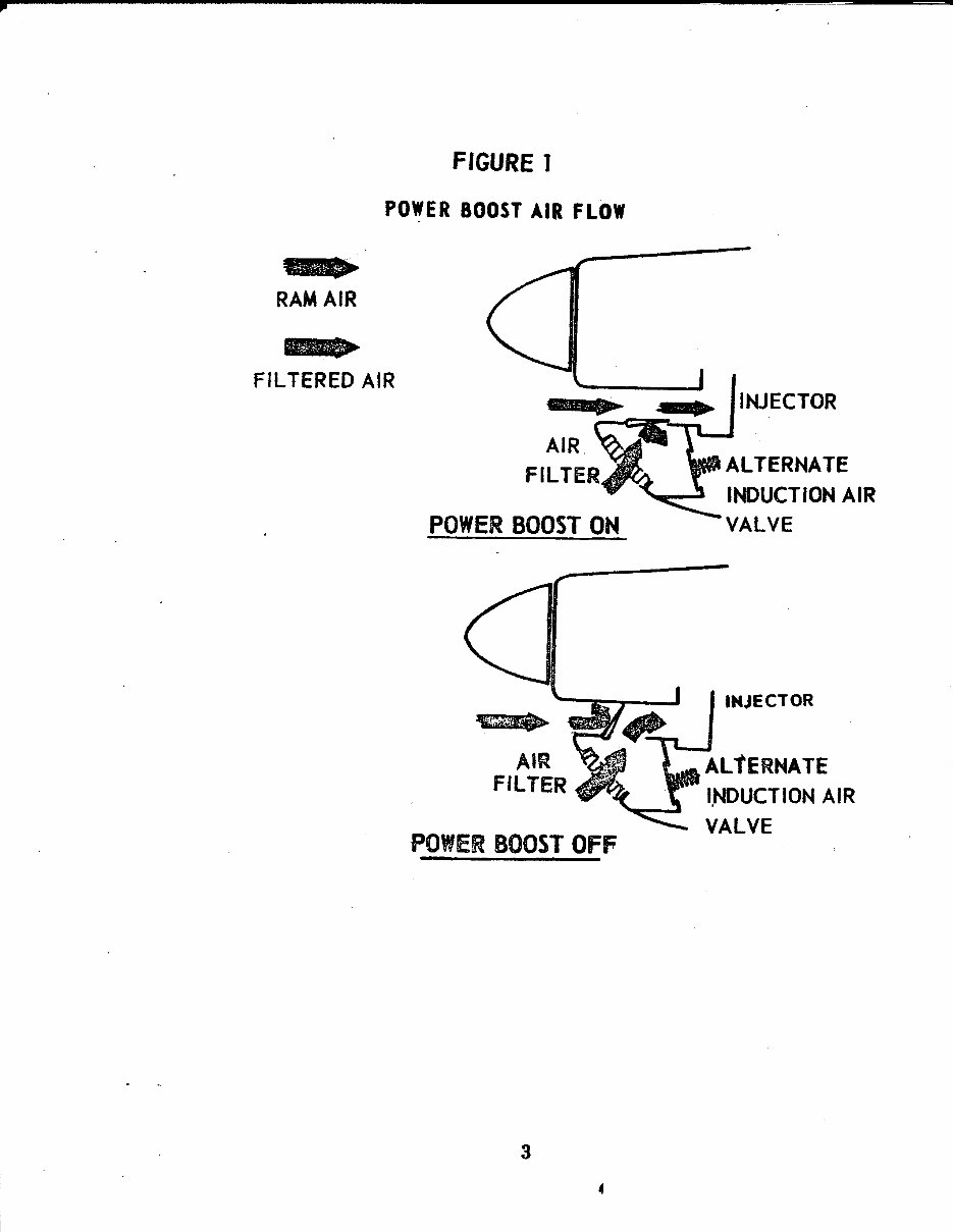
FIGURE 1
POWER BOOST AIR FLOW
....
RAM AIR
....
FILTERED AIR
POWER BOOST ON
AIR
FILTER
POWER BOOST OFF
3
INJECTOR
ALTERNATE
INDUCTION AIR
INJECTOR
ALTERNATE
INDUCTION AIR
VALVE
You're Reading a Preview
What's Included?
Fast Download Speeds
Online & Offline Access
Access PDF Contents & Bookmarks
Full Search Facility
Print one or all pages of your manual
$35.99
Viewed 17 Times Today


Secure transaction
What's Included?
Fast Download Speeds
Online & Offline Access
Access PDF Contents & Bookmarks
Full Search Facility
Print one or all pages of your manual
$35.99
The Mooney M20E Super 21 owners manual from 1964-1966 is a comprehensive guide covering 49 pages of essential information for maintaining and repairing your aircraft. This manual is a valuable resource for both professional mechanics and DIY enthusiasts, providing detailed insights into the technical aspects of the aircraft. Whether you are looking to perform routine maintenance or troubleshoot issues, this manual equips you with the necessary knowledge to keep your Mooney M20E Super 21 in optimal condition.


