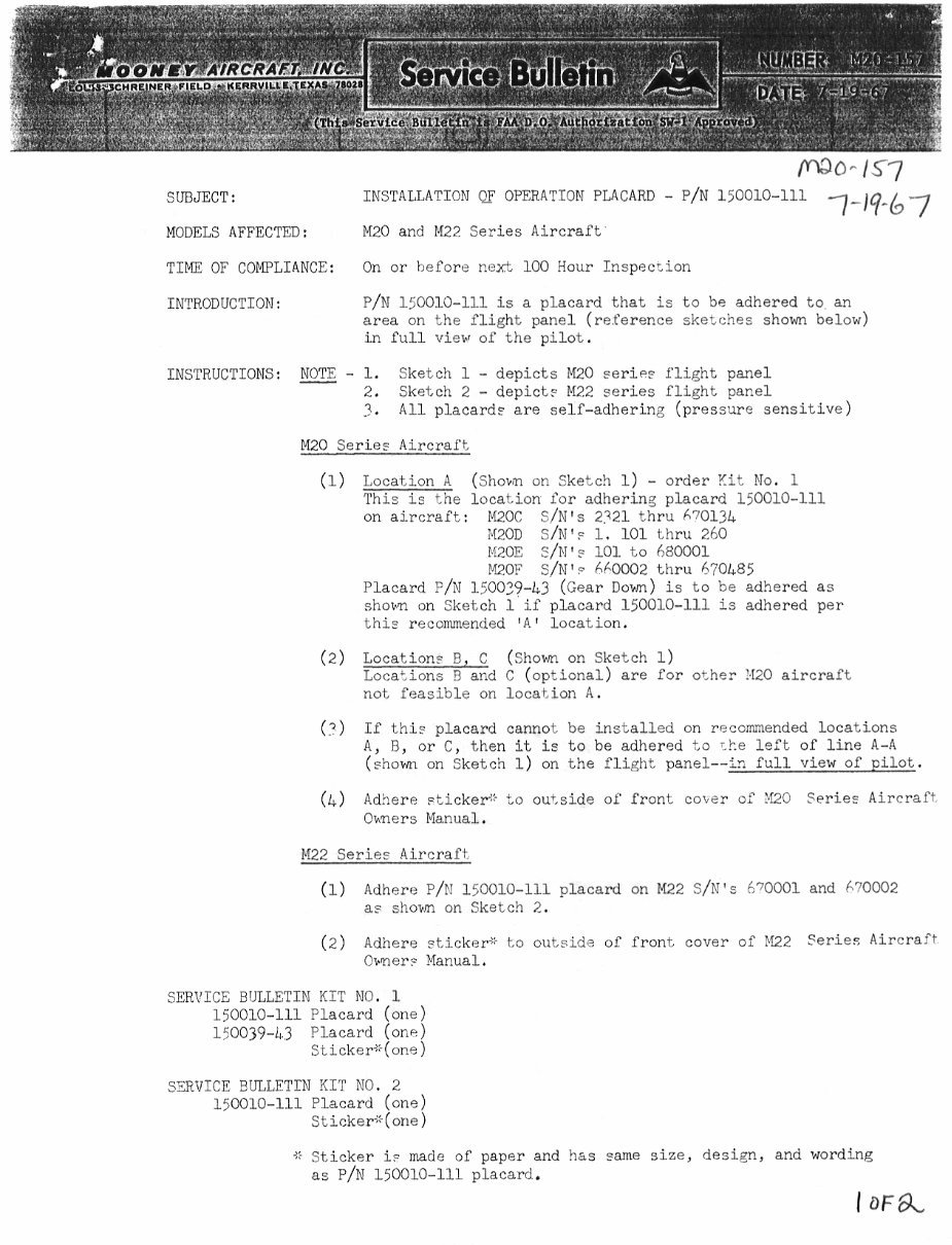
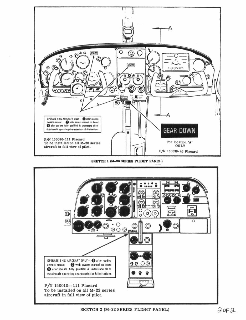
/nao-1~7 SVBJECT: INSTALLATION OF OPERATION PW\CARO P/N 150010-111 MODELS EFFECTED: M20 and IM22 Series Aircraft TIME OF COMPLIIINCE: On or before neX, 100 iiour Inspection INTRODIICTION: P/N 150010-111 is a placard that is to be adhered to an area on the flight panel (ret’erence shefches shown below) in full view of the pilot. INSTRL[CTIONS: NOTE -1. Sketch 1- depicts hlZO series flight panel 2. Sketch 2 depicts M22 series flight panel All placards are self-adhering (pressure sensitive) M20 Series Aircraft (1) Location A (Shounn on Sketch 1) order Kit No. 1 This is the location far adhering placard 150010-111 on aircraft: M20C S/Nls 2121 thru h?013L #200 S/N’E i. 101 thru 2hO EZ20E S/M’s 101 to h80001 E70F 9/N’´• hi´•0002 thru h70~85 Placard F/I 1:00:9-b3 (Gear Ooum) is to be adhered as sho~a on Sketch 1 if placard 150010-111 is adhered per this recommended 1A’ location. (2) YIILI-V´•II YI Y (Sho~ on Sketch 1) Locationl B C Locaiions B and C (optional) are for other ’120 aircraft not feasible on location A. If thi´• placard cannot be installed on recommended locations A, R, or C, then it is to be adhered to ;te left of line A-A (shorn~ on Sketch 1) an the flieht panel--;r full view of pilot. (L) AdilerP rticker’’ to outside of front coier of ?I?O Series Aircraft Oxners Manual. M22 Series iiircraSt (1) Adhere P/I 150010-111 placard on M22 S/hi’s C.70001 and ~70002 as shorn~ an Sketch 2. (2) Adhere sticker" to outside of front cover of ~22 Series Aircraf~ Ouiner; Manual. SERVICE BIILLETIN KIT NO. 1 150010-111 Placard lane) li0019-h3 Placard (or,p) Stic~eri’(ons SZRTIICE BlJLLFTIN KIT NO. 2 ,,,,,,.,,I it Sticker is made of paper and has same size, desian, and wording as P/N 150010-111 placard. I oFa
i ~k, o 09 a ‘B ´•I(´•01*1.): oh :-I onaet lilt Il´•Ulrl ONLI-O´•II´• I´•UI´•l M IN´• ~I´• II~ I´• U1 o hr~un *lh rlili´• L Ua~ III* Ihllil~lll´•l´•l´•li´•( Il´•l´•LI´•lllillb li´•il´•li´•l. PJN 150010-111 Plpep~ To be Lnsta~led an 1I1 M-20 esrisa ~ar locPLLon ’A’ drcralt in Lull vie. alpllot. ONI.Y P/N 150038-45 PLpeard BYLTCB 1 nm aERIE8 PLI(IIP~ PANEL) s BO o 6’ O Q 90~ Q oPrlnrs THS I1RCRl\lr ONLY- Oall,~ raaling awara manull 8 with awnsr manuai an bpard O 8 ear vau all st v a und,l.,nl all ol ´•00 P/N 150010--111 Placard To be installed on all M-22 series aircraft in full view of pilot. SKETCH 2 (M-22 SERIES FLIGRI~ PANEL) of a
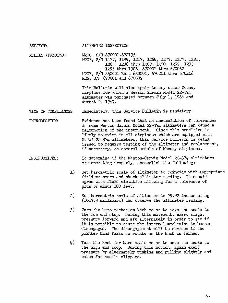
SUBJECT: ALTIMETER INSPECTION MODELSPI~EC1TED: ~zoc, S/N 670001-670135 ~20E, S/N 1177, 1199, 1217, 1268, 1273, 1277, 1281, 1283, 1286 thru 1288, 1290, 1292, 1293, 1295 thru 1308, 670001 thru 670062 ~20F, S/N 660001 ihru 660004, 670001 thru 670446 P122, S/N 670001 and 670002 This Bulletin will also apply to any other Mooney airpla3le for which a Trleston-Garwin Model 22-374 aftimeter was purchased between July i, 1966 and August 2, 1967. ~E OF COMPLIANCE: Immedia’;ely, this Service Bulletin is mandatory. INTRODUCTION= Evidence has been found that an accumulation of tolerances in some Weston-Garwin Model 22-374 altimeters can cause a malfunction of the instrument. Since this condition is li~ely to exist in all airplanes which are equipped with Model 22-374 altimeters, this Service Bulletin is being issued to require testing of the altimeter and replacement, if necessary, on several models of Mooney airplanes. II~STfLUCTIONS: To determine if the Weston-Gar~Jin Model 22-374 altimeters are operating properly, accomplish the following: 1) Set barometric scale or" altimeter to coincide with appropriate field. pressure and check altimeter reading. It should agree with field elevation allowing for a tolerance of plus or minus 100 feet. 2) Set barometric scale of altimeter to 29.92 inches of hg (1013.3 mi77;hars) and observe the altimeter reading. 3) Turn the bare mechanism so as to move the scale to the low end stop. During this movement, exert slight pressure forward and aft alternately in order to see if it is possible to cause the internal mechanism to become disen,oa,Ped. The disengagement will be obvious if the pointer hand fails to rotate as the knob is turned. 4) Turn the knob for bare scale so as to move the scale to the high end stop. During this motion, again exert pressure by alternately pushing and pulling slightly and watch for needle slippage.
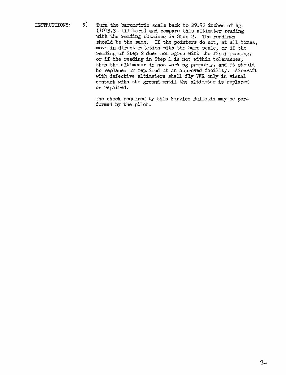
INSTRUCTIONS: 5) Turn the barometric scale back to 24.42 inches of hg (1013,3 and compare this altimet;er reading with the reading obtained in Step 2. The readings should be the same. If the pointers do not, at all times, move in direct relation with the bare scale, or if the reading of Step 2 does not agree with the final reading, or if the reading in Step 1 is not within tolerances, then the altimeter is not working properly, and ii; should be replaced or repaired at an approved facility. Aircraft with defective altimeters shall fly VFR only in visual contact with the ground until the altimeter is replaced or repaired. The check required by this Service Bulletin may be per- formed by the pilot. ~ZI´•
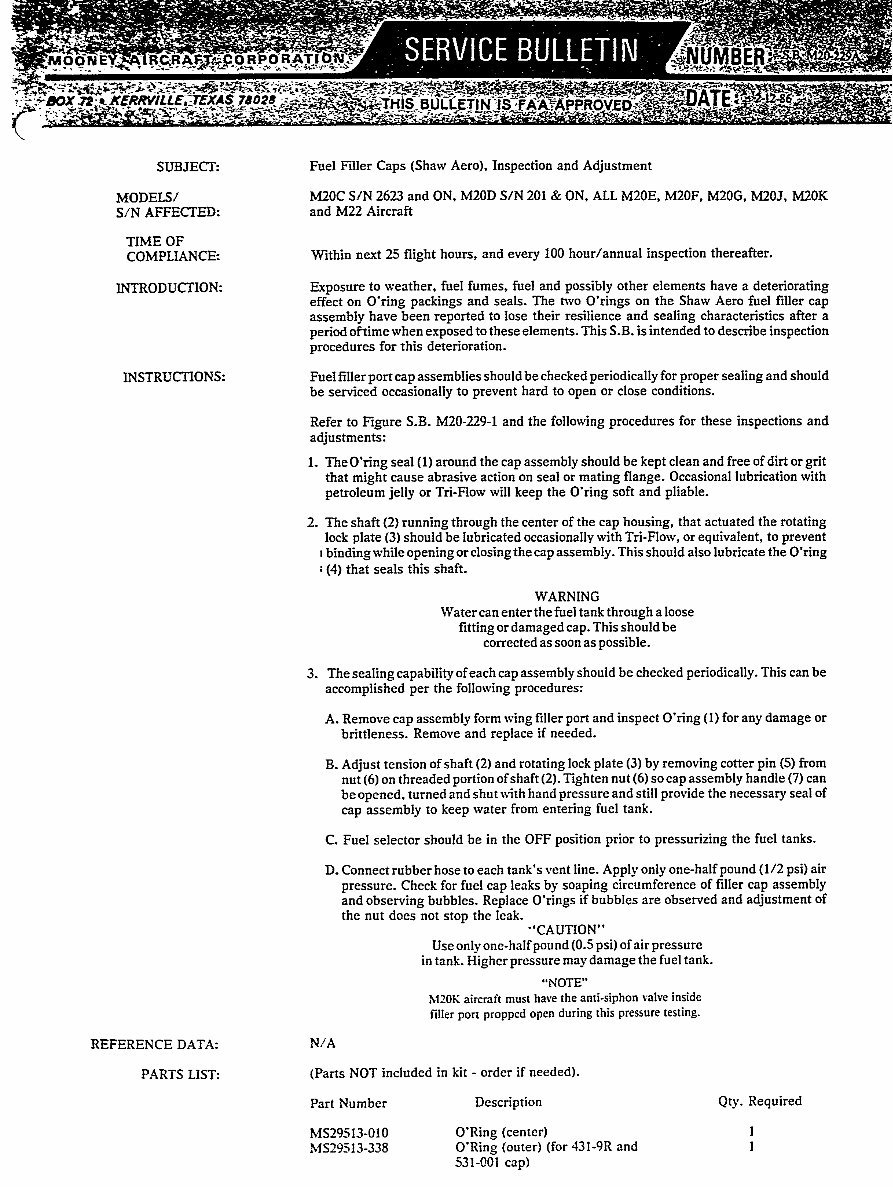
OON R~C;SA -9 i" dOX Zlrz 36 ´•1. SUB;IECT: Fuel Filler Caps (Shaw Aero), Inspection and Adjustment MODUS/ MZ0C S/N 2623 and ON, M20D S/N 201 gr ON, ALL M20E, M20F, M20G, M20J, M20K S/N AFFECTED: and M22 Aircraft TIME OF COMPLIANCE: Within next 25 night hours, and every 100 hour/annual inspection thereafter. INTRODUCTION: Exposure to weather. fuel fumes, fuel and possibly other elements have a deteriorating effect on O’ring packings and seals. The two O’rings on the Shaw Aero fuel filler cap assembly have been reported to lose their resilience and sealing characteristics after a period oftime when exposed to these elements. This S.B. is intended to describe inspection procedures for this deterioration. INSTRUCTIONS: Fuel filler port cap assemblies should be checked periodically for proper sealing and should be serviced occasionally to prevent hard to open or close conditions. I Refer to Figure S.B. M20-229-1 andthe following procedures for these inspections and adjustments: i. TheO’ring real (1) amur.d the cap assembb should be kept clean and free of dirt orgrit that might cause abrasive action on seal or mating nange. Occasional lubrication with petroleum jelly or Tri-Flow will keep the O’ring soft and pliable. 2. The shaft (2) running through the center of the cap housing, that actuated the rotating lock plate (3) should be lubricated occasionally with Tri-Flow, or equivalent, to prevent I binding while opening or closing the cap assembly. This should also lubricate the O’ring ;(4) that seals this shaft. WARNING Water can enter the fuel tank through a loose fitting or damaged cap. This should be corrected as soon as possible. 3. The sealing capability of each cap assembly should be checked periodically. This can be accomplished per the following procedures: A. Remove cap assembly form wing filler port and inspect O’ring (1) for any damage or brittleness. Remove and replace if needed. B. Adjust tension of shaft (2) and rotating lock plate (3) by removing cotter pin (5) from nut (6) on threaded portion of shaft t2). Tighten nut (6) so cap assembly handle (7) can be opened, turned and shut with hand pressure and still provide the necessary seal of cap assembly to keep water from entering fuel tank. C. Fuel selector should be in the OFF position prior to pressurizing the fuel tanks. D. Connect rubber hose to each tank’s vent line. Apply only one-half pound (1/2 psi) air pressure. Check for fuel cap leaks by soaping circumference of ftlIer cap assembly and observing bubbles. Replace O’rings if bubbles are observed and adjustment of the nut does not stop the leak. ’’CAUTION" Use only one-half pou nd (0.5 psi) of air pressure in tank. Higher pressure ma~ damage the fuel tank. "NOTE" MZOI< aircraft must have the anti-siphon valve inside filler port propped open during this pressure testing. REFERENCE DATA: N/A PARTS LIST: (Parts NOT included in kit order if needed). Part Number Description Qty. Required MS29513-010 O’Ring tcenter) 1 MS29513-338 O’Ring touter) (for 431-9R and 1 531-001 cap)
You're Reading a Preview
What's Included?
Lifetime Access
Fast Download Speeds
Offline Viewing
Access Contents & Bookmarks
Full Search Facility
Print one or all pages of your manual
$52.99$68.99
Mooney M20B Service Manual & Parts Catalog & Owner -3- Manuals -
These comprehensive technical manuals provide essential instructions for maintaining and servicing your equipment, complete with detailed diagrams and manufacturer specifications. They are invaluable resources for both professional mechanics and DIY enthusiasts.
The manuals offer simple navigation with convenient chapter bookmarks and the ability to search by keyword. You can easily print the entire manual or select specific sections for your work.
INSTANT - NO WAITING
LANGUAGE: English
FORMAT: PDF for Mooney M20B Service & Maintenance Manual, Illustrated Parts Catalog, and Owner's Manual; OVA for Mooney Service Publications
COMPATIBLE: Win/Mac
SEARCHABLE - BOOKMARKED - INDEXED
Each chapter is fully bookmarked for easy navigation, allowing you to quickly locate the exact service repair procedures. The manuals feature detailed illustrations, exploded diagrams, drawings, and photos to guide you through every service repair procedure.
Furthermore, they are completely indexed, bookmarked, and searchable, with numerous pictures, diagrams/illustrations, and charts. Whether it's for tune-ups, regular maintenance, or repairs, these manuals provide the technical details and step-by-step instructions you need.
The following Mooney M20B files are included:
Mooney M20B Service & Maintenance Manual
Mooney M20B Illustrated Parts Catalog
Mooney M20B Owner's Manual
Mooney Service Publications - Information, Bulletins & Ads
For immediate access to these manuals, simply click the green & white "NOW" button at the top right-hand side of this page. If you require any other manuals, feel free to email us, as we have thousands available.
Reviews
Q&A
Recently Viewed
5,521,897Happy Clients
2,594,462eManuals
1,120,453Trusted Sellers
15Years in Business
Price:
Actual Price:
Mooney M20B Service Manual & Parts Catalog & Owner -3- Manuals -



 Lifetime Access




