


ST
I
I
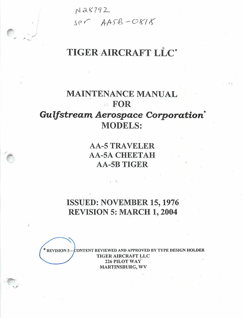
TIGER AIRCRAFT LLC
MAINTENANCE MANUAL
FOR
Gulfstream Aerospace Corporation*
MODELS:
AA-5 TRAVELER
AA-5A CHEETAH
AA-5B TIGER
ISSUED: NOVEMBER 15,1976
REVISION 5: MARCH 1, 2004
* REVISION 5 -CONTENT REVIEWED AND APPROVED BYTYPE DESIGN HOLDER
TIGER AIRCRAFT LLC
226 PILOT WAY
MARTINSBURG, WV
JfpN
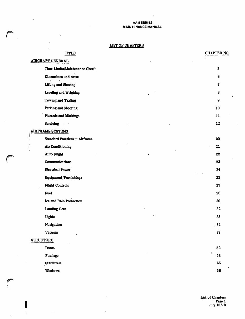
TITLE
AIRCRAFT GENERAL
Time Limits/Maintenance Check
Dimensions and Areas
Lifting and Shoring
Leveling and Weighing
Towing and Taxiing
Parking and Mooring
Placards and Markings
Servicing
AIRFRAME SYSTEMS
Standard Practices — Airframe
Air Conditioning
Auto Flight
Communications
Electrical Power
Equipment/Furnishings
Flight Controls
Fuel
Ice and Rain Protection
Landing Gear
Lights
Navigation
Vacuum
STRUCTURE
Doors
Fuselage
Stabilizers
Windows
A A-5 SERIES
MAINTENANCE MANUAL
LIST OF CHAPTERS
CHAPTER NO.
5
6
7
8
9
10
11
12
20
21
22
23
24
25
27
28
30
32
33
34
37
52
53
55
56
List of Chapters
Page 1
July 15/78

TITLE
Wings
PROPELLER
Propellers
POWER PLANT
Power Plant General
Engine Fuel and Control
Ignition
Engine Indicating
Exhaust
* 0iI
$ Starting
chajJts
Charts
A A-5 SERIES
MAINTENANCE MANUAL
UST OF CHAPTERS
CHAPTER NO.
57
61
71
73
74
77
78
79
80
91
List of Chapters
Page 2
July 15/78
AA-5 SERIES
MAINTENANCE MANUAL
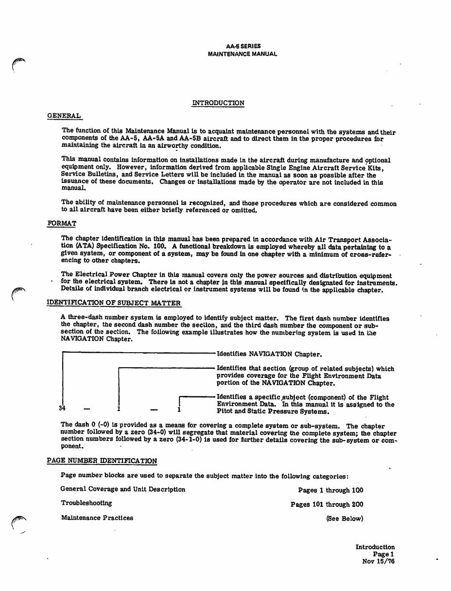
INTRODUCTION
GENERAL
The function of this Maintenance Manual Is to acquaint maintenance personnel with the systems andtheir
components of the AA-5, AA-5A and AA-5B aircraft and to direct them in the proper procedures for
maintaining the aircraft In an airworthy condition.
This manual contains Information on installations made in the aircraft during manufacture and optional
equipment only. However, informationderived from applicable Single EngineAircraft Service Kits,
Service Bulletins, and Service Letters will be included in the manual as soon as possible after the
issuance of these documents. Changes or installations made by the operator are not Included In this
manual.
The ability of maintenance personnel is recognized, andthose procedures which are considered common
to all aircraft have been either briefly referenced or omitted.
FORMAT
The chapter identification in this manual has been prepared In accordance withAir Transport Associa
tion (ATA) Specification No. 100. A functional breakdown is employed whereby all data pertaining to a
given system, or component of a system, may be found In one chapter with a minimum of cross-refer
encing to other chapters.
The Electrical Power Chapter in this manual covers only the power sources anddistributionequipment
- for the electrical system. There is not a chapter in this manual specifically designated for instruments.
Details of individual branch electrical or instrument systems will be found in the applicable chapter.
IDENTIFICATION OF SUBJECT MATTER
A three-dash number system is employed to Identify subject matter. The first dash number Identifies
the chapter, the second dash number the section, and the third dash number the component or sub
section of the section. The following example illustrates how the numbering system is used in the
NAVIGATION Chapter.
34 - l — i
•Identifies NAVIGATION Chapter.
• Identifies that section (group of related subjects) which
provides coverage for the Flight Environment Data
portion of the NAVIGATION Chapter.
•Identifies a specific subject (component) of the Flight
Environment Data. In this manual It is assigned to the
Pitot and Static Pressure Systems.
The dash 0 (-0) is provided as a means for covering a complete system or sub-system. The chapter
number followed by a zero (34-0) will segregate that material covering the complete system; the chapter
section numbers followed by a zero (34-1-0) is used for further details covering the sub-system or com
ponent.
PAGE NUMBER IDENTIFICATION
Page number blocks are used to separate the subject matter into the following categories:
General Coverage and Unit Description Pages 1 through 1Q0
Troubleshooting Pages 101 through 200
Maintenance Practices (See Below)
Introduction
Pagel
Nov 15/76
AA-5 SERIES
MAINTENANCE MANUAL
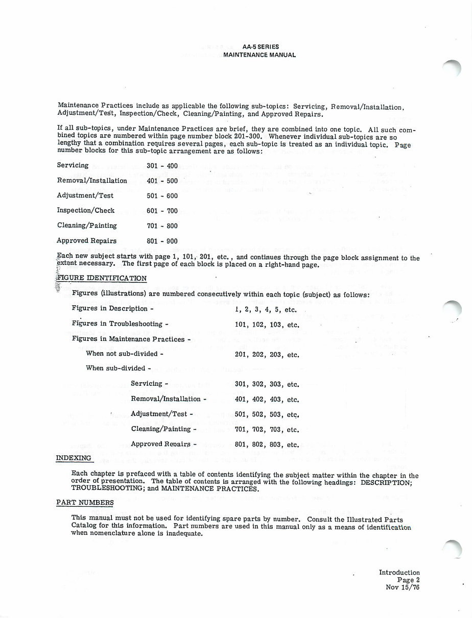
Maintenance Practices include as applicable the following sub-topics: Servicing, Removal/Installation.
Adjustment/Test, Inspection/Check, Cleaning/Painting, and Approved Repairs.
If all sub-topics, under Maintenance Practices are brief, they are combined into one topic. All such com
bined topics are numbered withinpage number block 201-300. Whenever individualsub-topics are so
lengthy thata combination requires several pages, each sub-topic is treated as an individual topic. Page
number blocks for this sub-topic arrangement are as follows:
Servicing 301 - 400
Removal/Installation 401 - 500
Adjustment/Test 501 - 600
Inspection/Check 601 - 700
Cleaning/Painting 701 - 800
Approved Repairs 801 - 900
Each new subjectstarts with page 1, 101, 201, etc., and continues through the page block assignment to the
extent necessary. The first page of each block is placed on a right-hand page.
I
-FIGURE IDENTIFICATION
Figures (illustrations) are numbered consecutively within each topic (subject) as follows:
Figures in Description - 1, 2, 3, 4, 5, etc.
Figures in Troubleshooting - 101, 102, 103, etc.
Figures in Maintenance Practices -
When not sub-divided - 201, 202, 203, etc.
When sub-divided -
Servicing- 301, 302, 303, etc.
Removal/Installation - 401, 402, 403, etc.
Adjustment/Test - 501, 502, 503, etc.
Cleaning/Painting- 701, 702, 703, etc.
Approved Reoairs - 801, 802, 803, etc.
INDEXING
Each chapter is prefaced with a table of contents identifying the subject matter within the chapter in the
order of presentation. The table of contents is arranged with the following headings: DESCRIPTION:
TROUBLESHOOTING; and MAINTENANCE PRACTICES.
PART NUMBERS
This manual must not be used for identifying spare parts by number. Consult the Illustrated Parts
Catalog for this information. Part numbers are used in this manual only as a means of identification
when nomenclature alone is inadequate.
Introduction
Page 2
Nov 15/76
J#*N
AA-5 SbRIES
MAINTENANCE MANUAL
REVISIONS
Revisions to the original text are indicated by vertical lines in the left margin of the page, adjacent to
the revised material.
The manual is provided with a "Record of Revisions" page for recording revisions by number and the
dates on which they were inserted in the manual.
Each page revised or added to the Initial manual will be identified by the date of revision at the bottom
of the page. Pages issued with the original manual are identified with the issue date of the manual.
Each revision also contains a "List of Effective Pages". This list contains the chapter, page number,
and date of each page which is effective since the issuance of the initial manual. This list Is updated
for each revision, with page changes indicated by the number of asterisks (*) placed adjacent to the
page number as noted below:
*Pages revised by the current revision.
♦♦Pages added by the current revision.
♦♦♦Pages deleted by the current revision.
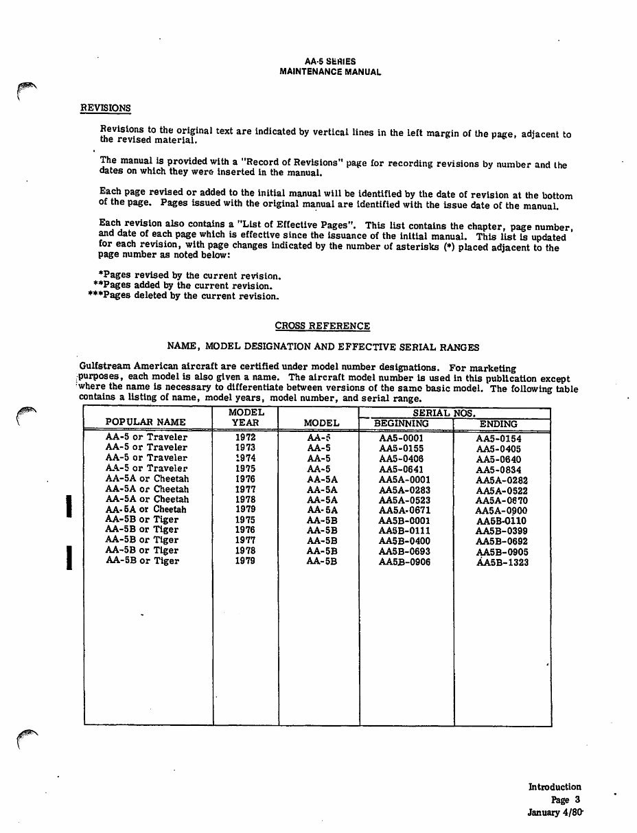
CROSS REFERENCE
NAME, MODEL DESIGNATION AND EFFECTIVE SERIAL RANGES
Gulfstream Americanaircraft are certified under model number designations. For marketing
.purposes, each model is also given a name. The aircraft modelnumber is used in this publication except
where the name is necessary to differentiate between versions of the same basic model. The following table
contains a listing of name, model years, model number, and serial range.
POPULAR NAME
MODEL
YEAR MODEL
SERIAL NOS.
BEGINNING ENDING
AA-5 or Traveler
AA-5 or Traveler
AA-5 or Traveler
AA-5 or Traveler
AA-5A or Cheetah
AA-5A or Cheetah
AA-5 A or Cheetah
AA- 5A or Cheetah
AA-5B or Tiger
AA-5B or Tiger
AA-5B or Tiger
AA-5B or Tiger
AA-5B or Tiger
1972
1973
1974
1975
1976
1977
1978
1979
1975
1976
1977
1978
1979
AA-5
AA-5
AA-5
AA-5
AA-5A
AA-5A
AA-5 A
AA-5A
AA-5B
AA-5B
AA-5B
AA-5B
AA-5B
AA5-0001
AA5-0155
AA5-0406
AA5-0641
AA5A-0001
AA5A-0283
AA5A-0523
AA5A-0671
AA5B-0001
AA5B-0111
AA5B-0400
AA5B-0693
AA5B-0906
AA5-0154
AA5-0405
AA5-0640
AA5-0834
AA5A-0282
AA5A-0522
AA5A-0670
AA5A-0900
AA5B-0110
AA5B-0399
AA5B-0692
AA5B-0905
AA5B-1323
Introduction
Page 3
January 4/80"
/I^v
jSPfev
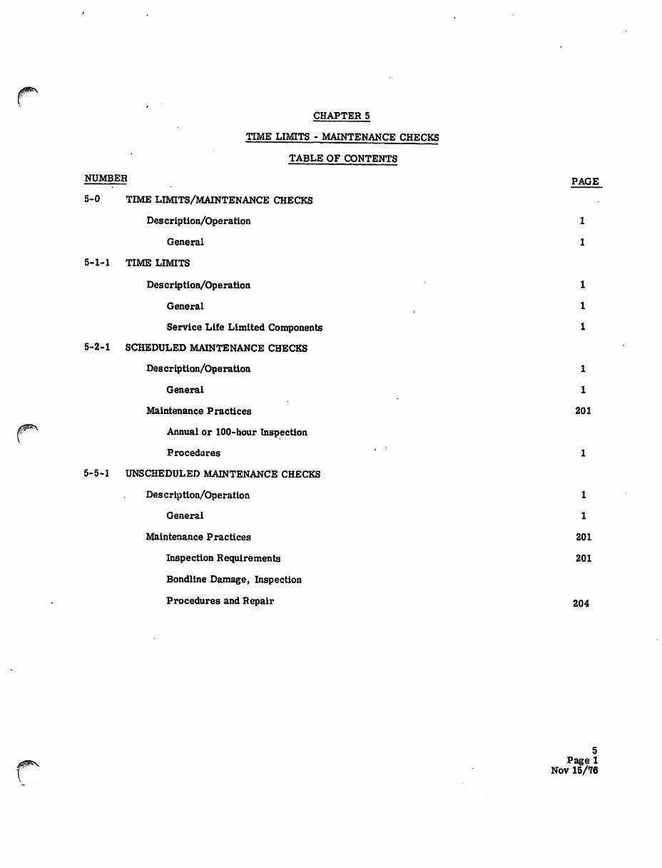
CHAPTER 5
TIME LIMITS - MAINTENANCE CHECKS
TABLE OF CONTENTS
NUMBER
5-0
TIME LIMITS/MAINTENANCE CHECKS
Descriptlon/Operatlon
General
5-1-1 TIME LIMITS
Description/Operation
General
Service Life Limited Components
5-2-1 SCHEDULED MAINTENANCE CHECKS
Description/Operation
General
Maintenance Practices
Annual or 100-hour Inspection
Procedures
5-5-1 UNSCHEDULED MAINTENANCE CHECKS
Description/Operation
General
Maintenance Practices
Inspection Requirements
Bondline Damage, Inspection
Procedures and Repair
PAGE
1
1
1
1
1
1
1
201
1
1
201
201
204
5
Page 1
Nov 15/76
JPN
AA-5 SERIES
MAINTENANCE MANUAL
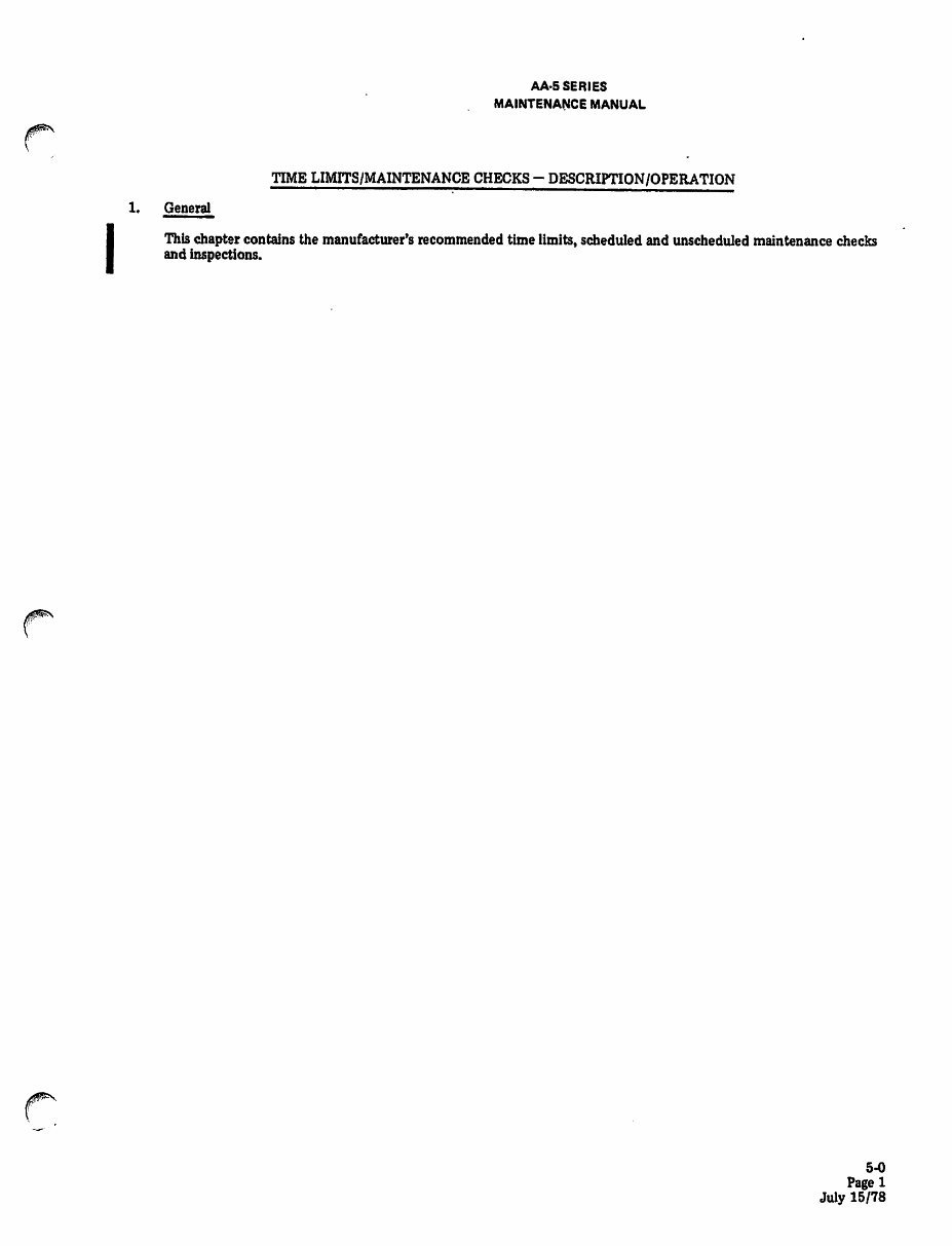
TIME LIMITS/MAINTENANCE CHECKS- DESCRIPTION/OPERATION
1. General
This chapter contains the manufacturer's recommended time limits, scheduled and unscheduled maintenance checks
and inspections.
5-0
1
July 15/78
• /S0&\
AA-5 SERIES
MAINTENANCE MANUAL
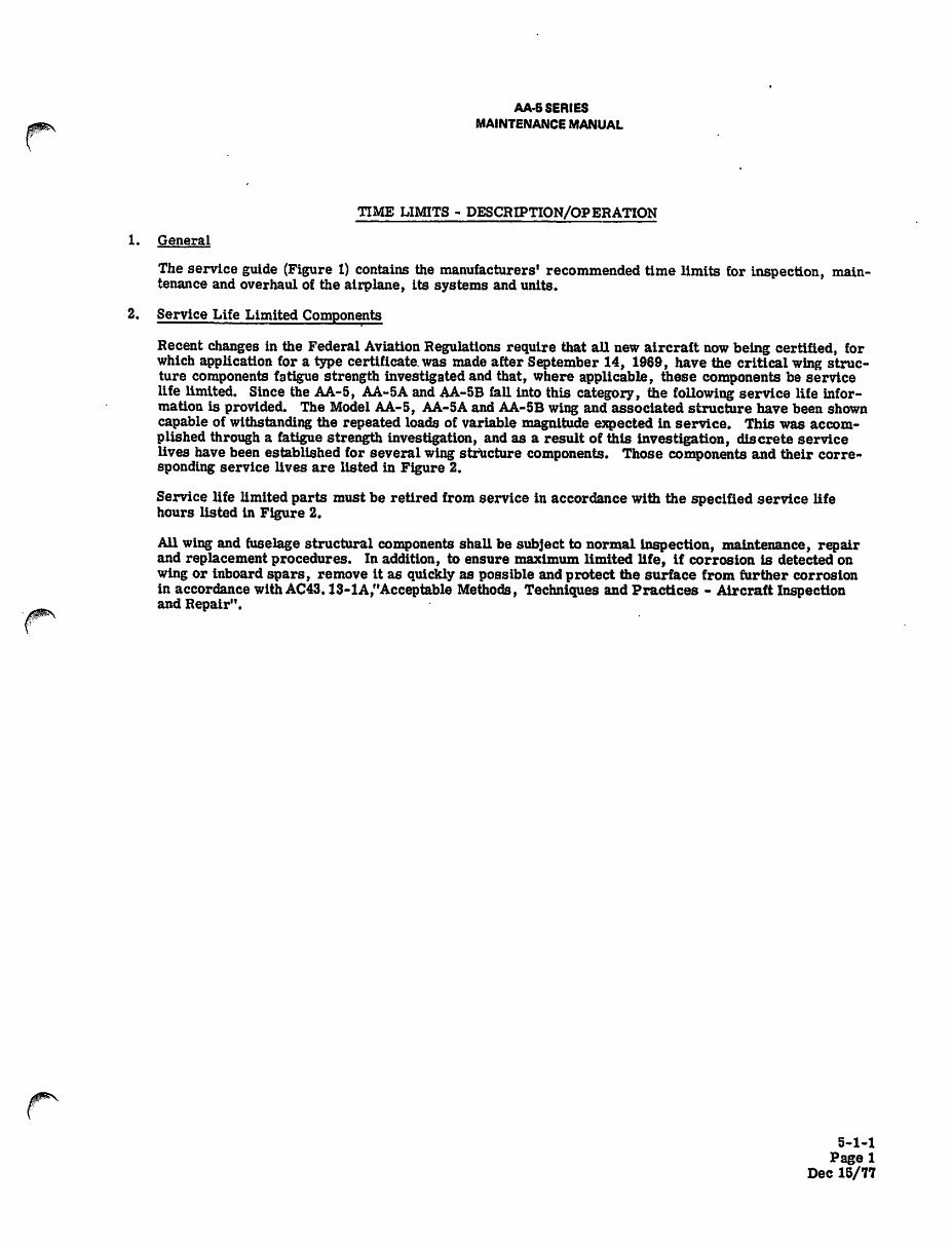
TIME LIMITS - DESCRIPTION/OPERATION
1. General
The service guide (Figure 1) contains the manufacturers' recommendedtime limits for inspection, main
tenance and overhaul of the airplane, its systems and units.
2. Service Life Limited Components
Recent changes in the Federal Aviation Regulations require that all new aircraft nowbeing certified, for
which application for a type certificate,was made after September 14, 1969, have the critical wing struc
ture components fatigue strength Investigated and that, where applicable, these components be service
life limited. Since the AA-5, AA-5A and AA-5B fall into this category, the following service life infor
mation is provided. The Model AA-5, AA-5A and AA-5B wing and associated structure have been shown
capable of withstanding the repeated loads of variable magnitude expected in service. This was accom
plished through a fatigue strength investigation, and as a result of this Investigation, discrete service
lives have been established for several wing structure components. Those components and their corre
sponding service lives are listed in Figure 2.
Service life limited parts must be retired from service in accordance with the specified service life
hours listed in Figure 2.
All wing and fuselage structural components shall be subject to normal inspection, maintenance, repair
and replacement procedures. In addition, to ensure maximum limited life, If corrosion is detected on
wing or inboard spars, remove it as quickly as possible and protect the surface from further corrosion
in accordance with AC43.13-1A,"Acceptable Methods, Techniques and Practices - Aircraft Inspection
and Repair".
5-1-1
Pagel
Dec 15/77
AA-5 SERIES
MAINTENANCE MANUAL
SCHEDULED MAINTENANCE CHECKS - DESCRIPTION/OPERATION
1. General
The inspection procedures guideline included in this section may be used by the owner, inspector, or
mechanic to ensure complete and comprehensive coverage of the inspection requirements. The format
of the procedures canbe reproduced for ready use by the personnel performing the inspection. The
checklist includes the minimum requirements for the 100-hour or annual inspection.
5-2-1
Pagel
Nov 15/76
You're Reading a Preview
What's Included?
 Lifetime Access
Fast Download Speeds
Online & Offline Access
Access PDF Contents & Bookmarks
Full Search Facility
Print one or all pages of your manual
$46.99
Grumman AA5 Traveler Cheetah Tiger Maintenance Manual
Viewed 75 Times Today

What's Included?
Lifetime Access
Fast Download Speeds
Online & Offline Access
Access PDF Contents & Bookmarks
Full Search Facility
Print one or all pages of your manual
$46.99

Secure transaction
What's Included?
Lifetime Access
Fast Download Speeds
Online & Offline Access
Access PDF Contents & Bookmarks
Full Search Facility
Print one or all pages of your manual
Description
The Grumman Aircraft AA5 Traveler Cheetah Tiger Maintenance Manual is a comprehensive guide spanning 773 pages, covering all years through 1979. This manual is available in a file format that is compatible with all versions of Windows, Mac, and Linux operating systems. It is designed to be easily printable and offers instant high-speed access. The only requirement for accessing this manual is having Adobe software installed.


