

CESSNA Citation II C551 SP2 OPERATING Manual
What's Included?
Fast Download Speeds
Online & Offline Access
Access PDF Contents & Bookmarks
Full Search Facility
Print one or all pages of your manual
Eaglesoft Development Group: Citation II SP/2 C551 Operating Manual
1
Cessna/Citation II
C551 SP/2
Operating Manual
by
Eaglesoft Development Group
Bill Leaming & Bob Hayes
Ron Hamilton, President
Eaglesoft Development Group: Citation II SP/2 C551 Operating Manual
2
Introduction
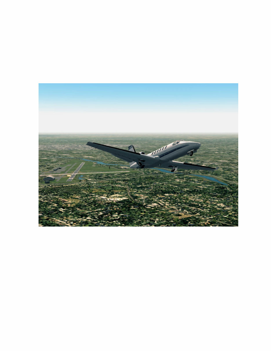
Thank you for your purchase of the Eaglesoft Citation II SP/2. We hope you enjoy flying her as much as we
have enjoyed building this aircraft. The Citation II SP/2 is also known as the Model C-551, which is a single-
pilot certified, twin engine business jet. Our model represents a recently refurbished, 1985 aircraft, which has
already provided a long service life.
This “Introduction” chapter will introduce the 2d panel, mousepoints, and discuss briefly the major instruments.
Detailed information on instrumentation will be covered in Chapter Two: Operating Manual, and Chapter
Three: EHSI. Chapter Four will cover Specifications, Operating Limitations, and Weight & Balance.
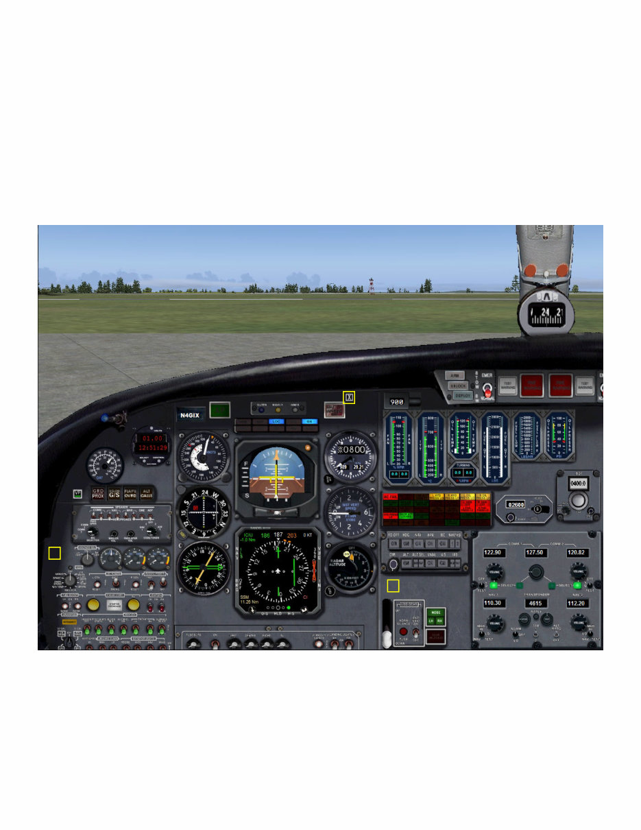
Main Panel:
This is a view of the main 2d panel, after the Master Battery and Avionics have been turned on. There are three
“hotspots” on the 2d panel, described as follows:
1) Toggles on/off a zoomed view of the Engine/Electrical subpanels.
2) Toggles on/off a view of the Course and Heading subpanel, which is normally found on the center throttle
console.
3) Toggles on/off the Simicons, which themselves will open/close various subpanels and popups.
1
2
3
Eaglesoft Development Group: Citation II SP/2 C551 Operating Manual
3
Introduction
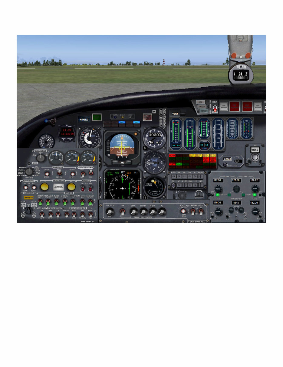
Main Panel:
In the picture above, all three of the “hotspots” have been activated, so you can see the zoomed view of the
Engine/Electrical subpanel, the AP/YD Master + Pitch + Rudder (Yaw) electrical trim controls, and finally, the
Simicons subpanel.
Please take note that every switch, knob and button on this panel features “custom tooltips,” which will clearly
identify the control by name, and in the case of many, will provide a “digital readout” of the value (such as Air-
speed, Airspeed Bug, Altimeter Kohlsman setting [both inHg and MB], Heading, Course, etc.), so even though
the text on the panel is small, there is no reason for despair! It was decided that our dedication to producing an
authentic, true-to-scale representation of the actual aircraft’s panel was something we weren’t willing to aban-
don, so I’ve taken great pains to make sure that every control is easily identifiable. Once you’ve become accus-
tomed to the panel, you might wish to switch off the “custom tooltips” via the FS Options menu. It is your
choice!
Eaglesoft Development Group: Citation II SP/2 C551 Operating Manual
4
Introduction
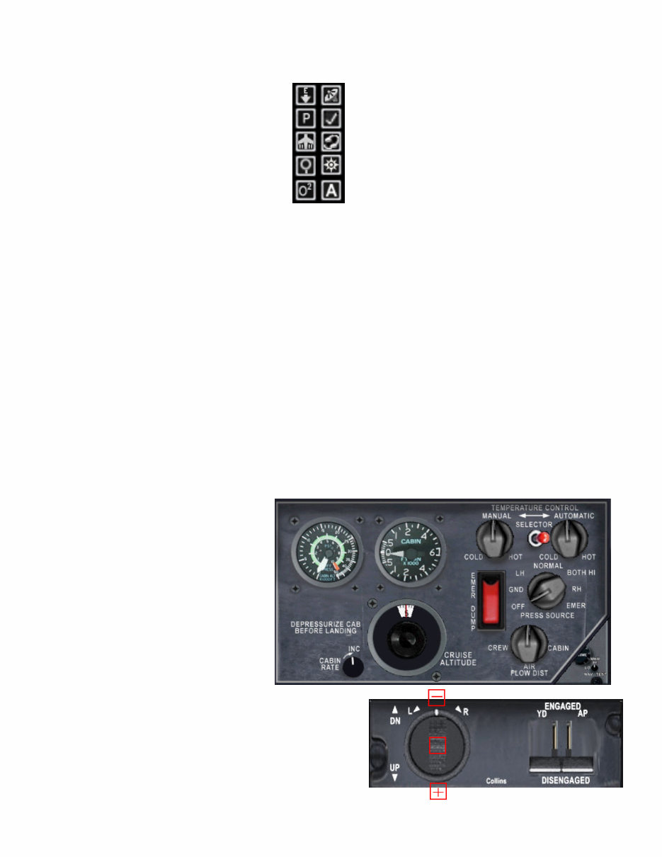
Main Panel:
Display/Hide Engine/Electrical subpanel
Display/Hide Pressurization subpanel
Display/Hide Throttle Quadrant
Display/Hide ADI & EHSI “Zoomed View”
Display/Hide GPS*
Display/Hide Engine/Electrical subpanel
Display/Hide Kneeboard/Checklist*
Display/Hide ATC Menu*
Display/Hide Map*
Display/Hide Audio Controls subpanel
NOTE: Asterisked Items are MSFS defaults
Getting Started Quickly:
The following procedure is not an official checklist, but rather is written so that the interminably anxious can
get the aircraft model started quickly and simply for their initial “test flight!” :)
1) Click on the X to open the Simicons subpanel, and click on the E-Arrow button to open the Eng/Elec panel.
2) Click on the “Airplane” button to open the Throttle Quad subpanel.
3) Turn on Master Battery and Avionics switches.
4) Make sure the Parking Brake is set (Ctrl-period).
5) Turn on the Right Ignition switch, and then click on the Right Engine Start (round yellow button).
6) As the engine spools up, click TWICE just below the Right Power Lever to switch ON the fuel valves. The
knob will move UP to the Idle detent. (Note: if you have a CH Yoke or other “mixture control”, make
sure it is fully forward!)
7) After the Right engine is started, switch OFF the R Ignition switch, and turn ON the L Ignition switch.
8) Press the yellow L engine Starter button, and click TWICE just below the Left Power Lever to open fuel
flow, just as you did before.
9) Switch OFF the L Ignition switch, and turn ON L & R Alternators and the Inverter Switch.
10) Close the Eng/Elec & Throttle Quad subpanels, by click on the appropriate Simicons, and Open the Pressur-
ization subpanel.
11) Use the “Cruise Altitude” knob to pre-
set your planned cruise altitude on the dial.
12) Set “Pressure Source” knob to
“Normal.” This will turn on the bleed air
needed by both the pressurization system
to work, and the air conditioning system.
(Note: except for the “Cabin Rate” and
“Emer Dump” switch, the remainder of
the knobs will simply “click, turn and
make noise...”)
13) Using the AP/Trim popup, pre-set elevator trim to 5.5º
positive trim, using either the +/- clickspots, or the mouse-
wheel. A “tooltip box” will provide a digital readout of the
trim setting.
M
Eaglesoft Development Group: Citation II SP/2 C551 Operating Manual
5
Getting Started Quickly:
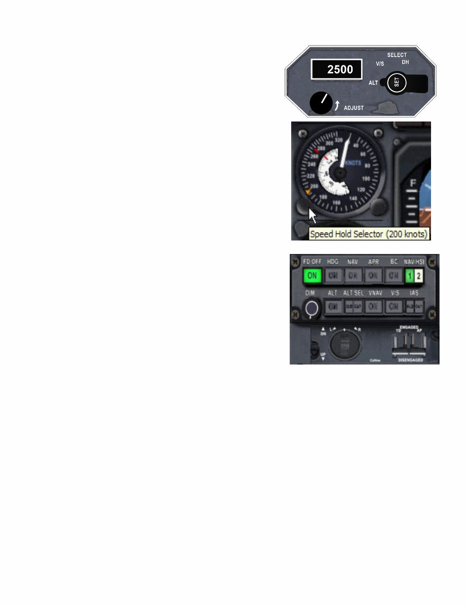
14) Preset your initial altitude using the AP Control panel, using
the “Adjust” knob. The V/S is pre-set by the .air file to 1800 fpm,
but you may adjust it manually by setting the “Select” knob to V/S
and using the “Adjust” knob. The DH (Decision Height) is likewise
pre-set to 300’ AGL, but may be changed at any time either here, or
using the knob on the Radar Altimeter.
15) Preset your initial Airspeed by using the left adjustment knob on
the Airspeed indicator. As you can see by the picture to the right, a
“custom tooltip” will display a digital reading of the bug’s position.
Note also the “red line” on the outer dial. This is the Vmo (never
exceed speed) limit of 262 KIAS for the aircraft below FL140.
The “red line” on the Mach Index (white scale) is the Vmo in mach,
which is .705 @ FL280 and above. The Mach Index may be ad-
justed using the right knob.
16) Turn ON the Flight Director by pressing the button conveniently
labeled “FD OFF” on the AP Mode Select subpanel.
Take note at this time of the other controls, especially the ALT and
IAS buttons. When you wish to turn control over to the autopilot,
click the AP lever to the UP position, then click on the ALT button.
Take care to notice that the IAS button is split: the left half is for “IAS
HOLD,” and the right half is for “IAS Capture.” The latter is a handy
feature when you simply want to “hold your current speed” without
having to fiddle with the Airspeed Bug on the Airspeed indicator! :)
The other buttons on the AP Mode Select panel work exactly the same as in any of the default FS autopilots,
except the NAV/HSI, ALT SEL, VNAV, and V/S modes which are not modeled by FS, so are inoperative in
this aircraft.
To quickly clear all modes on the AP Mode Select panel, turn OFF the FD mode.
17) After obtaining clearance, taxi out to the active and hold short, using small amounts of power. Make sure
that you don’t exceed any N1, ITT, or N2 limits while doing so.
18) While waiting for takeoff clearance, set flaps to 15º minimum! If you fail to set the flaps, you will hear a
very nasty, loud siren! (Note: should you set off the siren, clicking on the Master Warn light will silence the
siren for the current fault condition, but it will be reset for any further fault conditions).
Review your takeoff configuration to be absolutely positive that you have flaps 15º, 5º to 7.5º positive trim,
and the parking brake is released, prior to taxiing onto the active for takeoff.
18) Smoothly apply power and begin your takeoff roll, making sure to not exceed either 104% N1, or
96%N2. At 100 KIAS, the VF will call out “V1,” and at 110 KIAS the VF will call out “Rotate!” Immediately
raise the gear, and at around 500’ AGL, clean up the flaps. Congratulations! You are airborne! :)
Eaglesoft Development Group: Citation II SP/2 C551 Operating Manual
6
Operating Manual
General:
There are seven flight instruments that are common to both the pilot and (optional) co-pilot. They are operated
by a combination of pitot-static pressures, vacuum and AC/DC electrical power.
Primary Flight Instruments
Altimeters
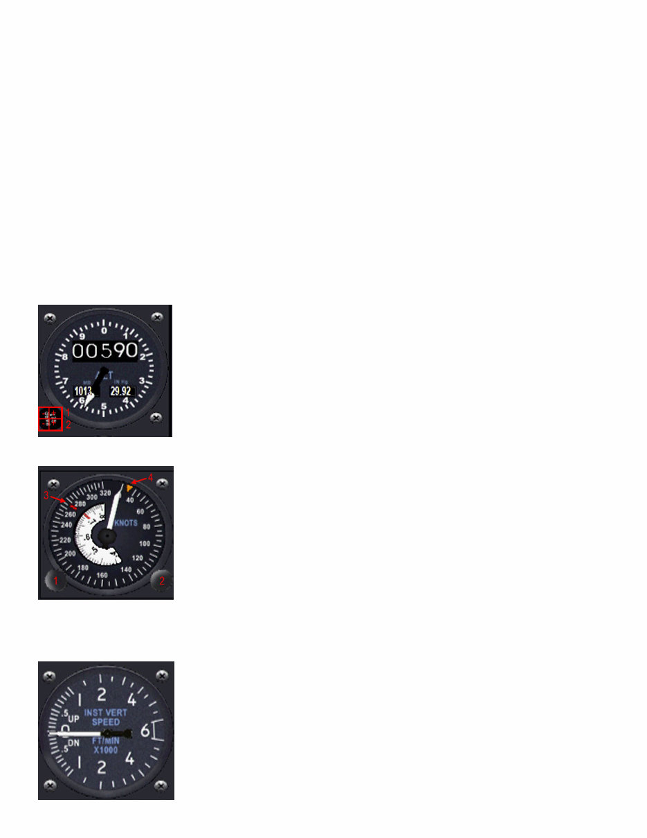
The altimeter provides a servoed drum/pointer display of barometrically corrected pressure altitude. AC power
from the Avionics bus is required for operation of the altimeter. The barometric pressure is set manually with
the BARO knob and is displayed in inches of mercury and millibars on the baro counters. The altimeter is
driven from an air data computer that provides sensors and electronic output for altitude. Both pilot and co-pi-
lot altimeters are identical.
1) Clicking on the top half of the baro knob will increase/decrease the pressure set-
ting. Mouse tooltips will display the pressure in inHg.
2) Clicking on the lower half of the baro knob will increase/decrease the pressure
setting. Mouse tooltips will display the pressure in millibars.
Airspeed
The airspeed indicators are identical and operate off uncorrected pitot- static input.
The instruments incorporate a single rotating needle, a fixed scale calibrated in
knots and a rotating mach scale. Slots in the airspeed dial at 262 and 277 KIAS
will show red below 14,000 feet and from 14,000-28,000 feet respectively, indicat-
ing Vmo limits. The mach limit of .705 above 28,000 feet is indicated by a single
red line. A knob on the lower right corner controls a moveable index that can be
set for reference.
1) Heading Bug Adjust 3) Vmo Limit Line(s)
2) Mach Index Adjust 4) Heading Bug
Vertical Speed Indicators
The two instantaneous vertical speed indicators indicate vertical velocity from 0 to
6,000 feet per minute, either up or down. Their operations differs from conven-
tional VSI’s in that there is nearly zero time lag between aircraft displacement and
instrument indication. Accelerometers sense any change in normal acceleration and
displace the needle before an actual pressure change occurs.
Eaglesoft Development Group: Citation II SP/2 C551 Operating Manual
7
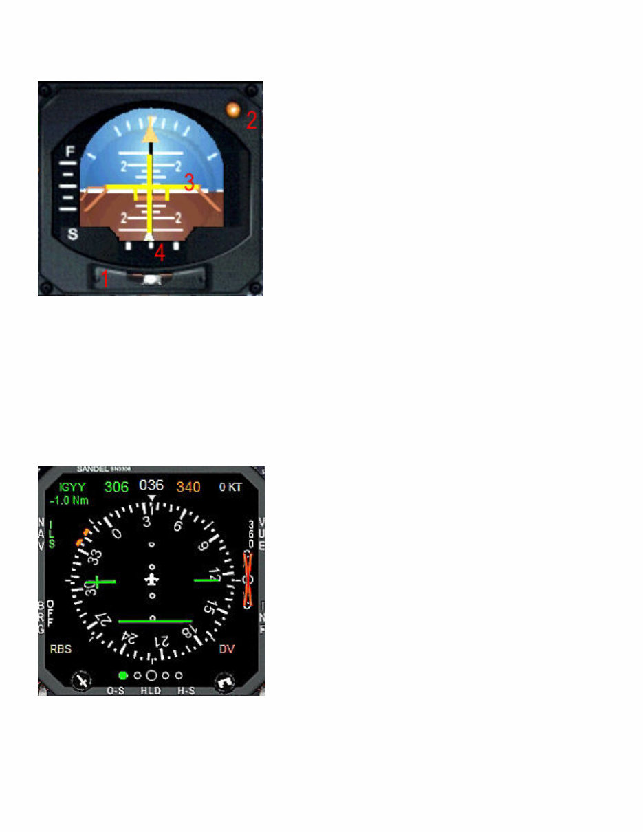
Attitude Director Indicator
The ADI displays aircraft attitude, computed roll and pitch steer-
ing commands and ILS raw data through the expanded localizer
needle. Pitch attitude is marked in five degree increments to 20º
of pitch, with additional marks at 30º, 40º and 90º. A fixed refer-
ence airplane displays actual aircraft position relative to the pitch
and roll attitudes of the ADI sphere. Also incorporated is an in-
clinometer indicating skid or slip conditions (1).
The flight director command bars are visible at all times, but are
not active until the flight director system is in operation. They
are positioned by the FD computer to display pitch and roll steer-
ing commands for the mode selected on the AP mode control
panel. Positioning the fixed reference aircraft to align it with the
command bars will give computed steering to intercept and track
a radial, glideslope, or whatever mode may be selected.
1) Inclinometer
2) Decision Height Indicator - This illuminates whenever the selected Decision Height is acquired.
3) Flight Director Command Bars
4) Localizer Needle
Electronic Horizontal Situation Indicator
The EHSI is a representation of the Sandel 3308 instrument.
This is a very complex instrument and will be covered in detail
in its own chapter of this Operations Handbook.
The Horizontal Situation Display shows heading and navigation
information in a 360º view similar to a conventional mechanical
HSI, or in an EFIS 120º ARC view. This includes compass card,
heading bug, course pointer, course deviation bar, TO/FROM
indicator, glideslope indicator and flags. Heading bug and
course pointer settings include digital, color coded readouts that
make it easy to set precise headings and courses. One button
operation allows primary navigation to be switched quickly be-
tween NAV1 and GPS sources, as well as the display of NAV2
and ADF receiver data. The entire display is color coded to
clearly indicate which navigation source is selected: green for
NAV2, yellow for NAV2, and cyan for GPS.
Since the 3308 is capable of displaying a huge amount of information simultaneously, there is a “de-clutter”
function that will allow you to display as much, or as little information as you desire with the touch of a single
button. You decide how much information to display, and when to display it.
Eaglesoft Development Group: Citation II SP/2 C551 Operating Manual
8
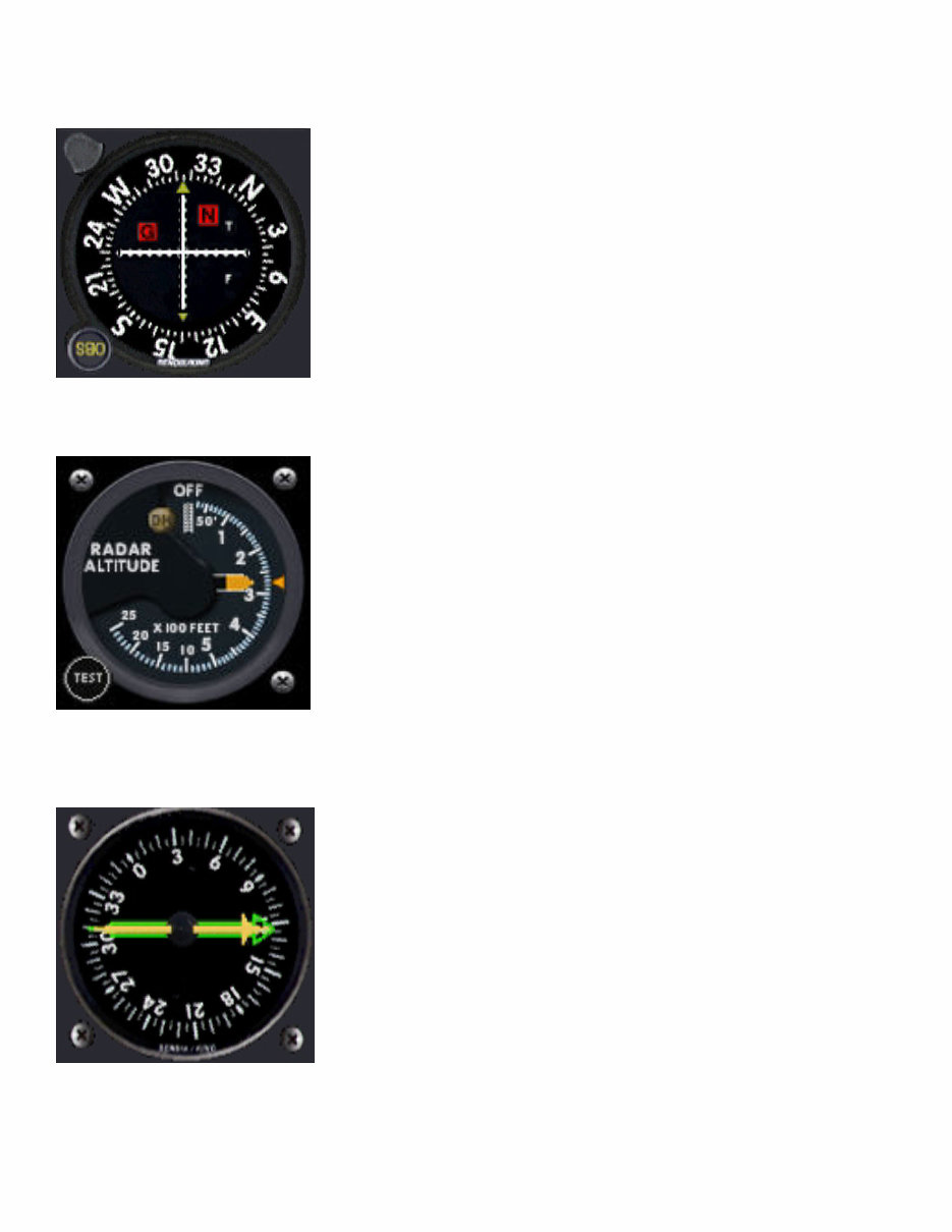
Bendix/King VOR2 Display
There are two standard Bendix/King VOR Displays installed on the air-
craft, which are driven by the NAV2 radio. They feature localizer and
glideslope deviation needles, TO/FROM, ILS and GS Inop flags. An OBS
(Omni Bearing Selector) knob is used to determine the desired heading
when tracking a radial from a VOR either inbound or outbound.
Radar Altimeter
A Radar Altimeter is installed on the pilot’s side of the panel only. The
Decision Height may be selected either with the knob on the instrument
display, or by the remote panel just above the radio stack. When the se-
lected DH is reached, a light on the Radar Altimeter will illuminate, and
the signal is repeated electrically to the display on the ADI.
RMI
A dual needle RMI is installed on the pilot’s side of the main panel. The
two needles are color coded: green for the ADF direction and yellow for the
VOR2 bearing. They are driven by the ADF receiver mounted just above
the main radio panel, and to the right of the Altitude/VS/DH remote selector
unit. These are used mainly for backup instrumentation and cross-checking
against the primary displays on the Sandel 3308 and VOR2 displays.
Eaglesoft Development Group: Citation II SP/2 C551 Operating Manual
9
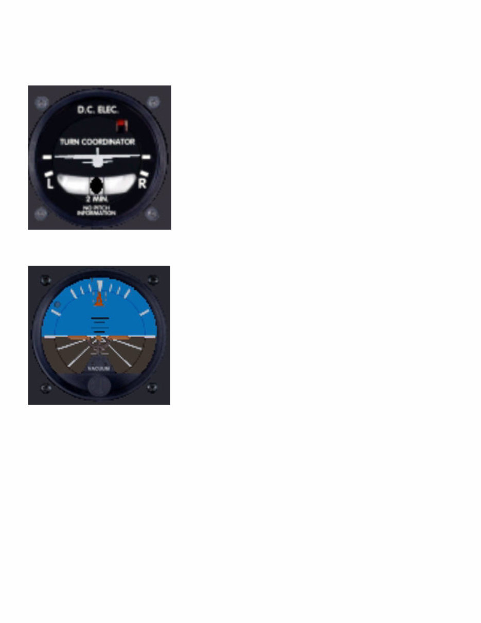
Backup Instruments
Turn and Bank Indicator
The co-pilot’s backup Turn and Bank Indicator is powered by 28 VDC
from the RH Crossover Bus through a circuit breaker on the left hand
circuit breaker panel. On OFF flag will come into view any time power
is interrupted.
Backup Artificial Horizon
The backup artificial horizon is located on the co-pilot’s side of the
main panel, just above the Garmin 500 GPS display. It is driven by a
separate attitude gyro which is driven by bleed air from either engine.
The attitude gyro will be operating anytime at least one engine is run-
ning. Due to the simplicity and reliability of the system, no warning
flags are provided. System pressure may be monitored through the
pressure indicator installed on the lower right side of the instrument
panel.
Eaglesoft Development Group: Citation II SP/2 C551 Operating Manual
10
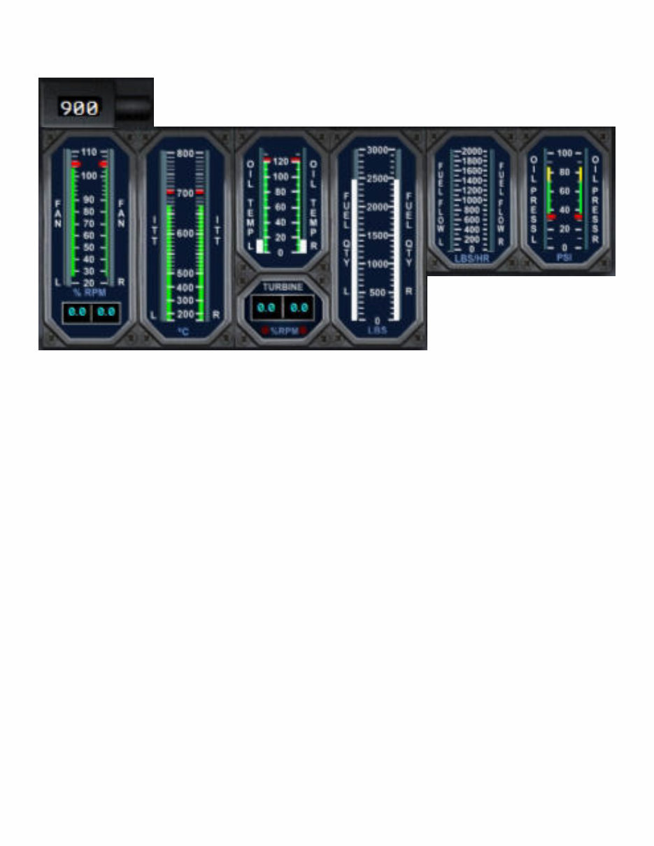
Engine Operations Display
All of the engine instruments are mounted in the center of the main panel, just under the glareshield annunciator
panel. Although all of the instruments are driven from the 28 VDC bus, in the event of total electrical failure,
the N1 tape indicator will continue to indicate accurately above 50% RPM as enough electrical current is gener-
ated by the tachometer generator to drive the tape servo. However, the N1 and N2 LED displays will extin-
guish. The Fan (N1) tachometer is located at the 12 o’clock position on the engine case and is driven by the
inner shaft from the low speed turbines. The Turbine (N2) tachometer is attached to the accessory case and is
driven by the accessory case gear box. The Inter-turbine temperature (ITT) is a computed temperature deter-
mined by multiplying the temperature rise of the air across the bypass duct by a factor of three and adding it to
the exhaust temperatures. This signal then goes to an amplifier and to a servo motor to position the tapes. The
tapes are calibrated from 100º C to 800º C with 700º C being the maximum allowable during any operation.
The fuel flow indicator receives its signal from the fuel flow transmitter down stream of the fuel control valves
and is calibrated from 100 to 2000 PSI.
1) N1 Dial - this is used simply to remind the pilot of the maximum N1 for takeoff and climbout operations.
2) N1 Engine Fan RPM: Redline at 104% RPM, normal range is 25% to 104% RPM
3) ITT: Redline at 700º C, Caution at 680º C to 700º C, normal range is 200º C to 680º C
4) Oil Temperature: Redline at 121º C, normal range is 0º C to 121º C
5) N2 Engine Turbine RPM: Red LEDs, flashing display and audible alert at 96% RPM
6) Fuel Quantity: self-explanatory, calibrated in LBS
7) Fuel Flow: self-explanatory, calibrated in LBS/Hour
8) Oil Pressure: Caution at 70 to 85 psi, normal range 35 to 70 psi, low caution at 35 psi
1
2 3
4
5 6
7 8
You're Reading a Preview
What's Included?
Fast Download Speeds
Online & Offline Access
Access PDF Contents & Bookmarks
Full Search Facility
Print one or all pages of your manual
$31.99
Viewed 85 Times Today


Secure transaction
What's Included?
Fast Download Speeds
Online & Offline Access
Access PDF Contents & Bookmarks
Full Search Facility
Print one or all pages of your manual
$31.99
The CESSNA Citation II C551 SP2 Operating Manual is an essential resource for anyone involved in the maintenance and repair of this aircraft model. Whether you are a professional mechanic or a DIY enthusiast, this manual provides detailed technical information to assist you in servicing the C551 SP2 effectively.
With comprehensive instructions and diagrams, this manual covers a wide range of topics including engine systems, electrical systems, fuel systems, and more. It is an invaluable tool for ensuring the proper functioning and safety of the C551 SP2.
Whether you are performing routine maintenance or troubleshooting a complex issue, this manual equips you with the knowledge needed to carry out tasks with confidence and precision.


