

Cessna Avionics manual D4606-13 service n parts manual
What's Included?
Fast Download Speeds
Online & Offline Access
Access PDF Contents & Bookmarks
Full Search Facility
Print one or all pages of your manual
REISSUE
MODELS 182, R182, 185,
U206, 207, AND 210 SERIES
1983 THRU 1985
AVIONIC INSTALLATIONS
SERVICE/PARTS MANUAL
20 JULY 1984
D4606-13
THE FOLLOWING AVIONICS INSTALLATIONS
SERVICE/PARTS MANUAL SUPERSEDES AND
REPLACES ALL D4604-13 AVIONIC INSTALLATIONS
SERVICE/PARTS MANUALS DATED: 20 AUGUST 1982
Cessna
Avionic Installations Service/Parts Manual
1983
thru
1985
MODELS 182, R182,
185, U206, 207,
and 210 SERIES
Member of GAMA
WHERE APPLICABLE. FAA APPROVAL HAS BEEN OBTAINED ON TECHNICAL DATA IN
THIS PUBUCATION THAT AFFECTS AIRPLANE TYPE DESIGN.
THE FOLLOWING AVIONIC INSTALLATIONS SERVICE/PARTS MANUAL SUPERSEDES
AND REPLACES ALL D4604-13 AVIONIC INSTALLATIONS SERVICE/PARTS MANUALS
DATED: 20 AUGUST 1982
COPYRIGHT © 1984
CESSNA AIRCRAFT COMPANY
WICHITA, KANSAS. USA 20 JULY 1984
D4606-13
(RGI-50-4/98)
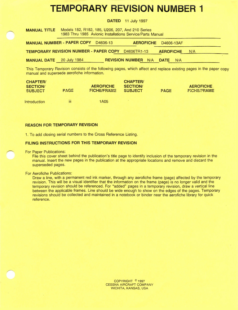
TEMPORARY REVISION NUMBER 1
DATED 11 July 1997
MANUAL TITLE Models 182, R182, 185, U206, 207, And 210 Series
1983 Thru 1985 Avionic Installations Service/Parts Manual
MANUAL NUMBER - PAPER COPY D4606-13 AEROFICHE D4606-13AF
TEMPORARY REVISION NUMBER - PAPER COPY D4606TR1-13 AEROFICHE N/A
MANUAL DATE 20 July 1984 REVISION NUMBER N/A DATE N/A
This Temporary Revision consists of the following pages, which affect and replace existing pages in the paper copy
manual and supersede aerofiche information.
CHAPTER/ CHAPTER/
SECTION/ AEROFICHE SECTION/ AEROFICHE
SUBJECT PAGE FICHE/FRAME SUBJECT PAGE FICHE/FRAME
Introduction iii 1A05
REASON FOR TEMPORARY REVISION
1. To add closing serial numbers to the Cross Reference Listing.
FILING INSTRUCTIONS FOR THIS TEMPORARY REVISION
For Paper Publications:
File this cover sheet behind the publication's title page to identify inclusion of the temporary revision in the
manual. Insert the new pages in the publication at the appropriate locations and remove and discard the
superseded pages.
For Aerofiche Publications:
Draw a line, with a permanent red ink marker, through any aerofiche frame (page) affected by the temporary
revision. This will be a visual identifier that the information on the frame (page) is no longer valid and the
temporary revision should be referenced. For "added" pages in a temporary revision, draw a vertical line
between the applicable frames. Line should be wide enough to show on the edges of the pages. Temporary
revisions should be collected and maintained in a notebook or binder near the aerofiche library for quick
reference.
COPYRIGHT ® 1997
CESSNA AIRCRAFT COMPANY
WICHITA, KANSAS, USA
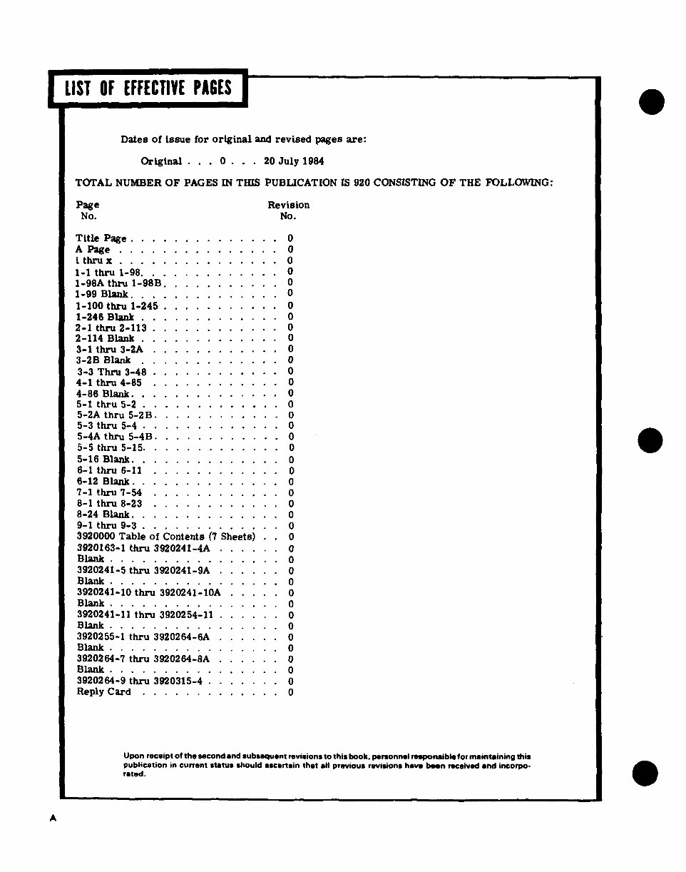
LIST OF EFFECTIVE PAGES
Dates of issue for original and revised pages are:
Original .. . 0 . . 20 July 1984
TOTAL NUMBER OF PAGES IN THIS PUBLICATION IS 920 CONSISTING OF THE FOLLOWING:
Page Revision
No. No.
Title Page ............. 0
A Page ...... ...... .. 0
i thru x . . . . . . . . . . . . . .. 0
1-1 thru 1-98 . ............ 0
1-98A thru 1-98B .... ..... 0
1-99 Blank. ........ ..... 0
1-100 thru 1-245 ........... 0
1-246 Blank ............ 0
2-1 thru 2-113 . .......... 0
2-114 Blank .. .......... 0
3-1 thru 3-2A ........... 0
3-2B Blank ............. 0
3-3 Thru 3-48 .. .......... 0
4-1 thru 4-85 ...... ...... 0
4-86 Blank .............. 0
5-1 thru 5-2 ............. 0
5-2A thru 5-2B. ........... 0
5-3 thru 5-4 ... .......... 0
5-4A thru 5-4B ............ 0
5-5 thru 5-15. ... .. . ... . . .. 0
5-16 Blank. ........... . 0
6-1 thru 6-11 ............ 0
6-12 Blank. . . . . . . . . . . . . . 0
7-1 thru 7-54 ...... ...... 0
8-1 thru 8-23 .... ....... 0
8-24 Blank. . . .. . .. .. . .. 0
9-1 thru 9-3 ............. 0
3920000 Table of Contents (7 Sheets) .
3920163-1 thru 3920241-4A ..... 0
Blank ...... . . . . . .... 0
3920241-5 thru 3920241-9A . ..... 0
Blank ....... . . . . .... 0
3920241-10 thru 3920241-10A ... . 0
Blank. ............... 0
3920241-11 thru 3920254-11 . ..... 0
Blank . .. ............ 0
3920255-1 thru 3920264-6A ...... 0
Blank . ... . . . . . . . . . . . . 0
3920264-7 thru 3920264-8A ...... 0
Blank. ............. 0
3920264-9 thru 3920315-4 ....... 0
Reply Card... ........... 0
Upon receipt of the second and subsequent revisions to this book. personnel reponsible for maintaining this
publication in current status should ascertain that all previous revisions have been received and incorpo-
rated.
A
Avionic Installations Service/Parts Manual
FOREWORD
This manual provides the radio service technician with service information, illustrated parts breakdown
and wiring diagrams pertaining to avionics equipment installed in Cessna 182, R182, 185, U206,
207 and 210 series aircraft. The catalog is separated into the following nine sections:
Section I - Sperry-Crafted Avionics Equipment
Section II - Vendor-Crafted Avionics Equipment
Section III - Antenna Systems
Section IV - Audio Systems
Section V - Miscellaneous Avionics Equipment
Section VI - Avionics Loading Charts
Section VII - Autopilot Rigging Procedures
Section VI - Numerical Index
Section IX - Avionics Wiring Diagrams
The table of contents will enable the readers to find the information necessary to check wiring installa-
tions and parts required for any particular radio.
Avionic Installations Service/Parts Manual
IMPORTANT INFORMATION CONCERNING
KEEPING CESSNA PULICATIONS CURRENT
The information in this manual is based on data available at the time for publication, and is supple-
mented and kept current to Cessna Dealers by Customer Care Service Information Letters, Customer
Care News Letters, and Customer Care Owner Advisory Letters published by Cessna Aircrat Com-
pany. In addition to this information, your dealer has been supplied a group of vendor publications
which describe complete disassembly, overhaul, and parts breakdowns of some of the various vendor
equipment items. These vendor publications are all kept current by issuing Vendor Service Bulletins,
etc., to Cessna Aircraft Company, which in turn reissues them under Cessna Vendor Service Bulletin
Notices to all appropriate dealers.
Further, this publication is also kept current in the-following two ways:
1. REVISIONS/CHANGES. These are issued to the dealers by Cessna Aircraft Company for
this publication as required, and include only pages that require updating.
2. REISSUE. Manual is reissued to dealers as required, and is a complete manual incorporat-
ing all the latest information and outstanding revisions/changes. It supersedes and re-
places previous issue(s).
REVISIONS/CHANGES and REISSUES can be purchased from your Cessna Dealer or directly from
the Cessna Supply Division, SPA Dept. 703, Cessna Aircraft Company, 5800 East Pawnee, Wichita,
Kansas 67201.
All supplemental service information concerning this manual is supplied to all appropriate Cessna
Dealers so that they have the latest authoritative recommendations for servicing these Cessna air-
craft. Therefore, it is recommended that Cessna owners utilize the knowledge and experience of the
factory-trained Dealer Service Organization.
CUSTOMER CARE SUPPLIES AND PUBLICATIONS CATALOG
A Customer Care Supplies and Publications Catalog is available from your Cessna Dealer or directly
from the Cessna Supply Division, SPA Dept. 703, Cessna Aircraft Company. 5800 East Pawnee,
Wichita, Kansas 67201. This catalog lists all publications and Customer Care Supplies available from
Cessna for prior year models as well as new products. To maintain this catalog in a current status, it
is revised quarterly and issued on Aerofiche with the quarterly Service Information Summaries.
CUSTOMER COMMENTS ON MANUAL
Cessna Aircraft Company has endeavored to furnish you with an accurate, useful, up-to-date man-
ual. This manual can be improved with your help. Please use the return card, provided with your
manual, to report any errors, discrepancies, and omissions in this manual as well as any general
comments you wish to make.
Avionic Installations Service/Parts Manual
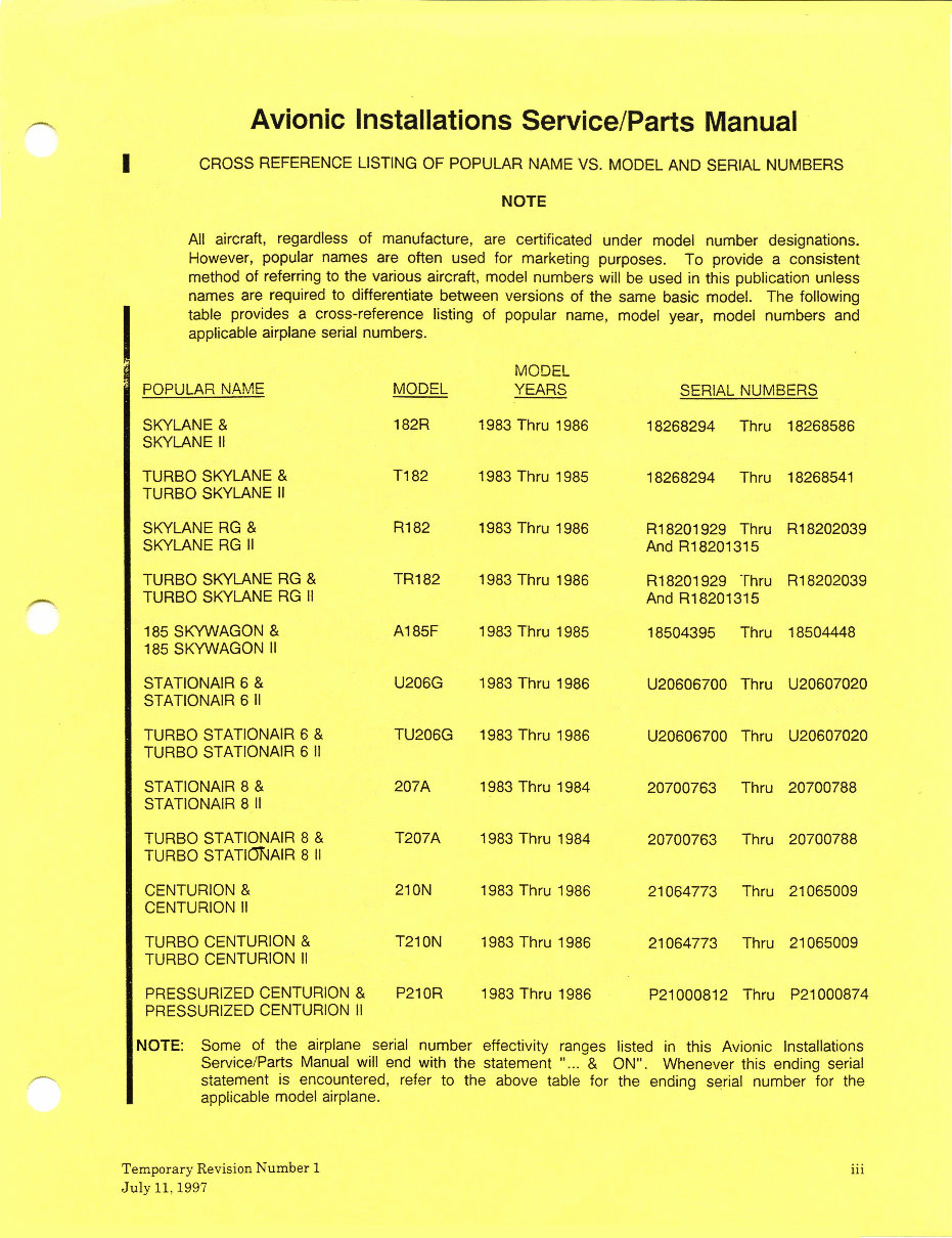
CROSS REFERENCE LISTING OF POPULAR NAME VS. MODEL AND SERIAL NUMBERS
NOTE
All aircraft, regardless of manufacture, are certificated under model number designations.
However, popular names are often used for marketing purposes. To provide a consistent
method of referring to the various aircraft, model numbers will be used in this publication unless
names are required to differentiate between versions of the same basic model. The following
table provides a cross-reference listing of popular name, model year, model numbers and
applicable airplane serial numbers.
MODEL
POPULAR NAME MODEL YEARS SERIAL NUMBERS
SKYLANE & 182R 1983 Thru 1986 18268294 Thru 18268586
SKYLANE II
TURBO SKYLANE & T182 1983 Thru 1985 18268294 Thru 18268541
TURBO SKYLANE II
SKYLANE RG & R182 1983 Thru 1986 R18201929 Thru R18202039
SKYLANE RG II And R18201315
TURBO SKYLANE RG & TR182 1983 Thru 1986 R18201929 Thru R18202039
TURBO SKYLANE RG II And R18201315
185 SKYWAGON & A185F 1983 Thru 1985 18504395 Thru 18504448
185 SKYWAGON II
STATIONAIR 6 & U206G 1983 Thru 1986 U20606700 Thru U20607020
STATIONAIR 6 II
TURBO STATIONAIR 6 & TU206G 1983 Thru 1986 U20606700 Thru U20607020
TURBO STATIONAIR 6 II
STATIONAIR 8 & 207A 1983 Thru 1984 20700763 Thru 20700788
STATIONAIR 8 II
TURBO STATIONAIR 8 & T207A 1983 Thru 1984 20700763 Thru 20700788
TURBO STATIONAIR 8 II
CENTURION & 210N 1983 Thru 1986 21064773 Thru 21065009
CENTURION II
TURBO CENTURION & T210N 1983 Thru 1986 21064773 Thru 21065009
TURBO CENTURION II
PRESSURIZED CENTURION & P210R 1983 Thru 1986 P21000812 Thru P21000874
PRESSURIZED CENTURION II
NOTE: Some of the airplane serial number effectivity ranges listed in this Avionic Installations
Service/Parts Manual will end with the statement "... & ON". Whenever this ending serial
statement is encountered, refer to the above table for the ending serial number for the
applicable model airplane.
Temporary Revision Number 1 iii
July 11, 1997
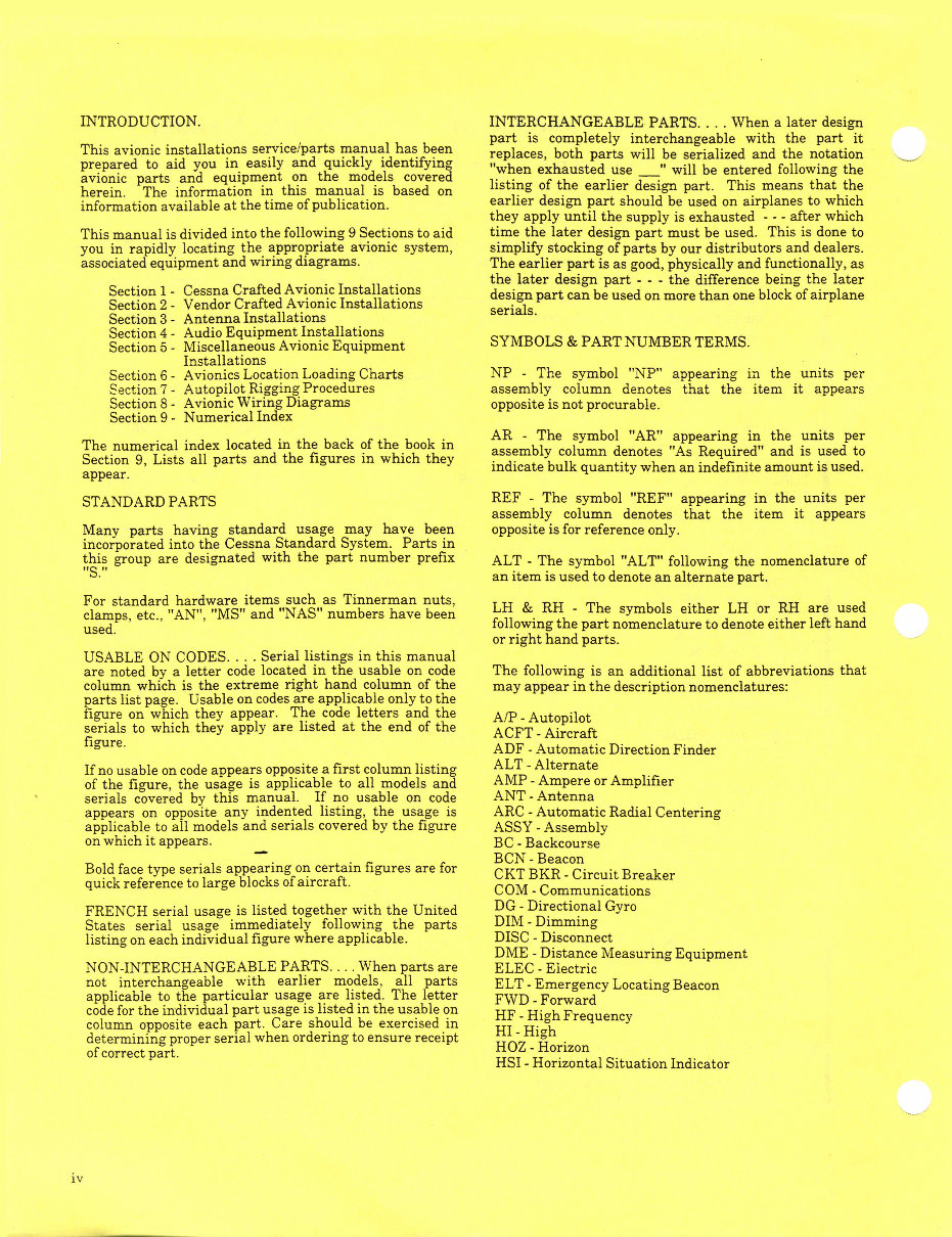
INTRODUCTION. INTERCHANGEABLE PARTS.... When a later design
part is completely interchangeable with the part it
This avionic installations service/parts manual has been replaces, both parts will be serialized and the notation
prepared to aid you in easily and quickly identifying "when exhausted use " will be entered following the
avionic parts and equipment on the models covered
herein. The information in this manual is based on listing of the earlier design part. This means that the
information available at the time of publication. earlier design part should be used on airplanes to which
they apply until the supply is exhausted --- after which
This manual is divided into the following 9 Sections to aid time the later design part must be used. This is done to
you in rapidly locating the appropriate avionic system, simplify stocking of parts by our distributors and dealers.
associated equipment and wiring diagrams. The earlier part is as good, physically and functionally, as
the later design part --- the difference being the later
Section 1 - Cessna Crafted Avionic Installations design part can be used on more than one block of airplane
Section 2 - Vendor Crafted Avionic Installations serials.
Section 3 - Antenna Installations
Section 4 - Audio Equipment Installations
Section 5 - Miscellaneous Avionic Equipment SYMBOLS & PART NUMBER TERMS.
Installations
Section 6- Avionics Location Loading Charts NP - The symbol "NP" appearing in the units per
Section 7 - Autopilot Rigging Procedures assembly column denotes that the item it appears
Section 8 - Avionic Wiring Diagrams opposite is not procurable.
Section 9 - Numerical Index
AR - The symbol "AR" appearing in the units per
The numerical index located in the back of the book in assembly column denotes "As Required and is used to
assembly column denotes "As Required" and is used to
Section 9, Lists all parts and the figures in which they
indicate bulk quantity when an indefinite amount is used.
appear.
STANDARD PARTS REF - The symbol "REF" appearing in the units per
assembly column denotes that the item it appears
Many parts having standard usage may have been opposite is for reference only.
incorporated into the Cessna Standard System. Parts in
this group are designated with the part number prefix ALT - The symbol "ALT" following the nomenclature of
"S." an item is used to denote an alternate part.
For standard hardware items such as Tinnerman nuts,
clamps, etc., "AN", "MS" and "NAS" numbers have been LH & RH- The symbols either LH or RH are used
used. following the part nomenclature to denote either left hand
or right hand parts.
USABLE ON CODES.... Serial listings in this manual
are noted by a letter code located in the usable on code The following is an additional list of abbreviations that
column which is the extreme right hand column of the may appear in the description nomenclatures:
parts list page. Usable on codes are applicable only to the
figure on which they appear. The code letters and the A/P - Autopilot
serials to which they apply are listed at the end of the ACFT- Aircraft
figure.
ADF - Automatic Direction Finder
If no usable on code appears opposite a first column listing ALT - Alternate
of the figure, the usage is applicable to all models and AMP - Ampere or Amplifier
serials covered by this manual. If no usable on code ANT- Antenna
appears on opposite any indented listing, the usage is ARC - Automatic Radial Centering
applicable to all models and serials covered by the figure ASSY - Assembly
on which it appears. BC - Backcourse
BCN - Beacon
Bold face type serials appearing on certain figures are for CKT BKR - Circuit Breaker
quick reference to large blocks of aircraft.CO
COM - Communications
FRENCH serial usage is listed together with the United DG- Directional Gyro
States serial usage immediately following the parts DIM - Dimming
listing on each individual figure where applicable. DISC - Disconnect
DME - Distance Measuring Equipment
NON-INTERCHANGEABLE PARTS.... When parts are ELEC - Electric
not interchangeable with earlier models, all parts ELT - Emergency Locating Beacon
applicable to the particular usage are listed. The letter FWD - Forward
code for the individual part usage is listed in the usable on High Freuency
column opposite each part. Care should be exercised in -
determining proper serial when ordering to ensure receipt
of correct part. HOZ - Horizon
HSI - Horizontal Situation Indicator
iv
Avionic Installations Service/Parts Manual
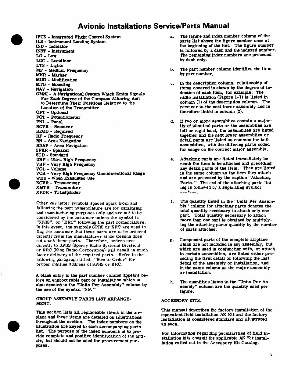
IFCS - Integrated Flight Control System a. The figure and index number column of the
ILS - Instrument Landing System parts list shows the figure number once at
IND - Indicator the beginning of the list. The figure number
INST - Instrument is followed by a dash and the indexed number.
LO - Low The remaining index numbers are preceded
LOC - Localizer by dash only.
LTS - Lights
MF - Medium Frequency b. The part number column identifies the item
MKR - Marker by part number,
MOD- Modification
MTG - Mounting c. In the description column, relationship of
NAV - Navigation items covered is shown by the degree of in-
OMNI - A Navigational System Which Emits Signals dention of each item, for example: The
For Each Degree of the Compass Allowing Acft radio installation (Figure 1-1) is listed in
to Determine Their Positions Relative to the column (1) of the description column. The
Location of the Transmitter. receiver is the next lower assembly and is
OPT - Optional therefore listed in column (2).
POT - Potentiometer
PNL - Panel d. If two or more assemblies contain a major-
RCVR - Receiver ity of identical parts or the assemblies are
REQD - Required left or right hand, the assemblies are listed
RF - Radio Frequency together and the next lower assemblies or
RN - Area Navigation detail parts are listed as common for both
RNAV - Area Navigation assemblies, with the differing parts coded
SPKR - Speaker for usage on the correct major assembly.
STD - Standard
UHF - Ultra High Frequency e. Attaching parts are listed immediately be-
VHF - Very High Frequency neath the item to be attached and preceding
VOL - Volume any detail parts of the item. They are listed
VOR - Very High Frequency Omnidirectional Range in the same column as the item they attach
WEU - When Exhausted Use and are preceded by the caption "Attaching
XCVR - Transceiver Parts." The end of the attaching parts list-
XMTR - Transmitter ing is followed by a separating symbol
XPDR - Transponder -- *---.
Other key letter symbols spaced apart from and f The quantity listed in the "Units Per Assem-
following the part nomenclature are for cataloging bly" column for attaching parts denotes the
and manufacturing purposes only and are not to be total quantity necessary to attach only one
considered by the customer unless the symbol is
"SPRS", or "KRC" following the part nomenclature, more than one part is obtained by multiply-
In this event, the symbols SPRS or KRC are used to ing the attaching parts quantity by the number
flag the customer that these parts are to be ordered of parts attached.
directly from the manufacturer since Cessna does
not stock these parts. Therefore, orders sent g. Component parts of the complete airplane
directly to SPRS (Sperry Radio Systems Division) which are not included in any assembly, but
or KRC (King Radio Corporation) will result in much which are used in conjunction with, or attach
faster delivery of the required parts. Refer to the to certain assemblies, are listed either pre-
following paragraph titled, "How to Order" for ceding the first detail or following the last
proper mailing address of SPRS or KRC. detail of the assembly or installation, and
in the same column as the major assembly
or installation.
A blank entry in the part number column appears be- or installation.
fore an unprocurable part or installation which is h. The quantities listed in the "Units Per As-
also denoted in the "Units Per Assembly" column by sembly" column are the quantity used per
the use of the symbol "NP. " figure.
GROUP ASSEMBLY PARTS LIST ARRANGE- ACCESSORY KITS.
MENT.
This manual describes the factory installation of the
This section lists all replaceable items in the air- This manual describes the factory installation of the
equivalent field installation AK Kit and the factory
plane and these items are detailed on illustrations installation is considered standard and illustrated
throughout the section. The index numbers on the
as such.
illustration are keyed to each accompanying parts
list. The purpose of the index numbers is to pro-
list. The purpose of the index numbers is to pro- For information regarding peculiarities of field in-
vide complete and positive identification of the arti- stallation kits consult the applicable AK Kit instal-
cle, but should not be used for procurement pur- lation called out in the Accessory Kit Catalog.
poses.
v
Avionic Installations Service/Parts Manual
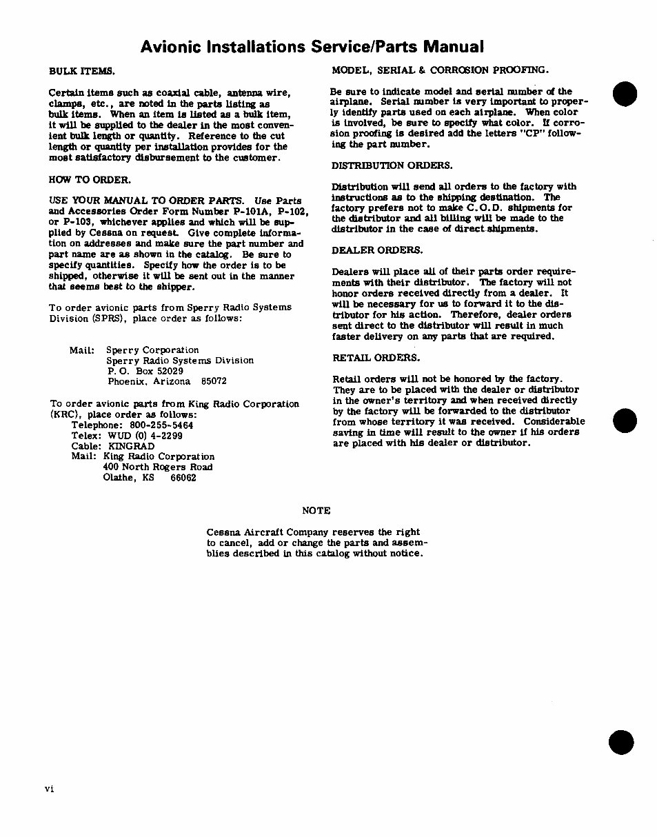
BULK ITEMS. MODEL, SERIAL & CORROSION PROOFING.
Certain items such as coaxial cable, antenna wire, Be sure to indicate model and serial number of the
clamps, etc., are noted in the parts listing as airplane. Serial number is very important to proper-
bulk items. When an item is listed as a bulk item, ly identify parts used on each airplane. When color
it will be supplied to the dealer in the most conven- is involved, be sure to specify what color. If corro-
ient bulk length or quantity. Reference to the cut sion proofing is desired add the letters "CP" follow-
length or quantity per installation provides for the ing the part number.
most satisfactory disbursement to the customer.
DISTRIBUTION ORDERS.
HOW TO ORDER.
Distribution will send all orders to the factory with
USE YOUR MANUAL TO ORDER PARTS. Use Parts instructions as to the shipping destination. The
and Accessories Order Form Number P-101A, P-102, factory prefers not to make C.O.D. shipments for
or P-103, whichever applies and which will be sup- the distributor and all billing will be made to the
plied by Cessna on request Give complete informa- distributor in the case of direct shipments.
tion on addresses and make sure the part number and
part name are as shown in the catalog. Be sure to DEALER ORDERS.
specify quantities. Specify how the order is to be
shipped, otherwise it will be sent out in the manner Dealers will place all of their parts order require-
that seems best to the shipper. ments with their distributor. The factory will not
honor orders received directly from a dealer. It
To order avionic parts from Sperry Radio Systems will be necessary for us to forward it to the dis-
Division (SPRS), place order as follows: tributor for his action. Therefore, dealer orders
sent direct to the distributor will result in much
faster delivery on any parts that are required.
Mail: Sperry Corporation
Sperry Radio Systems Division RETAIL ORDERS.
P. O. Box 52029
Phoenix, Arizona 85072 Retail orders will not be honored by the factory.
They are to be placed with the dealer or distributor
To order avionic parts from King Radio Corporation in the owner's territory and when received directly
(KRC), place order as follows: by the factory will be forwarded to the distributor
Telephone: 800-255-5464 from whose territory it was received. Considerable
Telex: WUD (0) 4-2299 saving in time will result to the owner if his orders
Cable: KINGRAD are placed with his dealer or distributor.
Mail: King Radio Corporation
400 North Rogers Road
Olathe, KS 66062
NOTE
Cessna Aircraft Company reserves the right
to cancel, add or change the parts and assem-
blies described in this catalog without notice.
vi
You're Reading a Preview
What's Included?
Fast Download Speeds
Online & Offline Access
Access PDF Contents & Bookmarks
Full Search Facility
Print one or all pages of your manual
$44.99
Viewed 56 Times Today


Secure transaction
What's Included?
Fast Download Speeds
Online & Offline Access
Access PDF Contents & Bookmarks
Full Search Facility
Print one or all pages of your manual
$44.99
This Avionic Installations Service/Parts Manual covers the 1983-1985 models 182, R182, 185, U206, 207, and 210 series where applicable. The FAA approval has been obtained on the technical data in this publication that affects airplane type design. This manual supersedes and replaces all D4604-13 Avionic Installations Service/Parts Manuals dated 20 August 1982 (D4606-13) (RGI-50-4/98).


