

Cessna 310R IPC parts manual P533-15-12 310 R
What's Included?
Fast Download Speeds
Online & Offline Access
Access PDF Contents & Bookmarks
Full Search Facility
Print one or all pages of your manual
A Textron Company
Illustrated Parts Catalog
197 tru 18
MOEI30
TURBO 310R~~
Member of GAMA
COPYRIGHT © 1975
CESSNA AIRCRAFT COMPANY
WICHITA, KANSAS, USA
P533-15-12
1 OCTOBER 1975
REVISION 15 3 JULY 2006
CESSNA AIRCRAFT COMPANY
MODEL 310OR
ILLUSTRATED PARTS CATALOG
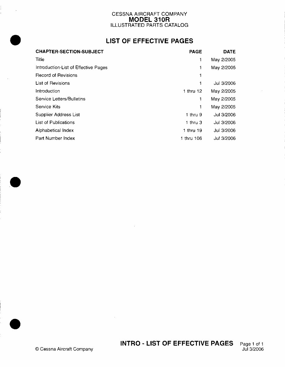
LIST OF EFFECTIVE PAGES
CHAPTER-SECTION-SUBJECT
Title
Introduction-List of Effective Pages
Record of Revisions
List of Revisions
Introduction
Service Letters/Bulletins
Service Kits
Supplier Address List
List of Publications
Alphabetical Index
Part Number Index
© Cessna Aircraft Company
PAGE DATE
1 May 2/2005
1 May 2/2005
1
1 Jul 3/2006
1 thru 12 May 2/2005
1 May 2/2005
1 May 2/2005
1 thru 9 Jul 3/2006
1 thru 3 Jul 3/2006
1 thru 19 Jul 3/2006
1 thru 106 Jul 3/2006
INTRO - LIST OF EFFECTIVE PAGES Page 1 of 1
Jul 3/2006
CESSNA AIRCRAFT COMPANY
MODEL 310OR
ILLUSTRATED PARTS CATALOG
RECORD OF REVISIONS
DATE PAGE
REMOVED NUMBER
REVISION DATE DATE PAGE
NUMBER jINSERTED jREMOVED NUMBER
4 + 4
+ + 4
.4. -4. 4
4 + *
4 4
I. I. I
I 4 4
4 4
4 4 4
4 4
4 4 4
REVISION
NUMBER
DATE
INSERTED
CESSNA AIRCRAFT COMPANY
MODEL 310OR
ILLUSTRATED PARTS CATALOG
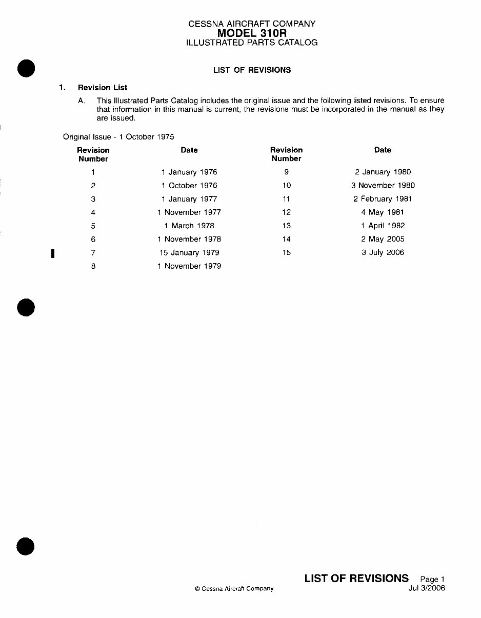
LIST OF REVISIONS
1.Revision List
A. This Illustrated Parts Catalog includes the original issue and the following listed revisions. To ensure
that information in this manual is current, the revisions must be incorporated in the manual as they
are issued.
Original Issue - 1 October 1975
Revision
Number
1 1Ja
2 1 0
3 1 Ja
4
5
6
7
8
1 No~
1 N
1 No,
15 J;
1 No,
Date
inuary 1976
c-tober 1976
inuary 1977
vember 1977
l1arch 1978
~tember 1978
anuary 1979
vember 1979
Revision
N umber
9
10
11
12
13
14
1 5
Date
2 January 1980
3 November 1980
2 February 1981
4 May 1981
1 April 1982
2 May 2005
3 July 2006
©D Cessna Aircraft Company
LIST OF REVISIONS Page 1
Jul 3/2006
I
CESSNA AIRCRAFT COMPANY
MODEL 310OR
ILLUSTRATED PARTS CATALOG
INTRODUCTION
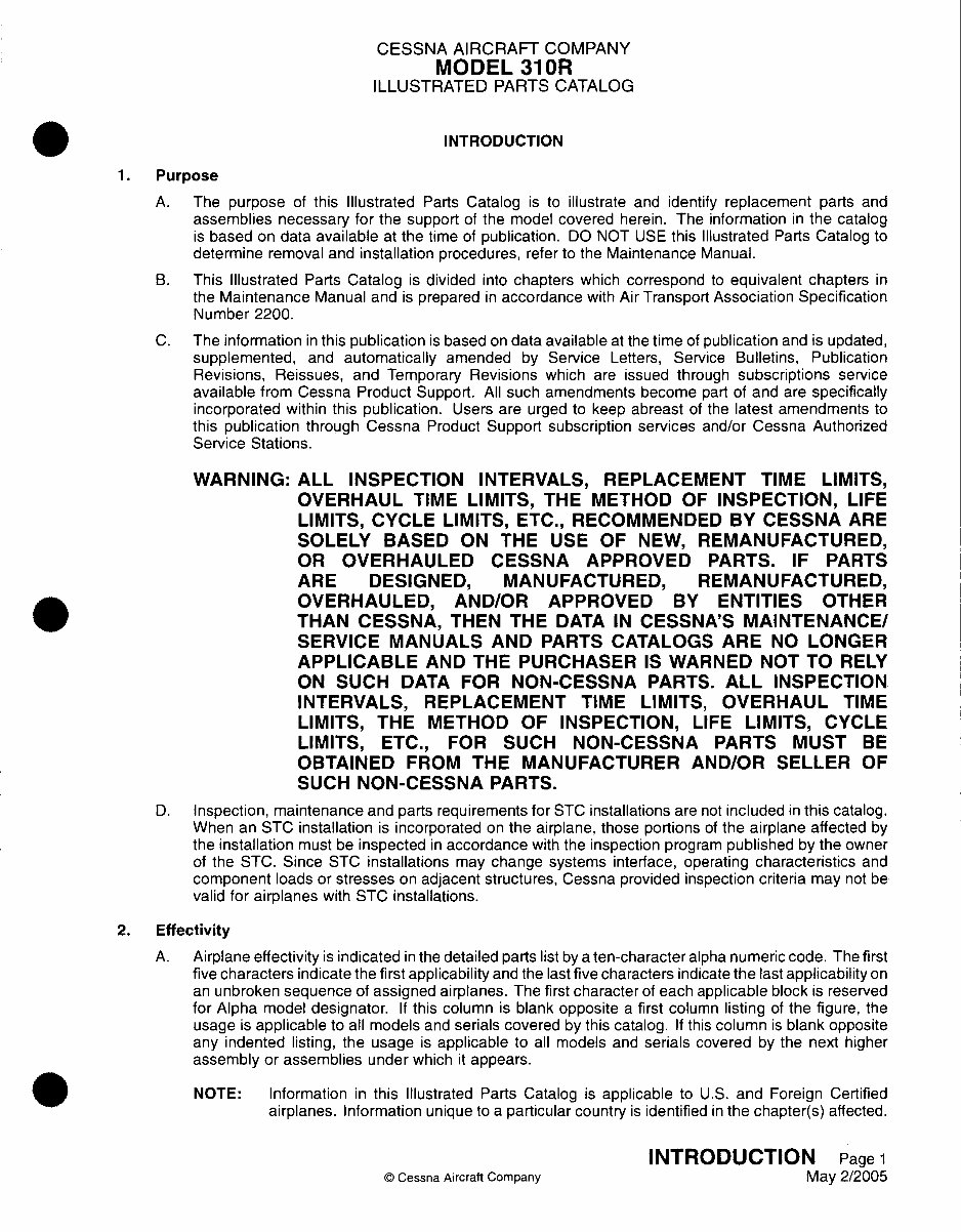
1. Purpose
A. The purpose of this Illustrated Parts Catalog is to illustrate and identify replacement parts and
assemblies necessary for the support of the model covered herein. The information in the catalog
is based on data available at the time of publication. DO NOT USE this Illustrated Parts Catalog to
determine removal and installation procedures, refer to the Maintenance Manual.
B. This Illustrated Parts Catalog is divided into chapters which correspond to equivalent chapters in
the Maintenance Manual and is prepared in accordance with Air Transport Association Specification
Number 2200.
C. The information in this publication is based on data available at the time of publication and is updated,
supplemented, and automatically amended by Service Letters, Service Bulletins, Publication
Revisions, Reissues, and Temporary Revisions which are issued through subscriptions service
available from Cessna Product Support. All such amendments become part of and are specifically
incorporated within this publication. Users are urged to keep abreast of the latest amendments to
this publication through Cessna Product Support subscription services and/or Cessna Authorized
Service Stations.
WARNING: ALL INSPECTION INTERVALS, REPLACEMENT TIME LIMITS,
OVERHAUL TIME LIMITS, THE METHOD OF INSPECTION, LIFE
LIMITS, CYCLE LIMITS, ETC., RECOMMENDED BY CESSNA ARE
SOLELY BASED ON THE USE OF NEW, REMANUFACTURED,
OR OVERHAULED CESSNA APPROVED PARTS. IF PARTS
ARE DESIGNED, MANUFACTURED, REMANUFACTURED,
OVERHAULED, AND/OR APPROVED BY ENTITIES OTHER
THAN CESSNA, THEN THE DATA IN CESSNA'S MAINTENANCE/
SERVICE MANUALS AND PARTS CATALOGS ARE NO LONGER
APPLICABLE AND THE PURCHASER IS WARNED NOT TO RELY
ON SUCH DATA FOR NON-CESSNA PARTS. ALL INSPECTION
INTERVALS, REPLACEMENT TIME LIMITS, OVERHAUL TIME
LIMITS, THE METHOD OF INSPECTION, LIFE LIMITS, CYCLE
LIMITS, ETC., FOR SUCH NON-CESSNA PARTS MUST BE
OBTAINED FROM THE MANUFACTURER AND/OR SELLER OF
SUCH NON-CESSNA PARTS.
0. Inspection, maintenance and parts requirements for STC installations are not included in this catalog.
When an STC installation is incorporated on the airplane, those portions of the airplane affected by
the installation must be inspected in accordance with the inspection program published by the owner
of the STC. Since STC installations may change systems interface, operating characteristics and
component loads or stresses on adjacent structures, Cessna provided inspection criteria may not be
valid for airplanes with STC installations.
2. Effectivity
A. Airplane eff ectivity is indicated in the detailed parts list by a ten-character alpha numeric code. The first
five characters indicate the first applicability and the last five characters indicate the last applicability on
an unbroken sequence of assigned airplanes. The first character of each applicable block is reserved
for Alpha model designator. If this column is blank opposite a first column listing of the figure, the
usage is applicable to all models and serials covered by this catalog. If this column is blank opposite
any indented listing, the usage is applicable to all models and serials covered by the next higher
assembly or assemblies under which it appears.
NOTE: Information in this Illustrated Parts Catalog is applicable to U.S. and Foreign Certified
airplanes. Information unique to a particular country is identified in the chapter(s) affected.
INTRODUCTION Page 1
(D Cessna Aircraft Company May 2/2005
CESSNA AIRCRAFT COMPANY
MODEL 310OR
ILLUSTRATED PARTS CATALOG
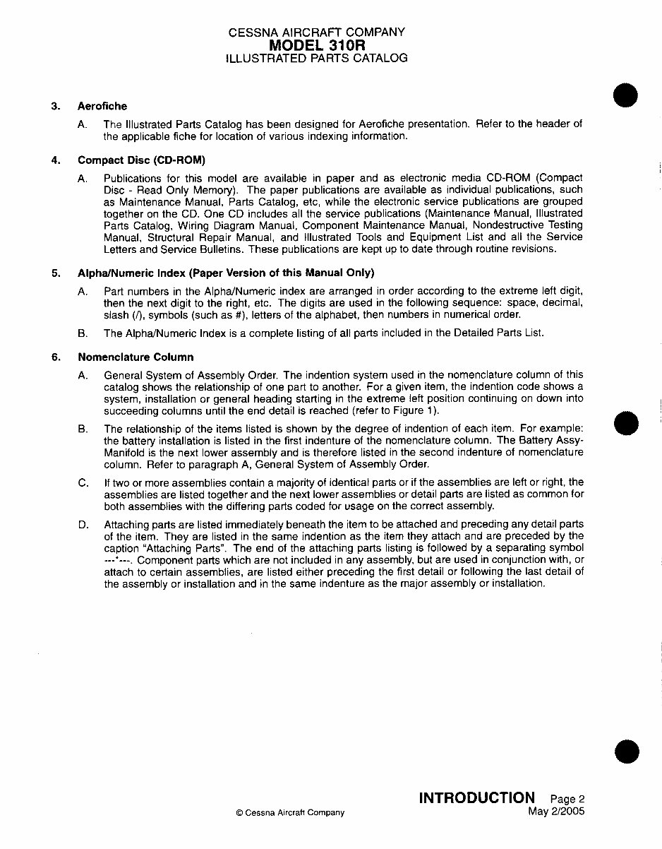
3. Aerofiche
A. The Illustrated Parts Catalog has been designed for Aerofiche presentation. Refer to the header of
the applicable fiche for location of various indexing information.
4. Compact Disc (CD-ROM)
A. Publications for this model are available in paper and as electronic media CD-ROM (Compact
Disc - Read Only Memory). The paper publications are available as individual publications, such
as Maintenance Manual, Parts Catalog, etc, while the electronic service publications are grouped
together on the CD. One CD includes all the service publications (Maintenance Manual, Illustrated
Parts Catalog, Wiring Diagram Manual, Component Maintenance Manual, Nondestructive Testing
Manual, Structural Repair Manual, and Illustrated Tools and Equipment List and all the Service
Letters and Service Bulletins. These publications are kept up to date through routine revisions.
5. Alpha/Numeric Index (Paper Version of this Manual Only)
A. Part numbers in the Alpha/Numeric index are arranged in order according to the extreme left digit,
then the next digit to the right, etc. The digits are used in the following sequence: space, decimal,
slash (I), symbols (such as #), letters of the alphabet, then numbers in numerical order.
B. The Alpha/Numeric Index is a complete listing of all parts included in the Detailed Parts List.
6. Nomenclature Column
A. General System of Assembly Order. The indention system used in the nomenclature column of this
catalog shows the relationship of one part to another. For a given item, the indention code shows a
system, installation or general heading starting in the extreme left position continuing on down into
succeeding columns until the end detail is reached (refer to Figure 1).
B. The relationship of the items listed is shown by the degree of indention of each item. For example:
the battery installation is listed in the first indenture of the nomenclature column. The Battery Assy-
Manifold is the next lower assembly and is therefore listed in the second indenture of nomenclature
column. Refer to paragraph A, General System of Assembly Order.
C. If two or more assemblies contain a majority of identical parts or if the assemblies are left or right, the
assemblies are listed together and the next lower assemblies or detail parts are listed as common for
both assemblies with the differing parts coded for usage on the correct assembly.
D. Attaching parts are listed immediately beneath the item to be attached and preceding any detail parts
of the item. They are listed in the same indention as the item they attach and are preceded by the
caption "Attaching Parts'. The end of the attaching parts listing is followed by a separating symbol
--- ---- Component parts which are not included in any assembly, but are used in conjunction with, or
attach to certain assemblies, are listed either preceding the first detail or following the last detail of
the assembly or installation and in the same indenture as the major assembly or installation.
INTRODUCTION Page 2
(D Cessna Aircraft Company May 2/2005
CESSNA AIRCRAFT COMPANY
MODEL 310OR
ILLUSTRATED PARTS CATALOG
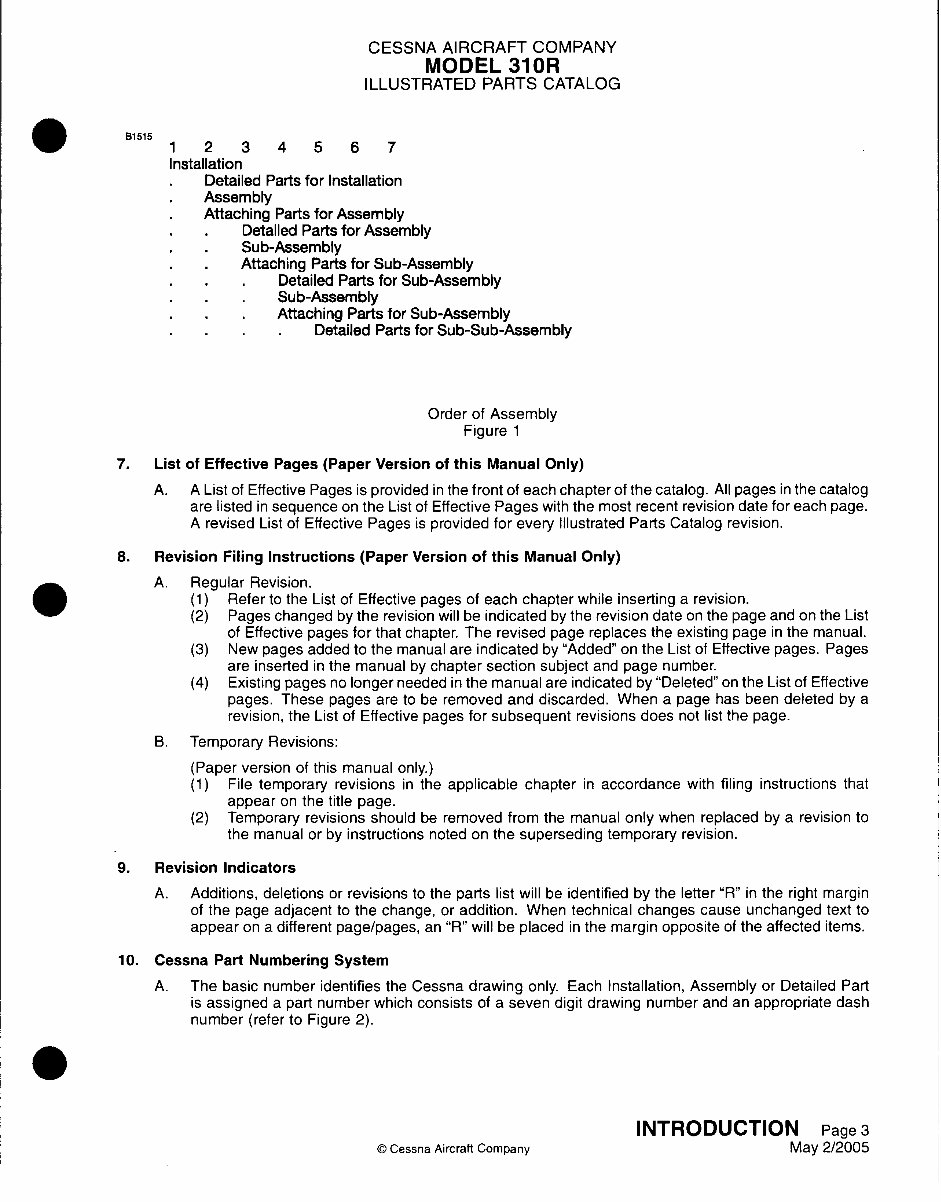
13i 515
1 2 3 4 5 6 7
Installation
* Detailed Parts for Installation
* Assembly
* Attaching Parts for Assembly
*Detailed Parts for Assembly
*Sub-Assembly
*Attaching Parts for Sub-Assembly
* ~~~Detailed Parts for Sub-Assembly
* . ~Sub-Assembly
* ~~~Attaching Parts for Sub-Assembly
* ~~~~Detailed Parts for Sub-Sub-Assembly
Order of Assembly
Figure 1
7. List of Effective Pages (Paper Version of this Manual Only)
A. A List of Eff ective Pages is provided in the f ront of each chapter of the catalog. All pages in the catalog
are listed in sequence on the List of Effective Pages with the most recent revision date for each page.
A revised List of Effective Pages is provided for every Illustrated Parts Catalog revision.
8. Revision Filing Instructions (Paper Version of this Manual Only)
A. Regular Revision.
(1) Refer to the List of Effective pages of each chapter while inserting a revision.
(2) Pages changed by the revision will be indicated by the revision date on the page and on the List
of Effective pages for that chapter. The revised page replaces the existing page in the manual.
(3) New pages added to the manual are indicated by "Added" on the List of Effective pages. Pages
are inserted in the manual by chapter section subject and page number.
(4) Existing pages no longer needed in the manual are indicated by "Deleted" on the List of Effective
pages. These pages are to be removed and discarded. When a page has been deleted by a
revision, the List of Effective pages for subsequent revisions does not list the page.
B. Temporary Revisions:
(Paper version of this manual only.)
(1) File temporary revisions in the applicable chapter in accordance with filing instructions that
appear on the title page.
(2) Temporary revisions should be removed from the manual only when replaced by a revision to
the manual or by instructions noted on the superseding temporary revision.
9. Revision Indicators
A. Additions, deletions or revisions to the parts list will be identified by the letter "R" in the right margin
of the page adjacent to the change, or addition. When technical changes cause unchanged text to
appear on a different page/pages, an "R" will be placed in the margin opposite of the affected items.
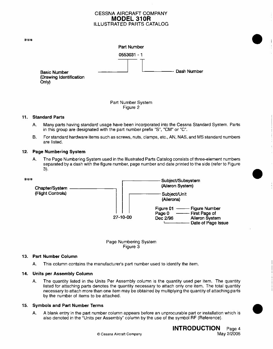
10. Cessna Part Numbering System
A. The basic number identifies the Cessna drawing only. Each Installation, Assembly or Detailed Part
is assigned a part number which consists of a seven digit drawing number and an appropriate dash
number (refer to Figure 2).
INTRODUCTION Page 3
© Cessna Aircraft Company May 2/2005
CESSNA AIRCRAFT COMPANY
MODEL 310OR
ILLUSTRATED PARTS CATALOG
B1516
Basic Number
(Drawing Identification
Only)
Part Number
0553031 -1
Dash Number
Part Number System
Figure 2
11. Standard Parts
A. Many parts having standard usage have been incorporated into the Cessna Standard System. Parts
in this group are designated with the part number prefix "S', "CM" or "C'.
B. For standard hardware items such as screws, nuts, clamps, etc., AN, NAS, and MS standard numbers
are listed.
12. Page Numbering System
A. The Page Numbering System used in the Illustrated Parts Catalog consists of three-element numbers
separated by a dash with the figure number, page number and date printed to the side (refer to Figure
3).
Chapter/System
(Flight Controls)
Subject/Subsystem
(Aileron System)
Subject/Unit
(Ailerons)
Figure 01 - Figur
D -- n ______
27-10-00
e Number
D- -n
4
IF UL~ % I II 09 I Urn J
Dec 2/96 Aileron System
I~ . Date of Page Issue
Page Numbering System
Figure 3
13. Part Number Column
A. This column contains the manufacturer's part number used to identify the item.
14. Units per Assembly Column
A. The quantity listed in the Units Per Assembly column is the quantity used per item. The quantity
listed for attaching parts denotes the quantity necessary to attach only one item. The total quantity
necessary to attach more than one item may be obtained by multiplying the quantity of attaching parts
by the number of items to be attached.
15. Symbols and Part Number Terms
A. A blank entry in the part number column appears before an unprocurable part or installation which is
also denoted in the "Units per Assembly" column by the use of the symbol RF (Reference).
INTRODUCTION Page 4
© Cessna Aircraft Company May 2/2005
B1518
CESSNA AIRCRAFT COMPANY
MODEL 310OR
ILLUSTRATED PARTS CATALOG
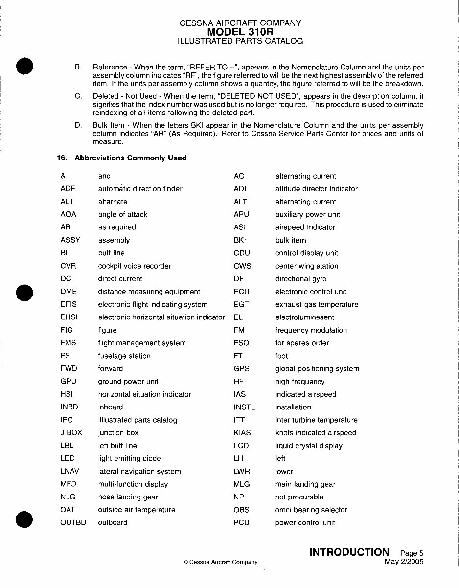
B. Reference - When the term, "REFER TO --", appears in the Nomenclature Column and the units per
assembly column indicates "RE", the figure referred to will be the next highest assembly of the referred
item. If the units per assembly column shows a quantity, the figure referred to will be the breakdown.
C. Deleted - Not Used - When the term, "DELETED NOT USED", appears in the description column, it
signifies that the index number was used but is no longer required. This procedure is used to eliminate
reindlexing of all items following the deleted part.
D. Bulk Item - When the letters BKI appear in the Nomenclature Column and the units per assembly
column indicates "AR" (As Required). Refer to Cessna Service Parts Center for prices and units of
measure.
16. Abbreviations Commonly Used
and
automatic direction finder
alternate
angle of attack
as required
assembly
butt line
cockpit voice recorder
direct current
distance measuring equipment
electronic flight indicating system
electronic horizontal situation indicator
figure
flight management system
fuselage station
forward
ground power unit
horizontal situation indicator
inboard
Illustrated parts catalog
junction box
left butt line
light emitting diode
lateral navigation system
multi-function display
nose landing gear
outside air temperature
outboard
AC
ADI
ALT
APU
ASI
BK1
CDU
CWS
DF
ECU
EGT
EL
FM
FSO
FT
GPS
HIF
lAS
INSTIL
ITT
KIAS
LCD
LH
LWR
MVLG
NP
OBS
PCU
© Cessna Aircraft Company
alternating current
attitude director indicator
alternating current
auxiliary power unit
airspeed Indicator
bulk item
control display unit
center wing station
directional gyro
electronic control unit
exhaust gas temperature
electrolumninesent
frequency modulation
for spares order
f oot
global positioning system
high frequency
indicated airspeed
installation
inter turbine temperature
knots indicated airspeed
liquid crystal display
left
lower
main landing gear
not procurable
omnni bearing selector
power control unit
INTRODUCTION Page 5
May 2/2005
ADE
ALT
AOA
AR
ASSY
BL
CVR
DC
DMVE
EFlS
EHSI
FIG
FIVS
ES
FWD
GPU
HSI
INBD
IPC
J-BOX
LBL
LED
LNAV
MED
NLG
OAT
OUTBID
CESSNA AIRCRAFT COMPANY
MODEL 310OR
ILLUSTRATED PARTS CATALOG
PSI
P/N
PTU pounds square inch
part number
R NAV area navigation
RAT ram air temperature
REF radio frequency
RH right
RPM revolutions per minute
SIB service bulletin
TACAN tactical air navigation system
terminal block
TEMP temperature
UHF ultra high frequency
USART universal synchronous/asynchronous
receiver/transmitter
VASI visual approach slope indicator
VHF very high frequency
VOR very high frequency omnidirectional
and radio range
WBA wire bundle assembly
WL water line
power transfer unit
PRESS pressure
RAM
RBL
RE
RMIV
SAT
Ss
TAS
TCAS
TR
UPR
V NAV
VG
VLF
VS1
random access memory
right butt line
reference
radio magnetic indicator
static air temperature
stabilizer station
true airspeed
traffic collision avoidance system
temporary revision
upper
vertical navigation
vertical gyro
very low frequency
vertical speed indicator
WBSA wire bundle subassembly
Ws wing station
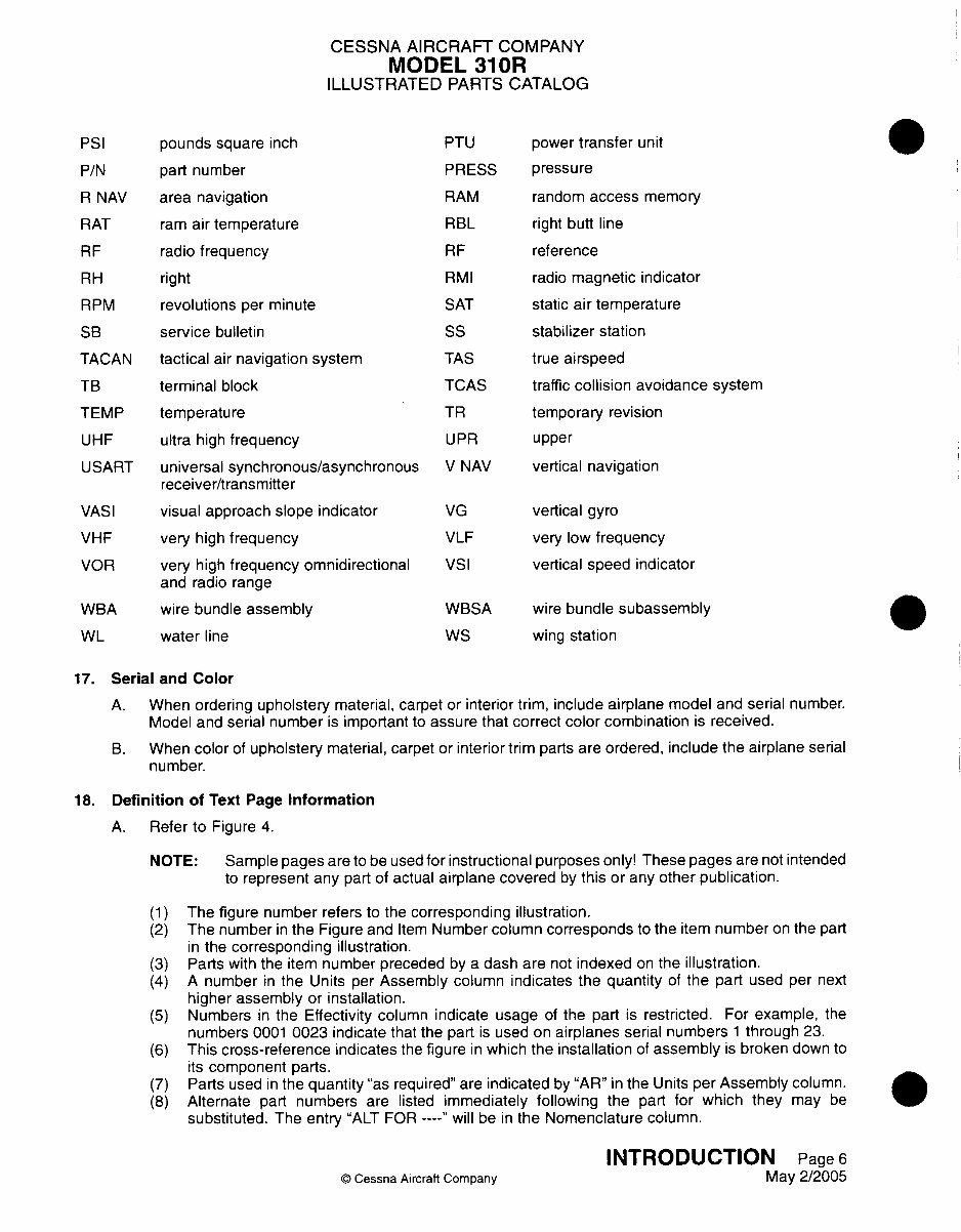
17. Serial and Color
A. When ordering upholstery material, carpet or interior trim, include airplane model and serial number.
Model and serial number is important to assure that correct color combination is received.
B. When color of upholstery material, carpet or interior trim parts are ordered, include the airplane serial
number.
18. Definition of Text Page Information
A. Refer to Figure 4.
NOTE: Sample pages are to be used for instructional purposes only! These pages are not intended
to represent any part of actual airplane covered by this or any other publication.
(1)
(2)
(3)
(4)
(5)
(6)
(7)
(8)
The figure number refers to the corresponding illustration.
The number in the Figure and Item Number column corresponds to the item number on the part
in the corresponding illustration.
Parts with the item number preceded by a dash are not indexed on the illustration.
A number in the Units per Assembly column indicates the quantity of the part used per next
higher assembly or installation.
Numbers in the Effectivity column indicate usage of the part is restricted. For example, the
numbers 0001 0023 indicate that the part is used on airplanes serial numbers 1 through 23.
This cross-reference indicates the figure in which the installation of assembly is broken down to
its component parts.
Parts used in the quantity "as required" are indicated by "AR" in the Units per Assembly column.
Alternate part numbers are listed immediately following the part for which they may be
substituted. The entry "ALT FOR -- "will be in the Nomenclature column.
© Cessna Aircraft Company
INTRODUCTION Page 6
May 2/2005
TB
You're Reading a Preview
What's Included?
Fast Download Speeds
Online & Offline Access
Access PDF Contents & Bookmarks
Full Search Facility
Print one or all pages of your manual
$52.99
Viewed 71 Times Today


Secure transaction
What's Included?
Fast Download Speeds
Online & Offline Access
Access PDF Contents & Bookmarks
Full Search Facility
Print one or all pages of your manual
$52.99
The Cessna 310R IPC parts manual P533-15-12 310 R covers the model years 1975 to 1981. It comprises 975 bookmarked, indexed, and searchable pages, with Revision 15 dated 3/06. This manual also encompasses information related to the turbo 310R. It is a valuable resource for both professional mechanics and DIY enthusiasts.


