1956-1962 Cessna 100 Series (150/172/177/180/182/185) OEM Service & Repair Manual
What's Included?
Lifetime Access
Fast Download Speeds
Online & Offline Access
Access PDF Contents & Bookmarks
Full Search Facility
Print one or all pages of your manual
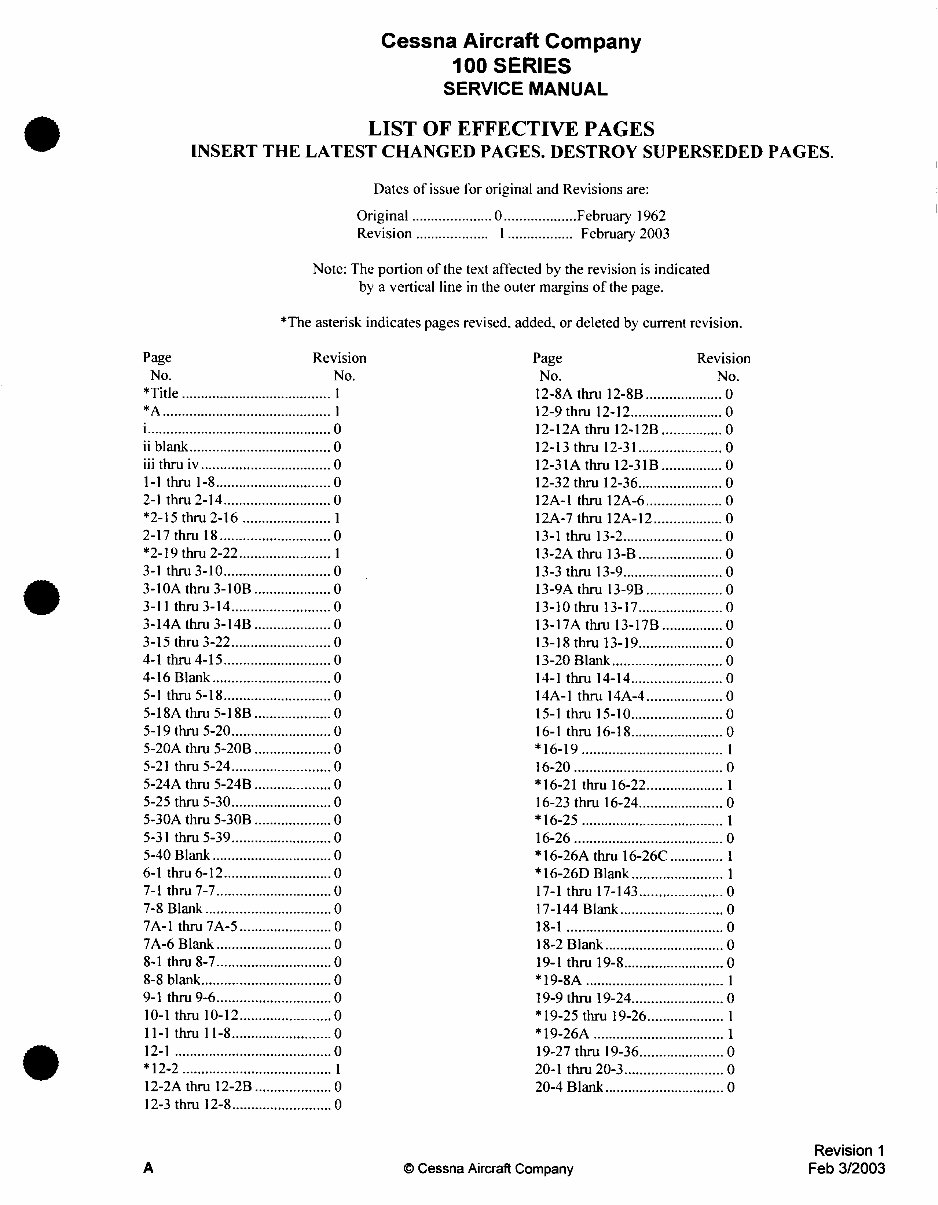
SERVICE MANUAL 100 - SERIES 150, 172, 175, 180, 182, AND 185 SERIES 1962 AND PRIOR REVISION 1 3 FEBRUARY 2003 D138R1-13 INSERT THE FOLLOWING REVISED PAGES INTO BASIC MANUAL
SERVICE MANUAL Foreword FOREWORD This manual contains recommended procedures and instructions for ground han- dling, servicing and maintaining Cessna single-engine commercial aircraft prior to 1963 models. These include the Model 150, 172, 175, 180, 182, and 185. Al- though not specifically written for earlier models which have been discontinued, much of the information can be used as a guide for maintenance of the Model 120, 140 and 170. Besides serving as a reference for the experienced mechanic, this book also covers step-by-step procedure for the less experienced man. This manual should be kept in a handy place for ready reference. If properly used, it will better enable the mechanic to maintain Cessna single-engine aircraft and thereby establish a reputation for reliable service. The material presented in this manual is divided into twenty sections. All sec- tions and their major paragraph titles are listed in the table of contents at the front of the book. A section table of contents, listing each paragraph and the page on which it appears, is located at the front of each individual section. All information, illustrations, and specifications contained in this manual are based on the latest information available at the time of publication. This information is supplemented and kept current by service letters and service news letters published by Cessna Aircraft Company. This information goes to all Cessna Dealers so that they have the latest authoritative information for servic- ing Cessna Airplanes. Therefore, Cessna recommends that all Cessna owners utilize the Cessna-trained Dealer Service Organization to the fullest, to receive the benefit of their knowledge and experience.
SERVICE MANUAL This page intentionally left blank. ii
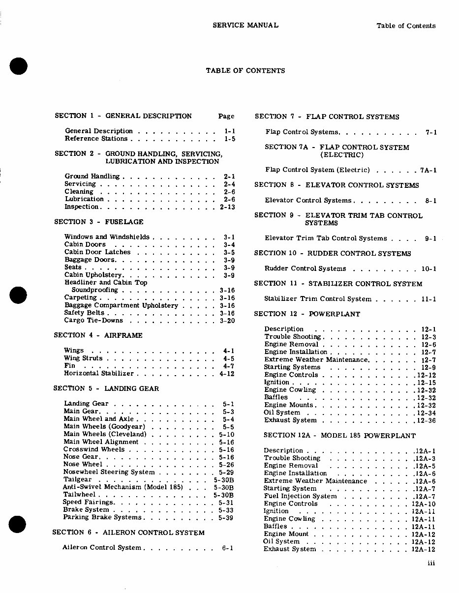
SERVICE MANUAL Table of Contents TABLE OF CONTENTS SECTION 1 - GENERAL DESCRIPTION Page SECTION 7 - FLAP CONTROL SYSTEMS General Description ........... 1-1 Flap Control Systems. .......... 7-1 Reference Stations ............ 1-5 SECTION 7A - FLAP CONTROL SYSTEM SECTION 2 - GROUND HANDLING, SERVICING, (ELECTRIC) LUBRICATION AND INSPECTION Flap Control System (Electric) ...... 7A-1 Ground Handling ............. 2-1 Servicing ................ 2-4 SECTION 8 - ELEVATOR CONTROL SYSTEMS Cleaning .... .... .. ...... 2-6 Lubrication ............... 2-6 Elevator Control Systems. ........ 8-1 Inspection. ............ ... 2-13 SECTION 9 - ELEVATOR TRIM TAB CONTROL SECTION 3 - FUSELAGE SYSTEMS Windows and Windshields ......... 3-1 Elevator Trim Tab Control Systems . . . . 9-1 Cabin Doors .............. 3-4 Cabin Door Latches ........... 3-5 SECTION 10 - RUDDER CONTROL SYSTEMS Baggage Doors ............. 3-9 Seats ................. 3-9 Rudder Control Systems ......... 10-1 Cabin Upholstery ............ 3-9 Headliner and Cabin Top SECTION 11 - STABILIZER CONTROL SYSTEM Soundproofing ........... 3-16 Carpeting. .............. . 3-16 Stabilizer Trim Control System ...... 11-1 Baggage Compartment Upholstery ..... 3-16 Safety Belts ............... 3-16 SECTION 12 - POWERPLANT Cargo Tie-Downs ............ 3-20 Description .............. 12-1 SECTION 4 - AIRFRAME Trouble Shooting. ............ 12-3 Engine Removal ............. 12-6 Wings ................. 4-1 Engine Installation ........... . 12-7 Wing Struts .............. 4-5 Extreme Weather Maintenance. ...... 12-7 Fin .................. 4-7 Starting Systems ............ 12-9 Horizontal Stabilizer ........... 4-12 Engine Controls ............. .12-12 Ignition . . . . . . . . . . . . . . .. 12-15 SECTION 5 - LANDING GEAR Engine Cowling ............. 12-32 Baffles . . . . . . . . . . . . . . . .12-32 Landing Gear .............. 5-1 Engine Mounts. ............ .12-32 Main Gear. ............... 5-3 Oil System . .......... . .12-34 Main Wheel and Axle . .......... 5-4 Exhaust System .... .... ..12-36 Main Wheels (Goodyear) ......... 5-5 Main Wheels (Cleveland) ......... 5-10 SECTION 12A - MODEL 185 POWERPLANT Main Wheel Alignment .......... 5-16 Crosswind Wheels ............ 5-16 Description ............ .12A-1 Nose Gear. ............... 5-16 Trouble Shooting ......... .12A-3 Nose Wheel ............... 5-26 Engine Removal ......... .12A-5 Nosewheel Steering System ........ 5-29 Engine Installation ........... 12A-6 Tailgear ............... 5-30B Extreme Weather Maintenance . .... 12A-6 Anti-Swivel Mechanism (Model 185) . . .5-30B Starting System ............ 12A-7 Tailwheel .............. . 5-30B Fuel Injection System ......... .12A-7 Speed Fairings. ............. 5-31 Engine Controls ......... . 12A-10 Brake System ............... 5-33 Ignition ............... 12A-11 Parking Brake Systems. ......... 5-39 Engine Cowling ............ 12A-11 Baffles . .. .. .... .. . ... 12A-11 SECTION 6 - AILERON CONTROL SYSTEM Engine Mount ............. 12A-12 Oil System. .............. 12A- Aileron Control System .......... 6-1 Exhaust System ............ 12A-12 iii
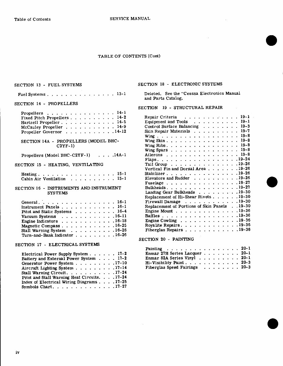
Table of Contents SERVICE MANUAL TABLE OF CONTENTS (Cont) SECTION 13 - FUEL SYSTEMS SECTION 18 - ELECTRONIC SYSTEMS Fuel Systems ............... 13-1 Deleted. See the "Cessna Electronics Manual and Parts Catalog. SECTION 14 - PROPELLERS SECTION 19 - STRUCTURAL REPAIR Propellers ............. .. 14-1 Fixed Pitch Propellers .......... 14-2 Repair Criteria ......... . 19-1 Hartzell Propeller ........... 14-5 Equipment and Tools .......... 19-1 McCauley Propeller ......... . 14-9 Control Surface Balancing ........ 19-3 Propeller Governor .......... .14-12 Skin Repair Materials .......... 19-7 Wing . . ... . .. . . .. . . .... 19-8 SECTION 14A - PROPELLERS (MODEL BHC- Wing Skin ................ 19-8 C2YF-1) Wing Ribs. ............... 19-8 Wing Spars ............... 19-8 Propellers (Model BHC-C2YF-1) . . .. 14A-1 Ailerons ................ 19-8 Flaps. ................ .19-24 SECTION 15 - HEATING, VENTILATING Tail Group .............. .19-26 Vertical Fin and Dorsal Area ....... 19-26 Heating ........... . .. ... 15-1 Stabilizer ........... ... .19-26 Cabin Air Ventilation .......... 15-1 Elevators and Rudder ......... .19-26 Fuselage .............. 19-27 SECTION 16 - INSTRUMENTS AND INSTRUMENT Bulkheads. ................ 19-27 SYSTEMS Landing Gear Bulkheads ....... . .19-30 Replacement of Hi-Shear Rivets . .... .19-30 General.. ............... 16-1 Firewall Damage ........... .19-30 Instrument Panels ............ 16-1 Replacement of Portions of Skin Panels . .19-30 Pitot and Static Systems ......... 16-4 Engine Mount .............. 19-36 Vacuum Systems .......... .16-11 Baffles ................ .19-36 Engine Indicators ............ 16-18 Engine Cowling ............ 19-36 Magnetic Compass ......... ... 16-25 Royalite Repairs ............. 19-36 Stall Warning System .......... 16-26 Fiberglas Repairs ......... ... 19-36 Turn-and-Bank Indicator ........ 16-26 SECTION 20 - PAINTING SECTION 17 - ELECTRICAL SYSTEMS Painting ... ........ ..... 20-1 Electrical Power Supply System ..... . 17-2 Enmar 27H Series Lacquer ....... . 20-1 Battery and External Power System .... 17-2 Enmar 82A Series Vinyl ......... 20-1 Generator Power System ........ .17-10 Hi-Visibility Paint .......... 20-3 Aircraft Lighting System ........ .17-14 Fiberglas Speed Fairings ........ 20-3 Stall Warning Circuit. ......... .17-24 Pitot and Stall Warning Heat Circuits. . . .17-24 Index of Electrical Wiring Diagrams .... 17-25 Symbols Chart. .............. 17-27 iv
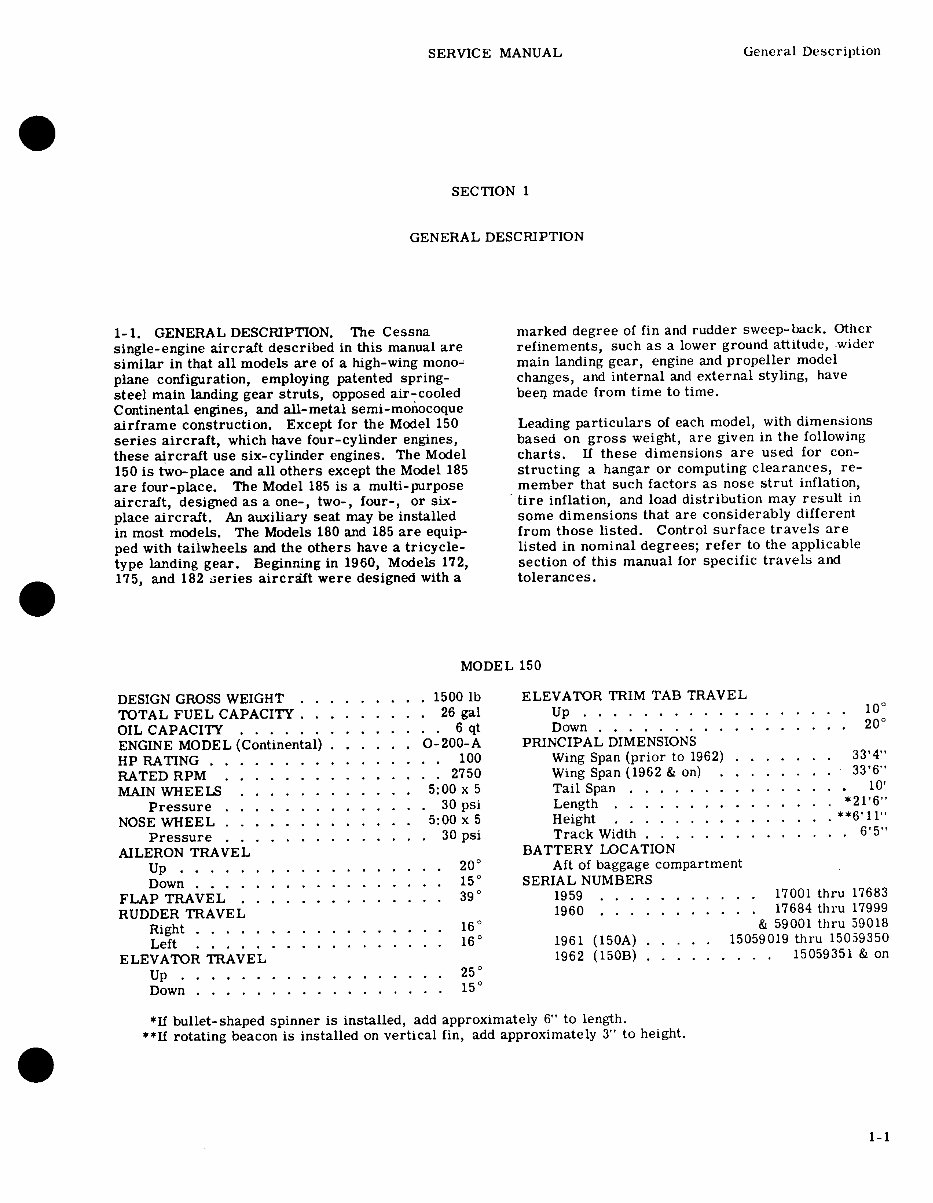
SERVICE MANUAL General Description SECTION 1 GENERAL DESCRIPTION 1-1. GENERAL DESCRIPTION. The Cessna marked degree of fin and rudder sweep-back. Other single-engine aircraft described in this manual are refinements, such as a lower ground attitude, wider similar in that all models are of a high-wing mono- main landing gear, engine and propeller model plane configuration, employing patented spring- changes, and internal and external styling, have steel main landing gear struts, opposed air-cooled been made from time to time. Continental engines, and all-metal semi-monocoque airframe construction. Except for the Model 150 Leading particulars of each model, with dimensions series aircraft, which have four-cylinder engines, based on gross weight, are given in the following these aircraft use six-cylinder engines. The Model charts. If these dimensions are used for con- 150 is two-place and all others except the Model 185 structing a hangar or computing clearances, re- are four-place. The Model 185 is a multi-purpose member that such factors as nose strut inflation, aircraft, designed as a one-, two-, four-, or six- tire inflation, and load distribution may result in place aircraft. An auxiliary seat may be installed some dimensions that are considerably different in most models. The Models 180 and 185 are equip- from those listed. Control surface travels are ped with tailwheels and the others have a tricycle- listed in nominal degrees; refer to the applicable type landing gear. Beginning in 1960, Models 172, section of this manual for specific travels and 175, and 182 series aircraft were designed with a tolerances. MODEL 150 DESIGN GROSS WEIGHT ......... 1500 lb ELEVATOR TRIM TAB TRAVEL TOTAL FUEL CAPACITY ......... 26 gal Up .................. 10 ° OIL CAPACITY .... ... .... ... 6 qt Down .. . .. .... . . .. . ... 20 ° ENGINE MODEL (Continental) . . ... 0-200-A PRINCIPAL DIMENSIONS HP RATING ......... ...... 100 Wing Span (prior to 1962) . ..... 33'4" RATED RPM ............ . 2750 Wing Span (1962 & on) .. ..... 33'6" MAIN WHEELS ............ 5:00 x 5 Tail Span ............... 10' Pressure .............. 30 psi Length ............ .. *21'6" NOSE WHEEL ............. 5:00 x 5 Height ............. **6'11" Pressure .............. 30 psi Track Width .............. 6'5" AILERON TRAVEL BATTERY LOCATION Up .................. 20 ° Aft of baggage compartment Down . ................ 15 ° SERIAL NUMBERS FLAP TRAVEL .............. 39 ° 1959 ........... 17001 thru 17683 RUDDER TRAVEL 1960 ........... 17684 thru 17999 Right ................. 16 ° & 59001 thru 59018 Left . .... ... ... .. .... 16 ° 1961 (150A) .. ... 15059019 thru 15059350 ELEVATOR TRAVEL 1962 (150B) ......... 15059351 & on Up .................. 25° Down . . . . . . . . . . . . . . . . . 15 ° *If bullet-shaped spinner is installed, add approximately 6" to length. **If rotating beacon is installed on vertical fin, add approximately 3" to height. 1-1
1956-1962 Cessna 100 Series OEM Service & Repair Manual is a comprehensive resource for aviation professionals and enthusiasts. It provides factory-authorized guidance for maintaining and repairing Cessna 150, 172, 177, 180, 182, and 185 aircraft models manufactured during the specified period.
Models covered:
1956 - 172, 180, 182
1957 - 172, 180, 182A
1958 - 172, 175, 180A, 182A
1959 - 150, 172, 175, 180B, 182B
1960 - 150, 172A, 175A, 180C, 182C
1961 - 150A, 172B, 175B, 180D, 182D, 185
1962 - 150B, 172C, 175C, 180E, 182E, 185A
Key Features:
Factory-Authentic Expertise: The manual provides accurate and reliable technical data and procedures in strict accordance with Cessna's engineering standards.
Model Coverage: It offers precise details and procedures for each model, allowing for comprehensive service and repair tasks.
In-Depth Technical Information: Detailed specifications, schematics, diagrams, and step-by-step instructions covering various systems are included.
Troubleshooting Guidance: Access troubleshooting tables, flowcharts, and fault isolation procedures to minimize downtime and ensure safe operation.
Maintenance Procedures: Follow manufacturer-recommended maintenance schedules, lubrication charts, and inspection criteria to optimize safety and longevity.
Repair Instructions: Detailed repair instructions, including removal and installation procedures, torque values, and tolerances, empower technicians to execute repairs with precision.
Regulatory Compliance: Stay compliant with regulatory standards and requirements by referencing the manual's compliance section, which includes updates and relevant airworthiness directives.
The 1956-1962 Cessna 100 Series OEM Service & Repair Manual is an essential reference for maintaining and restoring these classic aircraft models with precision and confidence. Whether you're a professional aircraft technician, an owner-operator, or an aviation history enthusiast, this manual is your trusted companion in ensuring the continued airworthiness of these iconic Cessna aircraft.
Printable: Yes Language: English Compatibility: Pretty much any electronic device, incl. PC & Mac computers, Android and Apple smartphones & tablet, etc. Requirements: Adobe Reader (free)
Recently Viewed
5,521,897Happy Clients
2,594,462eManuals
1,120,453Trusted Sellers
15Years in Business
Price:
Actual Price:
1956-1962 Cessna 100 Series (150/172/177/180/182/185) OEM Service & Repair Manual