

Cessna 185 Skywagon POH owners manual aircraft
What's Included?
Fast Download Speeds
Online & Offline Access
Access PDF Contents & Bookmarks
Full Search Facility
Print one or all pages of your manual

www.powersportsupply.co
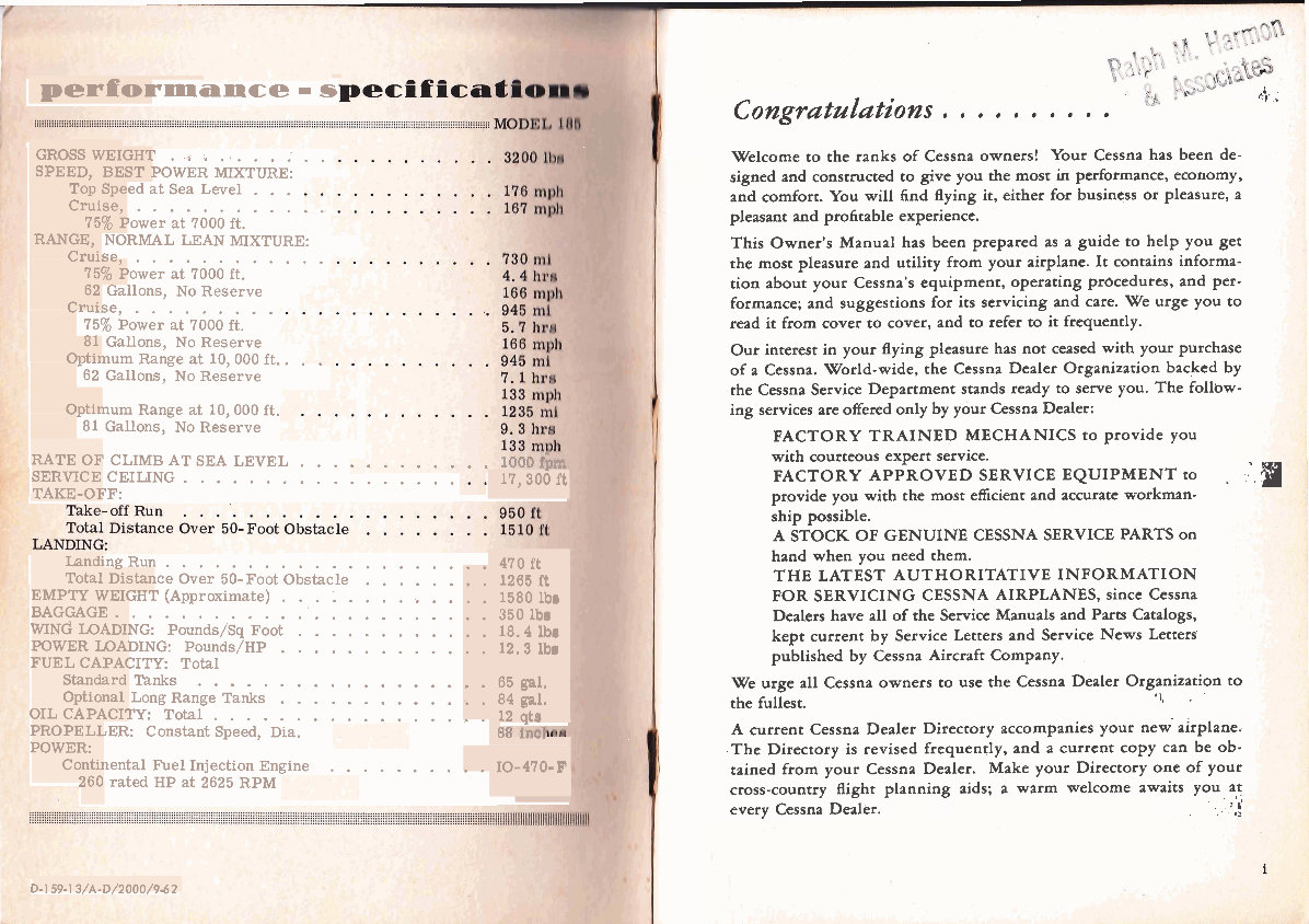
performance - s
.. . ...... GROSS WEIGHT .* .'
SPEED, BEST POWER MIXTURE:
Top Speed at Sea Level ...
Cruise, ............
75% Power at 7000 ft.
RANGE, NORMAL LEAN MIXTURE:
Cruise, ............
75% Power at 7000 ft.
62 Gallons, No Reserve
Cruise, .........
75% Power at 7000 ft.
81 Gallons, No Reserve
..
Optimum Range at 10,000 ft..
62 Gallons, No Reserve
Optimum Range at 10,000 ft.
81 Gallons, No Reserve
RATE OF CLIMB AT SEA LEVEL ...
SERVICE CEILJNG ................. , 17,300 it
TAKE-OFF:
Landing Run .................... 470 ft
Total Distance Over 50-Foot Obstacle ........ 1265 ft
EMPTY WEIGHT (Approximate) ............. 1580 lbr
BAGGAGE ........................ 350 1bm
WING LOADING: ~ o u n d s / ~ q Foot ............ 18.4 lbr
POWER LOADING: Pounds/HP ............. 12.3 lbr
FUEL CAPACITY: Total
Standard Tanks 65 gal.
..................
Optional Long Range Tanks ............. 84 gal,
OIL CAPACITY: Total ................. 12 qtm
PROPELLER: Constant Speed, Dia.
POWER:
Continental Fuel Injection Engine .......... 10-470- F
260 rated HP at 2625 RPM
D-159-13/A-D/2000/942
4.
Congratulations. .........
Welcome to the ranks of Cessna owners! Your Cessna has been de-
signed and constructed to give you the most in performance, economy,
and comfort. You will find flying it, either for business or pleasure, a
pleasant and profitable experience.
This Owner's Manual has been prepared as a guide to help you get
the most pleasure and utility from your airplane. It contains informa-
tion about your Cessna's equipment, operating procedures, and per-
formance; and suggestions for its servicing and care. We urge you to
read it from cover to cover, and to refer to it frequently.
Our interest in your flying pleasure has not ceased with your purchase
of a Cessna. World-wide, the Cessna Dealer Organization backed by
the Cessna Service Department stands ready to serve you. The follbw-
ing services are offered only by your Cessna Dealer:
FACTORY TRAINED MECHANICS to provide you
with courteous expert service.
FACTORY APPROVED SERVICE EQUIPMENT to . .
a
provide you with the most efficient and accurate workman-
ship possible.
A STOCK OF GENUINE CESSNA SERVICE PARTS on
hand when you need them.
THE LATEST AUTHORITATIVE INFORMATION
FOR SERVICING CESSNA AIRPLANES, since Cessna
Dealers have all of the Service Manuals and Parts Catalogs,
kept current by Service Letters and Service News Letters
published by Cessna Aircraft Company.
We urge all Cessna owners to use the Cessna Dealer Organization to
the fullest. 'I, .
A current Cessna Dealer Directory accompanies your new airplane.
.The Directory is revised frequently, and a current copy can be ob-
tained from your Cessna Dealer. Make your Directory one of your
cross-country flight planning aids; a warm welcome awaits you at
every Cessna Dealer.
www.powersportsupply.co
XAELE of CONTENXS
. . . . . . . . . . .... I ........ I.. . . ... . . .. . . . .. . . . . . , , . , , . . . , , , . . . , . . , . , . . , , . . . .. . . . . . . . . . . . . .. . . . . . . . . . . . . . .. . . ... . . . . .. . . . . . . . .. . . . .. . . .. . . . . . . . . . . . . . . . , . . . . . . . . . . . . . . ,, . . . . ,... . ... . . ... . . . .. . . . . ...
..................................................................................................................................................................................................
. ... . . ... . .
::::::: i:iii:iiit:iii Page iiiiiiiijii
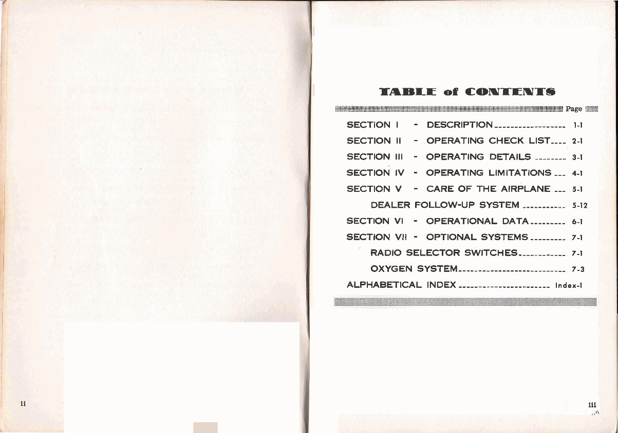
SECTION I - DESCRIPTION ------------------ 1-1
SECTION II - OPERATING CHECK LIST---- 2-1
SECTION Ill - OPERATING DETAILS -------- 3-1
SECTION IV - OPERATING LIMITATIONS --- 4-1
SECTION V - CARE OF THE AIRPLANE --- 5-1
DEALER FOLLOW-UP SYSTEM --,-,,,,--- 5-1 2
SECTION VI - OPERATIONAL DATA ,,,,----- 6-1
SECTION VII - OPTIONAL SYSTEMS ------,-- 7-1
RADIO SELECTOR SWITCHES ----------,, 7-1
OXYGEN SYSTEM -------------- - ------------ 7-3
ALPHABETICAL INDEX ....................... Index-1
iii
.,I\,
www.powersportsupply.co
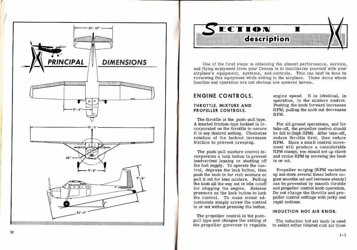
I
DIMENSIONS
One of the first steps in obtaining the utmost performance, service,
and flying enjoyment from your Cessna is to familiarize yourself with your
airplane's equipment, systems, and controls. This can best be done by
reviewing this equipment while sitting in the airplane. Those items whose
function and operation are not obvious are covered herein.
ENGINE CONTROLS. engine speed. ~t is identical, in
operation, to the mixture control.
THROTTLE, MIXTURE AND Pushing the knob forward increases
PROPELLER CONTROLS. RPM, pulling the knob out decreases
RPM.
The throttle is the push-pull type.
A knurled friction-type locknut is in-
corporated on the throttle to secure
it in any desired setting. Clockwise
rotation of the locknut increases
friction to prevent creeping.
The push-pull mixture control in-
corporates a lock button to prevent
inadvertent leaning or shutting off
the fuel supply. To operate the con-
trol, depress the lock button, then
push the knob in for rich mixture or
pull it out for lean mixture. Pulling
the knob all the way out is idle cutoff
for stopping the engine. Release
pressure on the lock button to lock
the control. To make minor ad-
justments simply screw the control
in or out without pressing the button.
The propeller control is the push-
pull type and changes the setting of
the propeller governor to regulate
For all ground operations, and for
take-off, the propeller control should
be full in (high RPM). After take-off,
reduce throttle first, then reduce
RPM. Since a small control move-
ment will produce a considerable
RPM change, you should set up climb
and cruise RPM by screwing the knob
in or out.
Propeller surging (RPM variation
up and down several times before en-
gine smooths out and becomes steady)
can be prevented by smooth throttle
and propeller control knob operation.
Do not change the throttle and pro-
peller control settings with jerky and
rapid motions.
INDUCTION HOT AIR KNOB.
The induction hot air knob is used
to select either filtered cold air from
www.powersportsupply.co
' 1 Description
!
the induction air scoop or heated air
from the accessory compartment. In
the unlikely event that ice should
form in the induction system, as
evidenced by an unexplained drop in
manifold pressure, pull the induc-
tion hot air knob full out. Do not use
an intermediate position.
IGNITION-STARTER SWITCH.
A five-position ignition-starter
switch controls the dual magneto
ignition and starter systems. The
switch positions are labeled clock-
wise as follows: "OFF, " "R, " "L, "
"BOTH" and "START. "
The engine should be operated on
both magnetos ("BOTH" position).
The "R" and " L" positions are for
checking purposes only. When the
switch is turned to the spring-loaded
"START' position, the starter turns
over the engine for starting. As the
switch is released, it automatically
returns to "BOTH. "
b
Refer to Sections I1 and 111 for
further discussion on the use of the
ignition-starter switch.
ENGINE INSTRUMENTS.
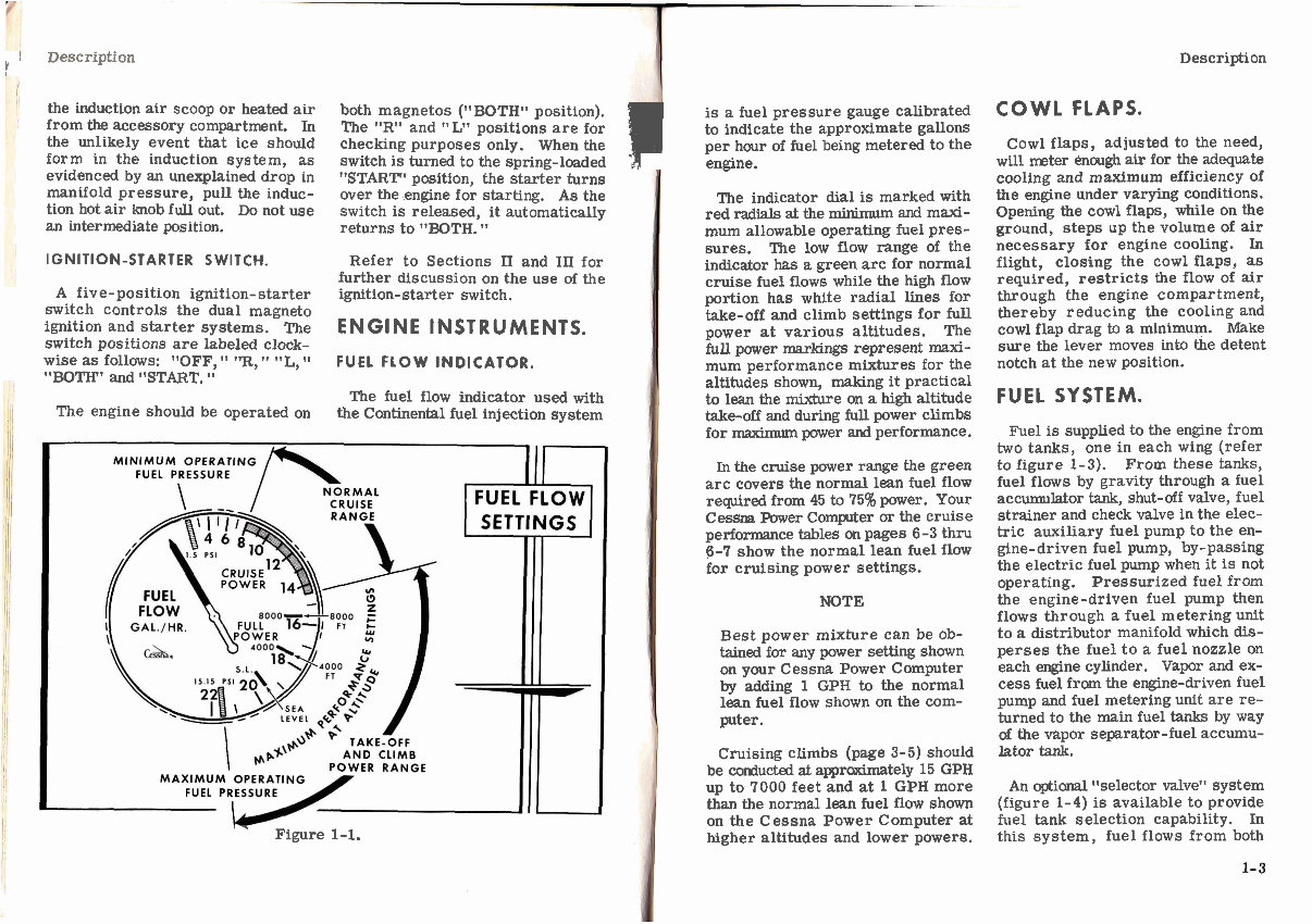
FUEL FLOW INDICATOR.
The fuel flow indicator used with
the Continental fuel injection system
IT
Figure 1-1.
is a fuel pressure gauge calibrated
to indicate the approximate gallons
per hour of fuel being metered to the
engine.
The indicator dial is marked with
red radials at the minimum and maxi-
mum allowable operating fuel pres-
sures. The low flow range of the
indicator has a green arc for normal
cruise fuel flows while the high flow
portion has white radial lines for
take-off and climb settings for full
power at various altitudes. The
full power markings represent maxi-
mum performance mixtures for the
altitudes shown, making it practical
to lean the mixture on a high altitude
take-off and during full power climbs
for maximum power and performance.
In the cruise power range the green
arc covers the normal lean fuel flow
required from 45 to 75% power. Your
Cessna Power Complter or the cruise
performance tables on pages 6-3 thru
6-7 show the normal lean fuel flow
for cruising power settings.
NOTE
Best power mixture can be ob-
tained for any power setting shown
on your Cessna Power Computer
by adding 1 GPH to the normal
lean fuel flow shown on the com-
puter.
Cruising climbs (page 3-5) should
be conducted at apprcximately 15 GPH
up to 7000 feet and at 1 GPH more
than the normal lean fuel flow shown
on the Cessna Power Computer at
higher altitudes and lower powers.
Description
COWL FLAPS.
Cowl flaps, adjusted to the need,
will mter enough air for the adequate
cooling and maximum efficiency of
the engine under varying conditions.
Opening the cowl flaps, while on the
ground, steps up the volume of air
necessary for engine cooling. In
flight, closing the cowl flaps, as
required, restricts the flow of air
through the engine compartment,
thereby reducing the cooling and
cowl flap drag to a minimum. Make
sure the lever moves into the detent
notch at the new position.
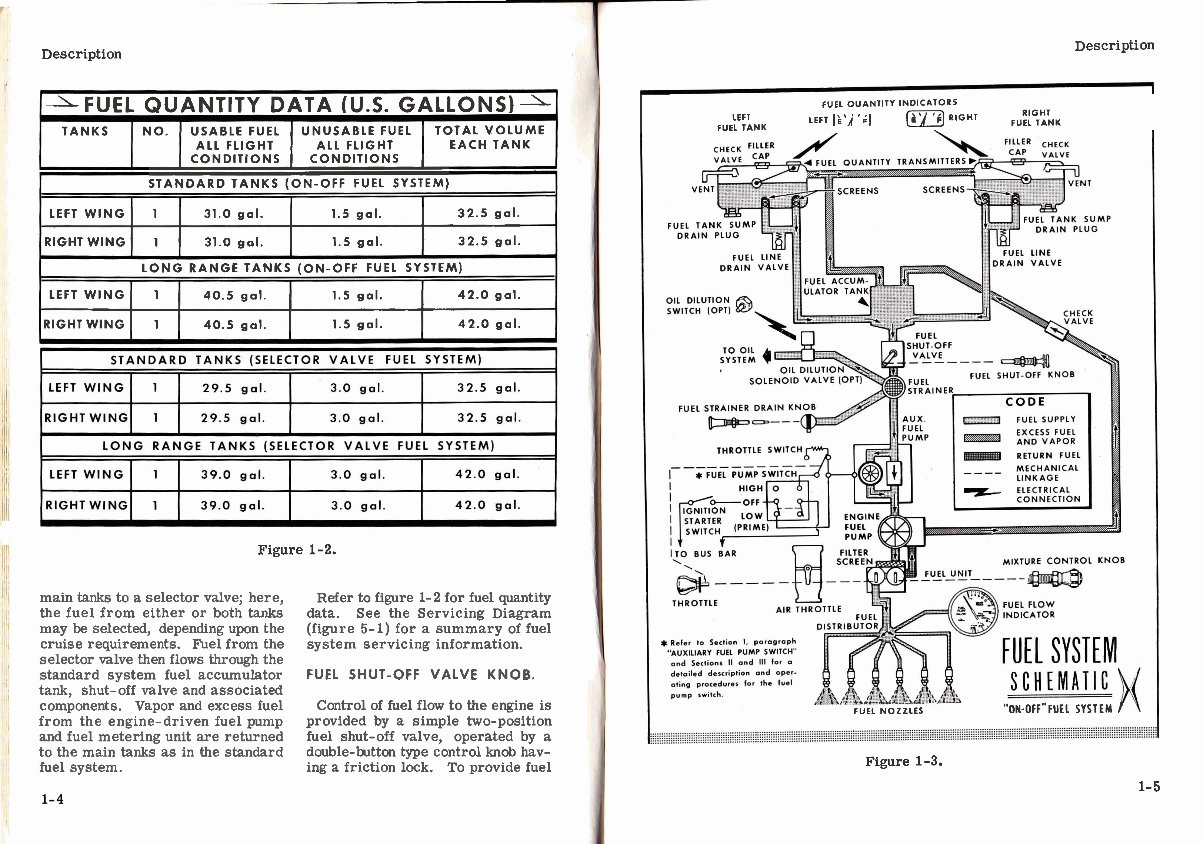
FUEL SYSTEM.
Fuel is supplied to the engine from
two tanks, one in each wing (refer
to figure 1-3). From these tanks,
fuel flows by gravity through a fuel
accumulator tank, shut-off valve, fuel
strainer and check valve in the elec-
tric auxiliary fuel pump to the en-
gine-driven fuel pump, by-passing
the electric fuel pump when it is not
operating. Pressurized fuel from
the engine-driven fuel pump then
flows through a fuel metering unit
to a distributor manifold which dis-
perses the fuel to a fuel nozzle on
each engine cylinder. Vapor and ex-
cess fuel from the engine-driven fuel
pump and fuel metering unit are re-
turned to the main fuel tanks by way
of the vapor separator-fuel accumu-
liltor tank.
An optional "selector valve" system
(figure 1-4) is available to provide
fuel tank selection capability. In
this system, fuel flows from both
www.powersportsupply.co
Description
-FUEL QUANTITY DATA (U.S. GALLONS)-1
TANKS NO. USABLE FUEL UNUSABLE FUEL TOTAL VOLUME
ALL FLIGHT ALL FLIGHT EACH TANK
CONDITIONS CONDITIONS
STANDARD TANKS (ON-OFF FUEL SYSTEM)
LEFT W I N G 1 31.0 gal. 1.5 gal. 32.5 gal.
RIGHT WING 1 31.0 gal. 1.5 gal. 32.5 gal.
LONG RANGE TANKS (ON-OFF FUEL SYSTEM)
LEFT WING 1 40.5 gal. 1.5 gal. 42.0 gal.
RIGHTWING 1 40.5 gal. 1.5 gal. 42.0 gal.
Figure 1-2.
main tanks to a selector valve; here,
the fuel from either or both tanks
may be selected, depending upon the
cruise requirements. Fuel from the
selector valve then flows through the
standard system fuel accumulator
tank, shut-off valve and associated
components. Vapor and excess fuel
from the engine-driven fuel pump
and fuel metering unit are returned
to the main tanks as in the standard
fuel system.
Refer to figure 1- 2 for fuel quantity
data. See the Servicing Diagram
(figure 5-1) for a summary of fuel
system servicing information.
FUEL SHUT-OFF VALVE KNOB.
Control of fuel flow to the engine is
provided by a simple two-position
fuel shut-off valve, operated by a
double-button type control knob hav-
ing a friction lock. To provide fuel
Description
r LEFT
FUEL TANK
FUEL OUANTITY INDICATORS
RIGHT
EFT RIGHT FUEL T A ~ ~
.
FUEL NOZZLES "ON-OFF"FUEL SYSTEM I
Figure 1-3.
1-5
www.powersportsupply.co
Description
flow, squeeze the control knob but-
tons together, releasing the lock, and
push the knob full in. Fuel will flow
from both wing fuel tanks simultan-
eously.
NOTE
With full fuel, the tanks may not
drain evenly because fuel may be
sloshed into the interconnect vent
line, preventing absolutely equal
vent pressures in each tank. How-
ever, as fuel is consumed, clear-
ing the interconnect vent line and
equalizing tank vent pressures, the
fuel quantities should equalize in
each tank.
When the control knob is pulled full
out, the shut-off valve is closed,
sealing off the wing tanks and fuel
accumulator tank from the engine.
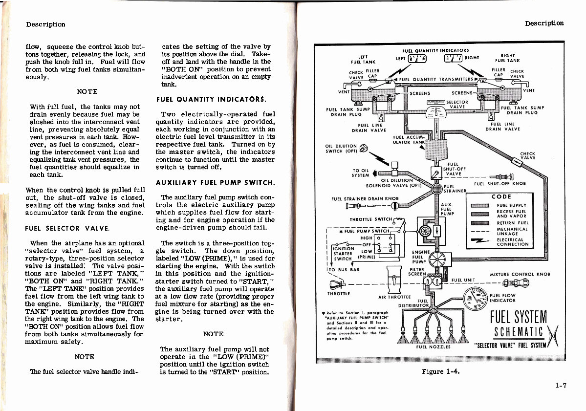
FUEL SELECTOR VALVE.
When the airplane has an optional
"selector valve" fuel system, a
rotary-type, three-position selector
valve is installed; The valve posi-
tions are labeled "LEFT TANK,"
"BOTH ON" and "RIGHT TANK."
The "LEFT TANK' position provides
fuel flow from the left wing tank to
the engine. Similarly, the "RIGHT
TANK' position provides flow from
the right wing tank to the engine. The
"BOTH ON" position allows fuel flow
from both tanks simultaneously for
maximum safety .
NOTE
The fuel selector valve handle indi-
cates the setting of the valve by
its pasition above the dial. Take-
off and land with the handle in the
"BOTH OW1 position to prevent
inadvertent operation on an empty
tank.
FUEL QUANTITY INDICATORS.
Two electrically-operated fuel
quantity indicators are provided,
each working in conjunction with an
electric fuel level transmitter in its
respective fuel tank. Turned on by
the master switch, the indicators
continue to function until the master
switch is turned off.
AUXILIARY FUEL PUMP SWITCH.
The auxiliary fuel pump switch con-
trols the electric auxiliary pump
which supplies fuel flow for start-
ing and for engine operation if the
engine-driven pump should fail.
The switch is a three-position tog-
gle switch. The down position,
labeled "LOW (PRIME), " is used for
starting the engine. With the switch
in this position and the ignition-
starter switch turned to "START, 'I
the auxiliary fuel pump will operate
at a low flow rate (providing proper
fuel mixture for starting) as the en-
gine is being turned over with the
starter.
NOTE
The auxiliary fuel pump will not
operate in the "LOW (PRIME)"
position until the ignition switch
is turned to the "START" position.
Description
FUEL OUANTITY INDICATORS
LEFT LEFT li) RIGHT RIGHT
FUEL TANK FUEL TANK
I
Figure 1-4.
www.powersportsupply.co
Description
The up position of the switch, la-
beled ItHIGH, " is used for engine op-
eration if the engine-driven pump
should fail, or for vapor purging in
extremely hot weather. When the
switch is in this position, the pump
can operate at two f l m rates depend-
ing upon the setting of the throttle.
With the throttle at a cruise setting,
the pump is operating at maximum
capacity, supplying sufficient fuel
flow to maintain flight with the en-
gine-driven pump inoperative. When
the throttle is moved toward the
closed position, as during let-down,
landing and taxiing, a mechanically-
actuated switch electrically reduces
the auxiliary fuel pump flow rate by
means of a resistor in the pump
power circuit. This action auto-
matically prevents an excessively
rich mixture during these periods of
reduced engine speed.
The auxiliary fuel pump is not to
be on "HIGHt7 during normal oper-
ation, because, with the engine-driven
pump functioning, a fuel/air ratio
considerably richer than best power
is produced. If fuel vapor is affect-
ing engine operation, the vapor may
be purged by turning the auxiliary
pump to "HIGH" and leaning the mix-
ture as required to prevent exces-
sively rich mixture. Successful vapor
purging is evidenced by smooth en-
gine operation and steady and normal
fuel flow indications with the auxiliary
fuel pump switch "OFF. It
NOTE
If the auxiliary fuel pump switch is
accidentally turned to "HIGHt (with
master switch on) with the engine
stopped, intake manifolds will be
flooded unless the mixture is in
idle cut-off.
The center position of the auxiliary
fuel pump switch is "OFF. "
FUEL STRAINER DRAIN KNOB.
A fuel strainer drain knob marked
"STRAWER DRAIN' provides a quick,
convenient method of draining water
and sediment that may have collected
in the fuel strainer. The strainer is
located on the lower front side of the
f irewall.
About two ounces of fuel (3 to 4
seconds of drain knob operation)
should be drained from the strainer
before the initial flight of the day to
insure against the presence of water
or sediment in the fuel.
The spring-loaded drain valve in
the strainer is open when the fuel
strainer drain knob is pulled out all
the way. The drain valve automatic-
ally closes when the knob is released.
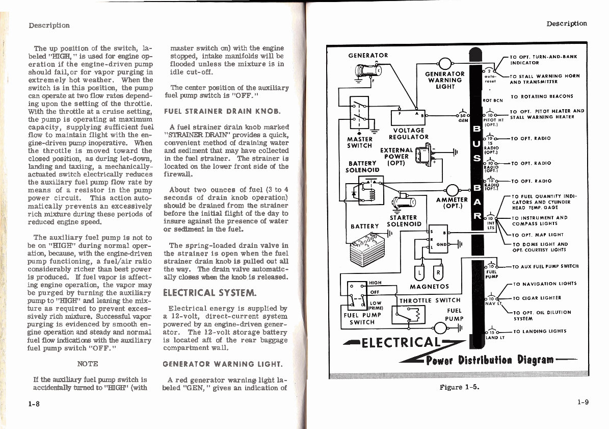
ELECTRICAL SYSTEM.
Electrical energy is supplied by
a 12-volt, direct-current system
powered by an engine-driven gener-
ator. The 12-volt storage battery
is located aft of the rear baggage
compartment wall.
GENERATOR WARNING LIGHT.
A red generator warnine light la-
beled "GEN, " gives an indication of
Description
GENERATOR
TO OPT. TURN-AND-BANK
INDICATOR
TO STALL WARNING HORN
AND TRANSMITTER
LlGHT
oCa
GEN
SWITCH EXTERNAL$ {I,
POWER
BATTERY (OPT)
SOLENOID
I BATTERY SOLENoiD I)-,
TO ROTATING BEACONS
ROT BCN
PITOT HEATER AND
WARNING HEATER
/-To RADIO OPT RADIO
(OPT.)
I&TO RADIO on. RADIO
10PT.l
/*-To OPT. RADIO
RADlO
I0PT.I
TO FUEL QUANTITY INDI-
CATORS AND CYLINDER
HEAD TEMP. GAGE
TO INSTRUMENT AND
COMPASS LIGHTS
TO OPT. MAP LIGHT
TO DOME LIGHT AND
OPT. COURTESY LIGHTS
bF$LLTo
AUX FUEL PUMP SWITCH
PUMP
TO NAVIGATION LIGHTS
TO CIGAR LIGHTER
TO OPT. OIL DILUTION
SYSTEM
TO LANDING LIGHTS
-ELECT? ) LAND LT
Power Distribution Diagram -
Figure 1-5.
www.powersportsupply.co
Description
generator output. It will remain off
at all times when the generator is-
functioning properly. The light will
not show drainage on the battery. It
'
will illuminate when the battery or
external power is turned on prior to
starting the engine, and when there
is insufficient engine RPM to produce
generator current. Also, it will
illuminate if the generator becomes
defective.
CIRCUIT BREAKERS.
All electrical circuits in the air-
plane are protected by circuit break-
ers. The stall warning, generator
warning light, and optional turn-and-
bank indicator circuits are protected
by a single automatically resetting
circuit breaker mounted behind the
instrument panel. The remaining
electrical circuits are protected by
"push-to-resetM breakers on the in-
strum ent panel. The name of the
circuit is indicated above each cir-
cuit breaker.
LANDING LIGHTS.
The landing light switch is a three-
position, push-pull switch. To turn
one lamp on for taxiing, pull the
switch out to the first stop. To turn
both lamps on for landing, pull the
switch out to the second stop.
ROTATING BEACONS.
The beacons should not be used
when flying through clouds o r over-
cast; the m oving beams reflected
from water droplets or particles in
the atmosphere, particularly at night,
can produce vertigo and loss of ori-
entation.
STALL WARNING INDICATOR
The stall warning indicator is an
electric horn controlled by a trans-
mitter unit in the leading edge of the
left wing. This system is in oper-
ation whenever the master switch
is turned on. The transmitter re-
sponds to changes in the airflow over
the leading edge of the wing as a stall
is approached. In straight-ahead
and turning flight, the warning horn
will sound 5 to 10 MPH ahead of the
stall.
Under safe flight conditions, the
only time you may hear the warning
horn will be a short beep a s you land.
CABIN HEATING AND
VENTILATION SYSTEM.
Fresh air for heating and venti-
lating the cabin is supplied by two
sources, a manifold cabin heater and
a ventilating air scoop on the right
side of the fuselage.
The temperature and amount of air
entering the cabin is controlled by
two knobs on the instrument panel.
The "CABIN AIR" knob operates the
air scoop on the right side of the
fuselage and controls cool fresh air
entering the manifold on the firewall.
The "CABIN HT' knob regulates the
amount of heat entering the cabin.
The "CABIN HT" knob is the double-
button type with a friction lock to
permit intermediate settings. To
operate the knob, squeeze the buttons
together, releasing the lock, then
adjust the knob.
For cabin ventilation, pull the
"CABIN AIRf7 knob out. To raise
the air temperature, pull the "CABIN
HT1 knob out approximately 1/4" to
1/2" for a small am& of cabin heat.
Adjust the knob as desired from this
position to the full out (maximum
heat) position.
NOTE
Always pull out the "CABIN AIR"
knob slightly when the "CABIN
HT" knob is out. This action in-
creases the airflow through the
system, increasing efficiency,
and blends cool outside air with
the manifold heated air, thus
eliminating the possibility of
overheating the system ducting.
When no heat is desired in the cabin,
push the "CABIN HT" knob full in.
Description
VENTILATORS.
Two ventilators, one in each upper
corner of the windshield, are provided
to supply additional ventilating air.
To operate, pull the ventilator out
and rotate to the desired position.
Two additional ball and socket venti-
lators are installed just forward of
each rear door post in the ceiling,
for rear seatpassengers. To regu-
late the air, turn the knurled ring on
the rim of the ventilator.
REMOVABLE CABIN DOOR.
The right cabin door has removable
hinge pins and a detachable door stop
permitting door removal when large
or bulky cargo must be loaded. To
disconnect the door stop, simply re-
move the cotter pin and clevis pin
from the door stop rod at the door
frame. To remove the hinge pins,
pull them up and out of the hinges.
Support the door as the pins are re-
moved.
www.powersportsupply.co
32~
i
0
.
r( 4
a OP I
9 2-
+I
m
oa%
5
u YZl
E Z ~
.-P d
T$
a+
' d m .g k IC
.. -
I w
is
9
I
5
3
*
'PI 8
sad "Q~Z
lE 0"
z I G ~
Ikth
a22 2
5x9;.
4~81
hhhh
FIN*)*
VYWV
www.powersportsupply.co
You're Reading a Preview
What's Included?
Fast Download Speeds
Online & Offline Access
Access PDF Contents & Bookmarks
Full Search Facility
Print one or all pages of your manual
$35.99
$46.99
Viewed 19 Times Today


Secure transaction
What's Included?
Fast Download Speeds
Online & Offline Access
Access PDF Contents & Bookmarks
Full Search Facility
Print one or all pages of your manual
$35.99
$46.99
The Cessna 185 Skywagon 1963 185B owner's manual is a comprehensive guide for maintaining and repairing the aircraft. It contains essential technical information relevant to the Cessna 185B model, making it valuable for both professional mechanics and DIY enthusiasts.


