

Cessna 172RWD Wiring Diagram Manual Model 172R 172S
What's Included?
Fast Download Speeds
Online & Offline Access
Access PDF Contents & Bookmarks
Full Search Facility
Print one or all pages of your manual
cess
Teto ompany
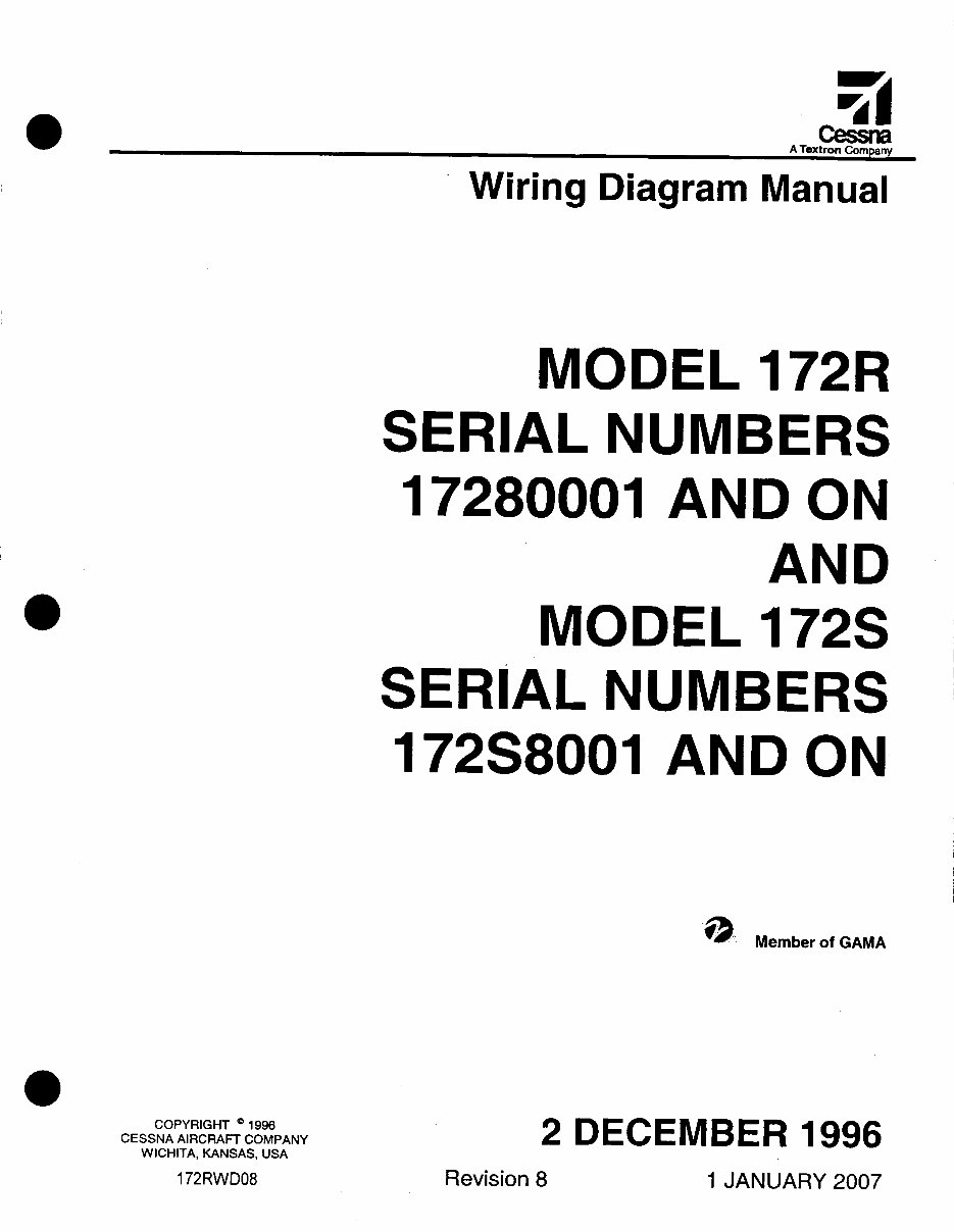
Wiring Diagram Manual
MODEL
172R
SERIAL
NUMBERS
17280001
AND ON
AND
MODEL
172S
SERIAL
NUMBERS
172S8001
AND ON
1) Member of GAMA
COPYRIGHT 1996
CESSNA AIRCRAFT COMPANY
2 DECEMBER 1996
WICHITA, KANSAS, USA
172RWD08
Revision 8
1 JANUARY 2007
CESSNA AIRCRAFT COMPANY
MODEL 172
WIRING DIAGRAM MANUAL
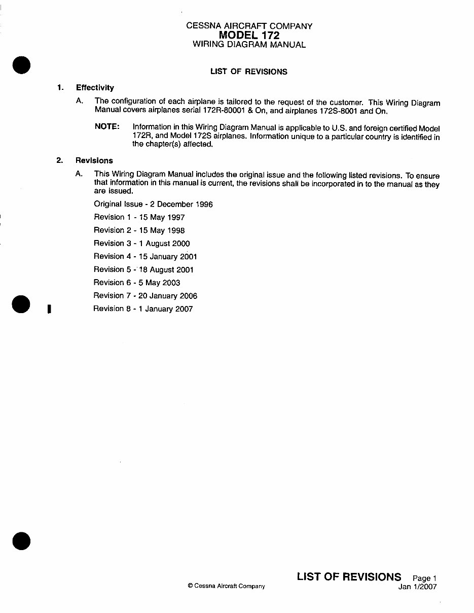
LIST OF REVISIONS
1. Effectivity
A. The configuration of each airplane is tailored to the request of the customer. This Wiring Diagram
Manual covers airplanes serial 1721R-80001 & On, and airplanes 172S-8001 and On.
NOTE: Information in this Wiring Diagram Manual is applicable to U.S. and foreign certified Model
1 72R, and Model 172S airplanes. Information unique to a particular country is identified in
the chapter(s) affected.
2. Revisions
A. This Wiring Diagram Manual includes the original issue and the following listed revisions. To ensure
that information in this manual is current, the revisions shall be incorporated in to the manual as they
are issued.
Original Issue - 2 December 1996
Revision 1 - 15 May 1997
Revision 2 - 15 May 1998
Revision 3 - 1 August 2000
Revision 4 - 15 January 2001
Revision 5 -'18 August 2001
Revision 6 - 5 May 2003
Revision 7 - 20 January 2006
Revision 8 - 1 January 2007
Q Cessna Aircraft Company
LIST OF REVISIONS Page 1
Janl1/2007
I
CESSNA AIRCRAFT COMPANY
MODEL 172
WIRING DIAGRAM MANUAL
CHAPTER
SECTION
SUBJECT
Title
List of Revisions
Introduction-List of Effective Pages
Introduction
Zone Numbering System
Light Bulb Replacement Guide
Fuse Replacement Guide
Service Bulletin List
Engineering Approved Abbreviations
Vendor Address List
Vendor Publications
List of Chapters
Alphabetical Index
Component Index
Reference Designator Index
Part Number Index
NUMBER
OF
PAGES DATE
1 Janl1/2007
1 Janl1/2007
1 Janl1/2007
12 Jan 20/2006
3 Jan 20/2006
2 Jan 20/2006
1 Jan 20/2006
6 Jan 20/2006
1 Jan 20/2006
3 Jan 20/2006
1 Jan 20/2006
1 Janl1/2007
5 Janl1/2007
15 Janl1/2007
40 Janl1/2007
22 Janl1/2007
INTRODUCTION - EFFECTIVITIES
© Cessna Aircraft Company
Page 1
Janl1/2007
CESSNA AIRCRAFT COMPANY
MODEL 172
WIRING DIAGRAM MANUAL
INTRODUCTION
1. Coverage
A. The Wiring Diagram Manual is prepared in accordance with Air Transport Association (ATA)
Specification 100 for Manufacturer's Technical Data.
B. The information in this publication is based on data available at the time of publication and is
updated, supplemented, and automatically amended by all information issued in Service News
Letters, Service Bulletins, Supplier Service Notices, Publication Changes, Revisions, Reissues
and Temporary Revisions. All such amendments become part of and are specifically incorporated
within this publication. Users are urged to keep abreast of the latest amendments to this publication
through information available at Cessna Authorized Service Stations or through the Cessna Product
Support subscription services. Cessna Service Stations have supplier publications which provide
disassembly, overhaul, and parts breakdowns for some of the various supplier equipment items.
Suppliers publications are updated, supplemented, and specifically amended by supplier issued
revisions and service information which may be reissued by Cessna, thereby automatically amending
this publication and are communicated to the field through Cessna's Authorized Service Stations
and/or through Cessna's subscription services.
WARNING: ALL INSPECTION INTERVALS, REPLACEMENT TIME LIMITS,
OVERHAUL TIME LIMITS, THE METHOD OF INSPECTION, LIFE
LIMITS, CYCLE LIMITS, ETC., RECOMMENDED BY CESSNA ARE
SOLELY BASED ON THE USE OF NEW, REMANUFACTURED,
OR OVERHAULED CESSNA APPROVED PARTS. IF PARTS
ARE DESIGNED, MANUFACTURED, REMANUFACTURED,
OVERHAULED, AND/OR APPROVED BY ENTITIES OTHER
THAN CESSNA, THEN THE DATA IN CESSNA'S MAINTENANCE/
SERVICE MANUALS AND PARTS CATALOGS ARE NO LONGER
APPLICABLE AND THE PURCHASER IS WARNED NOT TO RELY
ON SUCH DATA FOR NON-CESSNA PARTS. ALL INSPECTION
INTERVALS, REPLACEMENT TIME LIMITS, OVERHAUL TIME
LIMITS, THE METHOD OF INSPECTION, LIFE LIMITS, CYCLE
LIMITS, ETC., FOR SUCH NON-CESSNA PARTS MUST BE
OBTAINED FROM THE MANUFACTURER AND/OR SELLER OF
SUCH NON-CESSNA PARTS.
C. Inspection, maintenance and parts requirements for Supplemental Type Certification (STC)
installations are not included in this manual. When an STC installation is incorporated on the
airplane, those portions of the airplane affected by the installation must be inspected in accordance
with the inspection program published by the owner of the STC. Since STC installations may change
systems interface, operating characteristics and component loads or stresses on adjacent structures.
Cessna provided inspection criteria may not be valid for airplanes with STC installations.
D. This manual has been prepared to assist personnel in maintaining wiring and electricaVelectronic
components in this airplane and provides the necessary information required to troubleshoot, remove
and replace components or repair systems.
E. Information beyond the scope of this manual may be found in the Maintenance Manual, Illustrated
Parts Catalog and Structural Repair Manual. For technical assistance concerning this manual, contact
Cessna Aircraft Company, Propeller Aircraft Product Support.
F. Technical Publications available from suppliers of various components and systems, which are not
covered in this manual, must be utilized as required for maintenance of those components.
INTRODUCTION Page 1
© Cessna Aircraft Company Jan 20/2006
A
I
CESSNA AIRCRAFT COMPANY
MODEL 172
WIRING DIAGRAM MANUAL
G. Publications for this model are available in paper, aerofiche and CD-ROM versions. For information
concerning the different versions and availability of these publications, contact Cessna Aircraft
Company, Propeller Aircraft Product Support.
(1) Paper versions are available as individual publications.
(2) Aerofiche versions are available as individual publications. Aerofiche versions are a copy of the
paper version of the manual.
(3) Maintenance Manual, Illustrated Parts Catalog, Wiring Diagram Manual and Structural Repair
Manual CD-ROM versions are grouped together on a CD-ROM. Refer to the CD-ROM
introduction for information about items marked as (Paper version of this manual only.).
2. Effectivity
A. This Wiring Diagram Manual covers Model 172R, Airplanes 17280001 and On; and Model 172S,
Airplanes 172S08001 and On.
NOTE: Information in this Wiring Diagram Manual is applicable to U.S. and foreign certified Model
172R, Airplanes 17280001 and On; and Model 172S, Airplanes 172S08001 and On.
Information unique to a particular country is identified in the chapter(s) affected.
3. List of Effective Pages(Paper version of this manual only.)
A. A list of effective pages is provided with each wiring diagram manual chapter. All pages in the chapter
are listed in sequence with the most recent revision date for each page.
4. Temporary Revision(Paper version of this manual only.)
A. Additional information which becomes available will be provided through temporary revision. This
service is used to provide, without delay, new information which will assist in maintaining safe and
efficient flight/ground operations. The temporary revisions are normally incorporated in the wiring
diagram manual at the next revision, and then becomes a permanent part of the manual.
5. Revision Filing Instructions
A. Regular Revision.
(Paper version of this manual only.)
(1) Refer to the List of Effective pages of each chapter while inserting a revision.
(2) Pages changed by the revision will be indicated by the revision date on the page and on the List
of Effective pages for that chapter. The revised page replaces the existing page in the manual.
(3) New pages added to the manual are indicated by "Added" on the List of Effective pages. Pages
are inserted in the manual in sequence by chapter/section/subject and page number.
(4) Existing pages no longer needed in the manual are indicated by "Deleted" on the List of Effective
pages. These pages are to be removed and discarded. When a page has been deleted by a
revision, the List of Effective pages for subsequent revisions does not list the page.
B. Temporary Revisions:
(Paper version of this manual only.)
(1) File temporary revisions in the applicable chapter in accordance with filing instructions that
appear on the title page.
(2) Temporary revisions should be removed from the manual only when replaced by a revision to
the manual or by instructions noted on the superseding temporary revision.
6. Revision Indicators
A. Additions, deletions or revisions to text in an existing section will be identified by a revision bar in the
left margin of the page adjacent to the change. This is applicable to the List of Revisions, Introduction,
Chapter 20, and Chapter 91 only.
B. When technical changes cause unchanged text to appear on a different page/pages, a revision bar
will be placed in the margin opposite the page number of all affected pages. These pages will be
updated to the current revision date.
INTRODUCTION Page 2
© Cessna Aircraft Company Jan 20/2006
CESSNA AIRCRAFT COMPANY
MODEL 172
WIRING DIAGRAM MANUAL
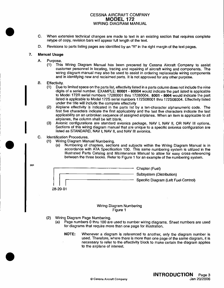
C. When extensive technical changes are made to text in an existing section that requires complete
retype of copy, revision bars will appear full length of the text.
D. Revisions to parts listing pages are identified by an "R" in the right margin of the text pages.
7. Manual Usage
A. Purpose.
(1) This Wiring Diagram Manual has been prepared by Cessna Aircraft Company to assist
customer personnel in locating, tracing and repairing of aircraft wiring and components. The
wiring diagram manual may also be used to assist in ordering replaceable wiring components
and in identifying new and reclaimed parts. It is not approved for any other purpose.
B. Effectivity.
(1) Due to limited space on the parts list, effectivity listed in a parts column does not include the nine
digits of a serial number. EXAMPLE: 80001 - 80004 would indicate the part listed is applicable
to Model 172R serial numbers 17280001 thru 17280004. 8001 - 8004 would indicate the part
listed is applicable to Model 172S serial numbers 172S08001 thru 172S08004. Effectivity listed
under the title will include the complete effectivity
(2) Airplane effectivity is indicated in the parts list by a ten-character alphanumeric code. The
first five characters indicate the first applicability and the last five characters indicate the last
applicability on an unbroken sequence of assigned airplanes. When an item is applicable to all
airplanes, the column shall be left blank.
(3) Avionic configurations are standard avionics package, NAV I, NAV II, OR NAV III options.
Sections of this wiring diagram manual that are unique to a specific avionics configuration are
listed as STANDARD, NAV I, NAV II, and NAV III avionics.
C. Identification Procedures.
(1) Wiring Diagram Manual Numbering.
(a) Numbering of chapters, sections and subjects within the Wiring Diagram Manual is in
accordance with ATA Specification 100. This same numbering system is utilized in the
Illustrated Parts Catalog and Maintenance Manual to allow for easy cross-referencing
between the three books. Refer to Figure 1 for an example of the numbering system.
861
Chapter (Fuel)
Subsystem (Distribution)
i Specific Diagram (Left Fuel Control)
28-20-01
Wiring Diagram Numbering
Figure 1
(2) Wiring Diagram Page Numbering.
(a) Page numbers 0 thru 100 are used to number wiring diagrams. Sheet numbers are used
for diagrams that require more than one page for illustration.
NOTE: Whenever a diagram is referenced to another, only the diagram number is
used. Therefore, where there is more than one page of the same diagram, it is
necessary to refer to the effectivity block to make certain the diagram applies
to the airplane of interest.
INTRODUCTION Page 3
© Cessna Aircraft CompanY Jan 20/2006
CESSNA AIRCRAFT COMPANY
MODEL 172
WIRING DIAGRAM MANUAL
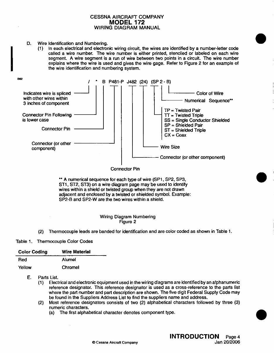
D. Wire Identification and Numbering.
(1) In each electrical and electronic wiring circuit, the wires are identified by a number-letter code
called a wire number. The wire number is either printed, stenciled or labeled on each wire
segment. A wire segment is a run of wire between two points in a circuit. The wire number
explains where the wire is used and gives the wire gage. Refer to Figure 2 for an example of
the wire identification and numbering system.
/ * B P481-P
Indicates wire is spliced
with other wires within
3 inches of component
Connector Pin Following
is lower case
Connector Pin
Connector (or other
component)
J482 (24) (SP 2- B)
l- I
Color of Wire
Numerical Sequence"
TP = Twisted Pair
- TT = Twisted Triple
SS = Single Conductor Shielded
SP = Shielded Pair
ST = Shielded Triple
CX = Coax
Wire Size
Connector (or other component)
Connector Pin
** A numerical sequence for each type of wire (SP1, SP2, SP3,
ST1, ST2, ST3) on a wire diagram page may be used to identify
wires within a shield or twisted group when they are not drawn
adjacent and enclosed by a twisted or shielded symbol. Example:
SP2-B and SP2-W are the two wires within a shield.
Wiring Diagram Numbering
Figure 2
(2) Thermocouple leads are banded for identification and are color coded as shown in Table 1.
Table 1. Thermocouple Color Codes
Color Coding
Red
Yellow
Wire Material
Alumel
Chromel
E. Parts List.
(1) Electrical and electronic equipment used in the wiring diagrams are identified by an alphanumeric
reference designator. This reference designator is used as a cross-reference to the parts list
where the part number and part description are shown. The five digit Federal Supply Code may
be found in the Suppliers Address List to find the suppliers name and address.
(2) Most reference designators consists of two (2) alphabetical characters followed by three (3)
numeric characters.
(a) The first alphabetical character denotes component type.
O Cessna Aircraft Company
INTRODUCTION Page 4
Jan 20/2006
0
CESSNA AIRCRAFT COMPANY
MODEL 172
WIRING DIAGRAM MANUAL
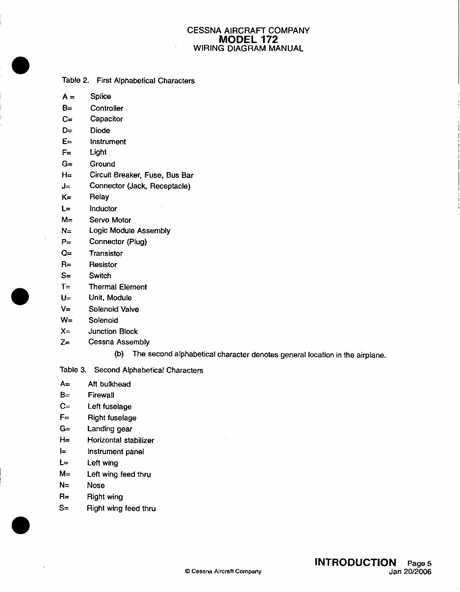
Table 2. First Alphabetical Characters
A = Splice
B= Controller
C= Capacitor
D= Diode
E= Instrument
F= Light
G= Ground
H= Circuit Breaker, Fuse, Bus Bar
J= Connector (Jack, Receptacle)
K= Relay
L= Inductor
M= Servo Motor
N= Logic Module Assembly
P= Connector (Plug)
Q= Transistor
R= Resistor
S= Switch
T= Thermal Element
U= Unit, Module
V= Solenoid Valve
W= Solenoid
X= Junction Block
Z= Cessna Assembly
(b) The second alphabetical character denotes general location in the airplane.
Table 3. Second Alphabetical Characters
A= Aft bulkhead
B= Firewall
C= Left fuselage
F= Right fuselage
G= Landing gear
H= Horizontal stabilizer
I= Instrument panel
L= Left wing
M= Left wing feed thru
N= Nose
R= Right wing
S= Right wing feed thru
INTRODUCTION Page 5
© Cessna Aircraft Company Jan 20/2006
CESSNA AIRCRAFT COMPANY
MODEL 172
WIRING DIAGRAM MANUAL
Table 3. Second Alphabetical Characters (continued)
T= Tailcone
V= Vertical stabilizer
Z= Inside a Cessna Assembly
(c) The three (3) numeric characters are sequentially assigned and do not denote location or
order of occurrence.
F. List of Chapters.
(Paper version of this manual only.)
(1) The List of Chapters includes all chapters used in this manual.
G. Alphabetical Indexes.
(Paper version of this manual only.)
(1) The Alphabetical Index lists all subjects in this manual.
(2) The Component Index is an alphabetical list of components in this manual.
H. Reference Designator Index
(Paper version of this manual only.)
(1) The Reference Designator Index is a complete listing of all reference designators included in
the parts list. All reference designators are cross-referenced to the part number and applicable
chapter, section, subject and figure where the reference designator is used.
I. Part Number Indexes.
(Paper version of this manual only.)
(1) The Part Number Index is a complete listing of all parts included in the parts list. All part numbers
are cross-referenced to the reference designator and applicable chapter, section, subject and
figure where the part number is used.
J. Chapter 20 Includes.
(1) Safety precautions.
(2) General maintenance information for wire repairs, grounding of wires, soldering, heat shrink
tubing, resistors, torque values, connectors, and relay sockets.
(3) Information on connectors for removal and installation of contacts, contact pin and socket part
numbers, tools to crimp the contacts, sealing of potted type connectors and connector contact
arrangements.
K. Chapter 91 Includes.
(1) Reference information for connectors, ground locations and component locations.
(a) Connector charts are provided for those connectors that contain wires for several different
systems. All contact pins are shown for the complete connector. The wire number for each
wire to a pin is shown with reference to the system where the complete circuit will be found.
(b) Ground locations are provided for all grounds.
(c) Component location charts are provided listing each reference designator and its location
in the airplane.
L. How To Use This Manual.
(1) All operable electrical components, such as relays, etc., are shown with the airplane on the
ground, all circuits off or de-energized and no electrical power on the circuits. Switches are
shown in the off or normal position unless otherwise noted.
(2) The parts list may consist of two or more text lines. Make certain that all lines are observed, as
the part number and part description are not always complete on the first line.
(3) Some wire diagrams have too many parts to list on one page of text. In this case, identical wire
diagrams are used with a different parts list for each diagram.
(4) Letters or numbers are used to identify the contacts of a connector to which each wire is
connected.
(a) The letter or number shown on the wiring diagram is also marked on the connector.
INTRODUCTION Page 6
© Cessna Aircraft Company Jan 20/2006
CESSNA AIRCRAFT COMPANY
MODEL 172
WIRING DIAGRAM MANUAL
(b) A letter that is underlined or preceded by an asterisk indicates a lower case letter. On wire
diagrams, the letter may be printed in either lower case or capital letters, but both indicate
lower case on the connector.
8. Suppliers Addresses and Publications
A. Refer to the Supplier's Address List for suppliers names and addresses.
B. Refer to the Supplier's Publication List for suppliers names and publications.
9. Service Bulletins
A. A record of service bulletins are listed in the Service Bulletin List.
B. The list of service bulletins summarizes the following information:
(1) Service Bulletin Number - Identifies the service bulletin that corresponds to a modification kit.
Service bulletins are numbered consecutively starting with number one.
(2) Service Bulletin Date - The printing date of the service bulletin.
(3) Manual Incorporation Date - Indicates when the service bulletin was incorporated into the
manual.
(a) No Effect - This indicates the service bulletin does not affect the manual.
(b) Other self-explanatory statements may appear (i.e., replaces, replaced, superseded, etc.).
(4) Title - Identifies the service bulletin by nomenclature. It is the same title displayed on page one
of the service bulletin.
10. Engineering Approved Abbreviations
A. A record of engineering approved abbreviations used in this manual are listed in the Engineering
Approved Abbreviations List.
11. Symbols
A. Refer to Figure 3 for examples of symbols used in this wiring diagram manual.
INTRODUCTION Page 7
© Cessna Aircraft Company Jan 20/2006
You're Reading a Preview
What's Included?
Fast Download Speeds
Online & Offline Access
Access PDF Contents & Bookmarks
Full Search Facility
Print one or all pages of your manual
$61.99
Viewed 54 Times Today


Secure transaction
What's Included?
Fast Download Speeds
Online & Offline Access
Access PDF Contents & Bookmarks
Full Search Facility
Print one or all pages of your manual
$61.99
This wiring diagram manual is designed for the MODEL 172R with serial numbers 17280001 and onward, as well as the MODEL 172S with serial numbers 172S8001 and onward. Produced by CESSNA AIRCRAFT COMPANY on 2 December 1996, this manual, with Revision 8 dated 1 January 2007, is an essential resource for both professional mechanics and DIY enthusiasts.


