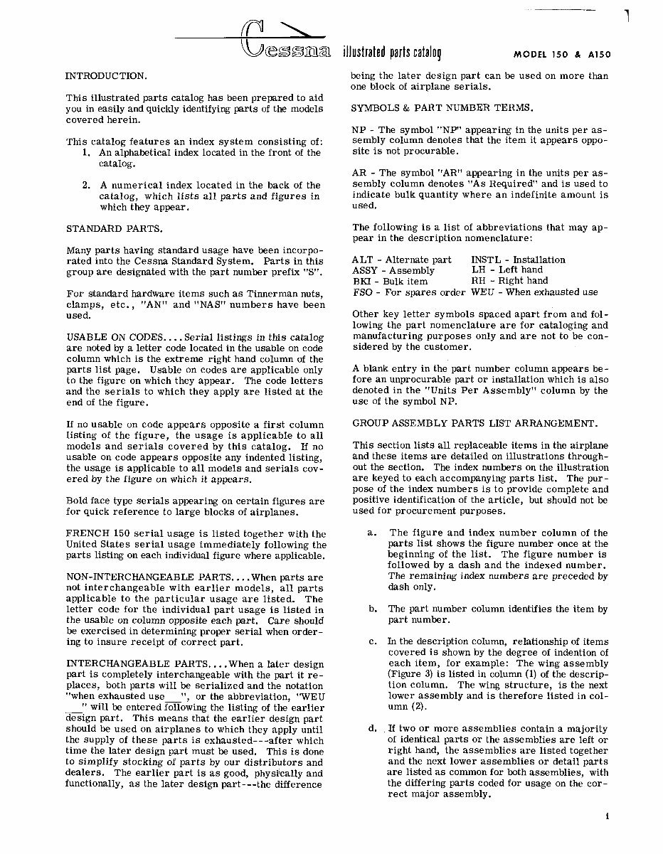
INTRODUCTION. This illustrated parts catalog has been prepared to aid you in easily and quickly identifying parts of the models covered herein. This catalog features an index system consisting of: 1. An alphabetical index located in the front of the catalog. 2. A numerical index located in the back of the catalog, which lists all parts and figures in which they appear. STANDARD PARTS. Many parts having standard usage have been incorpo- rated into the Cessna Standard System. Parts in this group are designated with the part number prefix "ST'. For standard hardware items such as Tinnerman nuts, clamps, etc., "AN" and "NAS" numbers have been used. USABLE ON CODES.. . .Serial listings in this catalog a r e noted by a letter code located in the usable on code column which is the extreme right hand column of the parts list page. Usable on codes are applicable only to the figure on which they appear. The code letters and the serials to which they apply are listed at the end of the figure. If no usable on code appears opposite a first column Iisting of the figure, the usage is applicable to all models and serials covered by this catalog. If no usable on code appears opposite any indented listing, the usage is applicable to all models and serials cov- ered by the figure on which it appears. Bold face type serials appearing on certain figures are for quick reference to large blocks of airplanes. FRENCH 150 serial usage is listed together with the United States serial usage immediately following the parts listing on each individual figure where applicable. NON-INTERCHANGEABLE PARTS. .. .When parts are not interchangeable with earlier models, all parts applicable to the particular usage are listed. The letter code for the individual part usage is listed in the usable on column opposite each part. Care should be exercised in determining proper serial when order- ing to insure receipt of correct part. INTERCHANGEABLE PARTS. . . .When a later design part is completely interchangeable with the part it re- places, both parts will be serialized and the notation "when exhausted use ", or the abbreviation, "WEU " will be entered following the listing of the earlier design part. This means that the earlier design part should be used on airplanes to which they apply until the supply of these parts is exhausted---after which time the later design part must be used. This is done to simplify stocking of parts by our distributors and dealers. The earlier part is a s good, physi'cally and functionally, as the later design part---the difference illustrated parts catalog MODEL 150 & A150 being the later design part can be used on more than one block of airplane serials. SYMBOLS & PART NUMBER TERMS. NP - The symbol "NP" appearing in the units per as- sembly column denotes that the item it appears oppo- site is not procurable. AR - The symbol "AR" appearing in the units per as- sembly column denotes "As Required" and is used to indicate bulk quantity where an indefinite amount is used. The following i s a list of abbreviations that may ap- pear in the description nomenclature: ALT - Alternate part INSTL - Installation ASSY - Assembly LH - Left hand BKI - Bulk item RH - Right hand FSO - For spares order WEU - When exhausted use Other key letter symbols spaced apart from and fol- lowing the part nomenclature are for cataloging and manufacturing purposes only and are not to be con- sidered by the customer. A blank entry in the part number column appears be- fore an unprocurable part or installation which is also denoted in the "Units Per Assembly'' column by the use of the symbol NP. GROUP ASSEMBLY PARTS LIST ARRANGEMENT. This section lists all replaceable items in the airplane and these items are detailed on illustrations through- out the section. The index numbers on the illustration are keyed to each accompanying parts list. The pur- pose of the index numbers is to provide complete and positive identification of the article, but should not be used for procurement purposes. The figure and index number column of the parts list shows the figure number once at the beginning of the list. The figure number is followed by a dash and the indexed number. The remaining index numbers are preceded by dash only. The part number column identifies the item by part number. In the description column, relationship of items covered is shown by the degree of indention of each item, for example: The wing assembly (Figure 3) is listed in column (1) of the descrip- tion column. The wing structure, is the next lower assembly and is therefore listed in col- umn (2). If two or more assemblies contain a majority of identical parts or the assemblies are left or right hand, the assemblies are listed together and the next lower assemblies or detail parts are listed as common for both assemblies, with the differing parts coded for usage on the cor- rect major assembly.
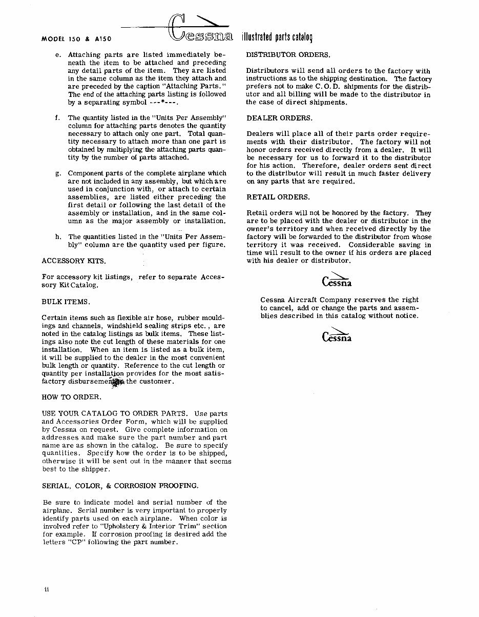
MODEL 150 & A150 e. Attaching parts are listed immediately be- neath the item to be attached and preceding any detail parts of the item. They are listed in the same column as the item they attach and are preceded by the caption "Attaching Parts." The end of the attaching parts listing is followed by a separating symbol ---*---. f. The quantity listed in the "Units Per Assembly" column for attaching parts denotes the quantity necessary to attach only one part. Total quan- tity necessary to attach more than one part is obtained by multiplying the attaching parts quan- tity by the number of parts attached. g. Component parts of the complete airplane which are not included in any assembly, but which are used in conjunction with, or attach to certain assemblies, are listed either preceding the first detail or following the last detail of the assembly or installation, and in the same col- umn as the major assembly or installation. h. The quantities listed in the "Units Per Assem- bly" column are the quantity used per figure. ACCESSORY KITS. For accessory kit listings, refer to separate Acces- sory Kit Catalog. BULK ITEMS. Certain items such as flexible air hose, rubber mould- ings and channels, windshield sealing strips etc., are noted in the catalog listings as bulk items. These list- ings also note the cut length of these materials for one installation. When an item is listed as a bulk item, it will be supplied to the dealer in the most convenient bulk length or quantity. Reference to the cut length or quantity per instal factory disbursem HOW TO ORDER. USE YOUR CATALOG TO ORDER PARTS. Use parts and Accessories Order Form, which will be supplied by Cessna on request. Give complete information on addresses and make sure the part number and part name are as shown in the catalog. Be sure to specify quantities. Specify how the order is to be shipped, otherwise it will be sent out in the manner that seems best to the shipper. SERIAL, COLOR, & CORROSION PROOFING. illustrated parts catalog DISTRIBUTOR ORDERS. Distributors will send all orders to the factory with instructions as to the shipping destination. The factory prefers not to make C. 0. D. shipments for the distrib- utor and all billing will be made to the distributor in the case of direct shipments. DEALER ORDERS. Dealers will place all of their parts order require- ments with their distributor. The factory will not honor orders received directly from a dealer. It will be necessary for us to forward it to the distributor for his action. Therefore, dealer orders sent direct to the distributor will result in much faster delivery on any parts that are required. RETAIL ORDERS. Retail orders will not be honored by the factory. They are to be placed with the dealer or distributor in the owner's territory and when received directly by the factory will be forwarded to the distributor from whose territory it was received. Considerable saving in time will result to the owner if his orders are placed with his dealer or distributor. 1 Cessna Cessna Aircraft Company reserves the right to cancel, add or change the parts and assem- blies described in this catalog without notice. L Cessna Be sure to indicate model and serial number of the airplane. Serial number is very important to properly identify parts used on each airplane. When color is involved refer to "Upholstery & Interior Trim" section for example. If corrosion proofing is desired add the letters "CP" following the part number.
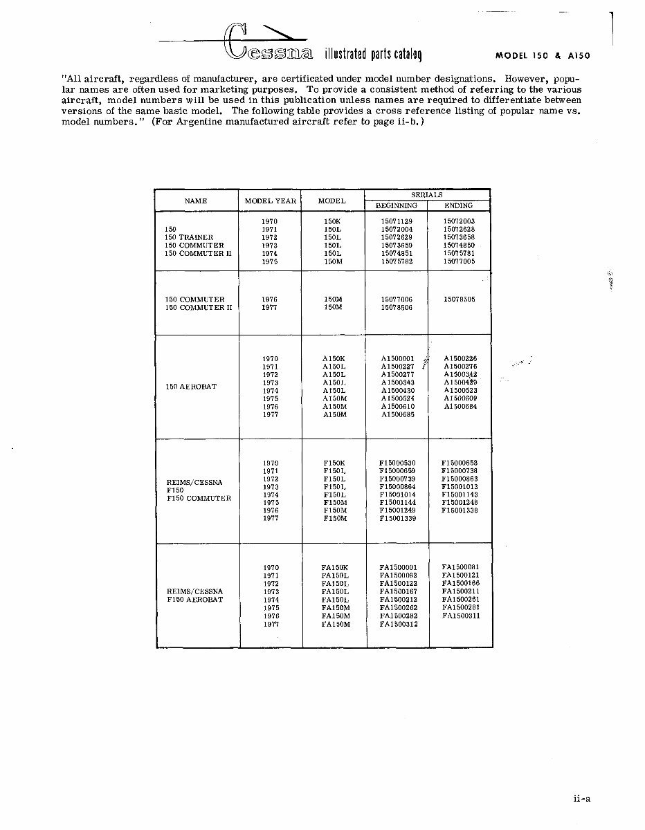
s illustrat~d parts catalog MODEL 150 8 A150 "All aircraft, regardless of manufacturer, are certificated under model number designations. However, popu- lar names are often used for marketing purposes. To provide a consistent method of referring to the various aircraft, model numbers will be used in this publication unless names are required to differentiate between versions of the same basic model. The following table provides a cross reference listing of popular name vs. model numbers. " (For Argentine manufactured aircraft refer to page ii-b. ) 150 TRAINER 150 COMMUTER 150 COMMUTER I1 SERIALS MODEL YEAR MODEL ENDING 15072003 15072628 15073658 15074850 15075781 15077005 BEGINNING 150 COMMUTER 150 COMMUTER I1 REIMS/CESSNA F150 F150 COMMUTER REIMS/CESSNA F150 AEROBAT ii-a
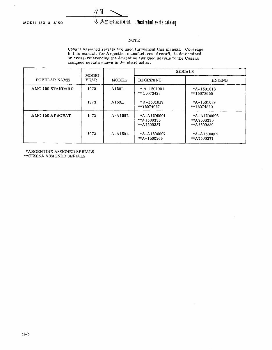
MODEL 150 8, A150 b illustrated parts tatalag NOTE Cessna assigned serials are used throughout this manual. Coverage in this manual, for Argentine manufactured aircraft, is determined by cross-referencing the Argentine assigned serials to the Cessna assigned serials shown in the chart below. POPULAR NAME AMC 150 STANDARD AMC 150 AEROBAT I MODEL *ARGENTINE ASSIGNED SERIALS **CESSNA ASSIGNED SERIALS SERIALS t YEAR 1972 ii-b MODEL A150L BEGINNING * A-1501001 ** 15073428 ENDING *A-1 501018 **I5073655
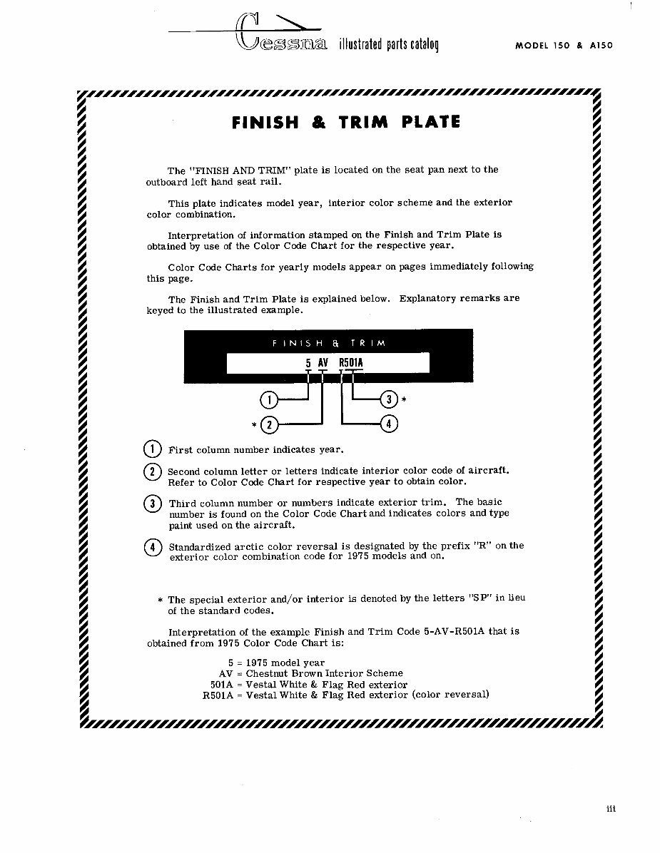
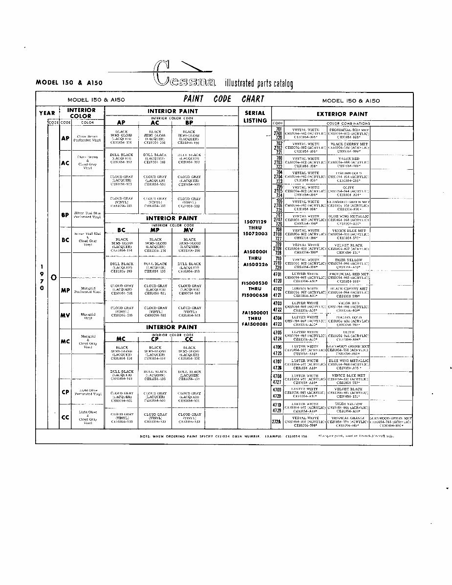
s illustrated parts catalog MODEL 150 & A150 FINISH & TRIM PLATE The "FINISH AND TRIMt1 plate is located on the seat pan next to the outboard left hand seat rail. This plate indicates model year, interior color scheme and the exterior color combination. Interpretation of information stamped on the Finish and Trim Plate is obtained by use of the Color Code Chart for the respective year. Color Code Charts for yearly models appear on pages immediately following this page. The Finish and Trim Plate is explained below. Explanatory remarks are keyed to the illustrated example. @ First column number indicates year. 2 Second column letter or letters indicate interior color code of aircraft. O Refer to Color Code Chart for respective year to obtain color. 3 Third column number or numbers indicate exterior trim. The basic O number is found on the Color Code Chart and indicates colors and type paint used on the aircraft. 4 Standardized arctic color reversal is designated by the prefix "R" on the 0 exterior color combination code for 1975 models and on. * The special exterior and/or interior is denoted by the letters "SP" in lieu of the standard codes. Interpretation of the example Finish and Trim Code 5-AV-R501A that is obtained from 1975 Color Code Chart is: 5 = 1975 model year AV = Chestnut Brown Interior Scheme 501A = Vestal White & Flag Red exterior R501A = Vestal White & Flag Red exterior (color reversal) iii
fl\ MODEL 150 a A150 b illustrated parts catalop MODEL 150 & A150 PAIN7 CODE CHAR1 MODEL 150 & A150 - YEAR OLOR SERIAL LISTING EXTERIOR PAINT COLOR COMBINATIONS BLACK SEMI-GLOSS (LACQUER) CESI054-156 701 VESTAL. WHITE I PROVINCIAL RED MET CES1054-398' CESL054-998. 702 VESTAL ~ 1 1 1 ~ ~ I BLACK CHERRY MET 2702 ~cEs10s4-mI (ACRYLIC) CES1054-964 (AC11YLIC)~ 791 CES1054-398. CES1054-909' DULL. BLACK (LACQUER) CESl054- 193 DULL BLACK ILACQUER) CES1054- 193 VALOR RED CI:S1054-398' CESl054- 40g1 ITALIAN (iOL.Il %p CES054-34 (ACRYLIC) CES1054-205- 705 VESTAL WHITE OMVE 2351 CES1054-802 IACKYLIC! CESl054-944 IACRYLIC) CES1054-39G1 CES1054-AM* cmun GRAY (LACQUER) CES1054-531 CLOUD GRAY (LACQUER) CES1054-531 CLOUD GRAY (LACQUER) CES1054-531 CLOUD GRAY (VINYL.) CESl054-533 CLOUD GRAY CES1054-533 CLOUD GRAY (VINYL) CES1054-533 I PAINT cEs~2~~& 2::LIc) :;tZZ!g& YE% : $ CES1054-398' CES1054-A05' VESTAL WIIITE VENICE BLUE MET 2708 CESlO54-802 (ACRYLIC) CES1054-833 IACRYLIC) 191 CESl054-398* CES1054-572- 15071129 THRU 15072003 1 - Sllvcr Tt'dl Blue LOR CODE MV I Cloud Gray BLACK BLACK vinyl -- BLACK I 709 VESTAL WHITE VELVET BLACK 1709 CES1054-802 (ACRYLIC) CES1054-807 (ACRYLIC) 728 CESl054-398' - CES1054-151' 710 VESTAL WHITE TIGER YELLOW 2710 CES1054-802 (ACRY1,IC) CE61054-966 IACRYLIC) 729 CES1054-398' - CES1054-A03' A1500001 THRU A1500226 DULL BLACK DULL BLACK 11 :;;::::2 1 ;;$?% DULL BLACK (LACQUER) CES1054-193 LUSTER WHITE PROVlNClAL RED MET 1701 CES1054-987 (ACRYLIC) CES1054-963 (ACRYLIC) 1720 CES1054-A10' - CES1054-988- LUSTER WHITE BLACK CHERRY MET fi;: CES1054-967 (ACRYLIC) CES1054-964 (ACRYLIC) CES1054-AlO* t CESL054-999. CLOUD GRAY (LACQUER) CES1054-531 C M U D GRAY (VINYL) CES1054-533 PAINT LOR CODE BLACK SEMI-GLOSS (LACQUER) CES1054 156 F15000530 THRU F15000658 CLOUD GRAY (LACQUER) CES1054-531 VALOR RED CES1054-409. .- CMUD GRAY Vinyl CLOUD GRAY (VINYL) CES1054-533 FA1500001 THRU FA1500081 - LUSTER WBI'I'E ITALIAN W L D CES1054~285' Marlgold BLACK SEMl&GLOSS IL.ACQUER) CESlOS4 156 LUSTER WHITE 1 ; : - 1CESlEg~4!~yLIC)~ES1054~~~~~CRYLIC!~ CkS1054-A04* BLACK SEMI-GLOSS (LACQUER) CES1054-156 LUSTER WHITE BLUE WING METALLIC I7O7 lCESl054-967 IACRYL1Cl CESl054-966 IACRYLIC)~ 1726 CES1054-A10* I CES1054-AO5. DULL BLACK (LACQUER) CES1054-193 DULL BLACK (LACQUER) CES1054-193 DULL DLACK (LACQUER) CES1054-193 LUSTER WHlTE VENICE BLUE MET 1 : ; ; ~cEsl:1,4!CFLIC) 1 CESL054-833 CLIO54-572. (ACRYL1C)I Llplit Ohve Perfozntcd vmyi C W U D GRAY I (LACQUER) CES1054-531 CMUD GRAY (LACQUER) CES1054- 531 CMUD GRAY (LACQUER) CES1054-531 LUSTER WHITE TIGER YELLOW "I0 CES1054-967 (ACRYLIC! CES1054-966 (ACRYLIC) 17 . I CESl054-110. I - CES1054-A031 LW Olive C1,OUD ' 11 IVINVLl Cloud tirzy vmyi CES1054-533 CLOUD GRAY (VINYL) CES1054-533 CLOUD GRAY (VINYL) CES1054-533 NOTE WHEN ORDERING PAINT SPECIFY CIS1054 DASH NUMBER EXAMPLE CtS1054.156 'Lirqucrprlnt, u5ediin FrencllAmr.~ftvllly
Get access to a comprehensive parts manual, parts list, and parts catalog featuring exploded diagrams for every part. This manual contains manufacturer part numbers and detailed diagrams, allowing you to enlarge views for even the smallest part. The exploded views are invaluable for assembly and disassembly assistance, making it a great tool for professionals and DIY enthusiasts alike.
All files are in PDF format, ensuring ease of readability and accessibility. This manual is designed to aid in disassembly and reassembly, providing a wealth of information on parts and numbers with accompanying exploded diagrams.
With instant delivery, there are no shipping costs or waiting for a physical manual to arrive. Upon payment completion through our secure processor, you will receive the manual instantly. It is compatible with both PC and MAC, working seamlessly with all versions of Windows.
Print what you need, when you need it – this is the only parts list manual you will ever need. Click on the instant download button to get this valuable resource today.
All rights reserved. Designated trademarks and brands are the property of their respective owners.