ii CHAMPION SERVICE MANUAL FORWft~D Thi s manual is provided as a guide to overhauling, mai ntaining and re - pairi ng the Champio n M odels 7ECA , 7GCAA, 7GCBC, and 7KCAB aircraft manufa c- ture d by Bel lanca Aircraft Corpora t ion, Alexandr ia, Minnesota at Osceo la, Wis co nsin . The informa ti on covered in this manual will concern only components man- uf ac tu red by B ellanca Aircraft Corpora ti on. I nf ormat i on necessary f or over- haul of the engi nes , radio, etc. , must be obtained from the manufacturer of t he individual component . The informa t ion compil ed in this manual will be kept current by revisions dis tr i buted through the factory. REVISIONS I. Temporary R evision This type of revis ion vall be distributed at any time it is nece ssary to forwar d new servic ing i nformation to the fi eld . This material should be inser t ed in the manual as soon as it is received . The temporary revisi ons may be in serted in the front of the manual. These revisions will include deletions and addi t ions of ma te rial pertinent to different parag raphs of the servi ce manual, there fore, when t he temporary revision is rec eived, review the manual and mark the affec ted para gra ph with the code date of the latest revisi on f or a ready reference. II. Permanent R evis i on This type of reVlSlon will be distribu t ed periodically and will super- cede all pr evi ous temporar y revisions . These revisions will be complet e page re placements and must be in serted in the servi ce manual with revi sed pa ges of the same pa ge number. III. Identifica t ion of R evised M aterial R evised text and illus trations will be indica t ed by a black ver t ical line along the left hand margin of the page opposit e the change . A line opposite the page number or secti on title and prin ting date will indica te that the text or illustra t ion ~as unchanged , but t he material was relo- ca t ed to a differen t page. Newly added ma t erial will be iden tif ied by an arrow po inting toward either the text , text heading or illustration . When material is r emove d, an arrow will point awa y from the area from which the material was removed. Symbo ls will i ndica te onl y current revis i ons with changes and addi- tions to or deletions of existing text and illus t rations . Changes in cap- italization, spel ling, pu nctuation or the physical location of th e material on the page will not be iden ti fied by symbols . Issued 7-2-73
CHAMPION SERVICE MANUAL TABLE OF CONTENTS PAGE I. DESC RIPTION. • • • • • • • • • • • • • • • • • • II . HANDLING AND SERVICING • III. INSPECTION • IV. STRUCTURES • V. SURF A CE CONTROLS AND RIGGING VI. LANDllJG GEAR AND BRArm SYSTEM • · . . . . . VII. POWERPLANT. VIII. FUEL SYSTEM . . . . IX . ELECTRICAL SYSTEM . . . . . . . . . . . . . . . . X. INSTRUMENTS. • • . . . . . . . . . . · . . . . . . XI. INSTALLATION, REPAIR AND FllJISHING OF FABRIC COVERING • • • • • • • • • • • Iss ued 7-2-73 · . . . . . . iii
CHAMPION SERVICE MANUAL SECTION I DESCRIPTION PAGE I-I. GENERAL 3 1-2. WING 3 1-3. EMPENNAGE 3 1-4. FUSELAGE 3 1-5. LANDING GEAR 4 1-6. BRAKE SYSTEMS 4 1-7. ENGINE AND PROPELLER 4 1-8. FUEL SYSTEMS 5 1-9. FLIGHT CONTROLS 5 1-10. CABIN HEATER AND FRESH-AIR SYSTEM 5 Iss ue d 7-2-73 1
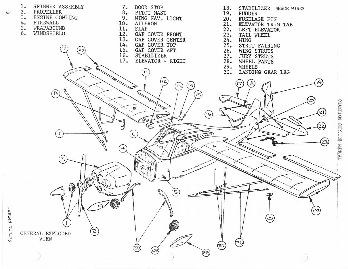
~ H Ul Ul s::: CD 0.. --J I 1. SPINNER ASSEMBLY 2G PROPELLER 3. ENGINE Cm-lLING 4 .. FlREHALL 5" WRAPAROUND 6. WINDSHIELD ~ GENERAL EXPLODED j V IEW ) 7. B. 9. 10. 11. 12. 13. 14. 15. 16. 17. DOOR STOP lB. PITOT MAST 19. WING NAV. LIGHT 20. AILERON 21. FLAP 22. GAP COVER FRONT 23. GAP COVER CENTER 24. GAP COVER TOP 25. GAP COVER AFT 26. STABILIZER 27. ELEVATOR - RIGHT 2B. 29. 30. STABILIZER BRACE WillES RUDDER FUSELAGE FIN ELEVATOR TRIH TAB LEFT ELEVATOR TAIL ¥lHEEL WING STRUT FAIRING WING STRUTS JURY STRUTS WHEEL PANTS v.THEELS LANDING GEAR LEG ') (") :::r:: ~ ~ ~ ~ ;:u ~ ~ ~ ;p t:-l
CHAMPICN SERVICE MANUAL SECTICN I DESCRIPTICN 1-1. GENERAL The Champion Citabria is a two-place tandem, strutbraced; high- wing monoplane. The fuselage is a welded steel frame covered with Dacron fabric. The wings are also Dacron covered and have wooden spars and ~ormed aluminum ribs. The aircraft is powered by a Ly- coming engine with a fixed pitch metal propeller. 1-2. WING The wings are of conventional construction with Sitka Spruce spars, formed aluminum ribs, dragwire bracing and covered with Dac- ron fabric. The ailerons and flaps are cable controlled. 1-3. EMPENNAGE The elevators are cable controlled and are aerodynamically balanced. The elevator trim tab is cable activated and located on the left elevator. The trim tab is of aluminum and utilizes a piano hinge attachment. The rudder is cable controlled and partially balanced. All surfaces a,re constructed of steel tubing and steel channels, and are fabric covered. 1-4. FUSELAGE Issued 7-2-73 The fuselage frame consists of a welded steel tubing assembly which forms the body of the fuselage. The external fuselage shape is formed by wooden bulkheads, stringers and formers which are at- tached to the frame. 3
CHAMPION SERVICE MANUAL 1- 5. LANDING GEAR The landing gear is of the fixed gear type consisting of two steel main gear legs and a steerable ta ilwheel. 1- 6. BRAKE SYSTEM The brakes are disc type , act ivated by hydraul ic systems which are inde pendentl y operated by heel or toe type brake pedals. 1-7 ENGINE AND PROPELLER The Model 7ECA is powered by a Lycoming 0- 235 -Cl engine. Rated continuous power is 115 h.p . @ 2800 RPM . The following table gives fac to ry approved propeller s: HODEL 7ECA LAND PLANE MANUF . McCauley MODEL lC90A1M72 or lC90CLM72 DIA . IN. 72 ALLOWABLE STATIC R.P.M . RANGE 2225- 2425 NaTE : STATIC RPM WILL INCREASE WITH INCREASING OAT . APPROX. PITCH RANGE-IN. 46-50 The 7GCAA and 7GCBC are powered by a Lycoming 0-3 20-A2B engine . The 7KCAB is powered by a Lycoming I0-320 - E2A engine. R ated power i s 150 H. P. @ 2700 RPM . The following tables give all factory approved propellers. MODEL 7GCAA & 7GCBC LAND PLANE ALLOWABLE STATIC APPROX. PITCH MANUF . MODEL DIA. IN. R. P.M. RANGE RANGE- IN. -- McCauley lC172AGM 72 2300- 2640 50 - 60 Sensenich 74DM6S8-2 72 2300-2640 50 - 60 Sensenich 74DM6S8-1 73 2300-2640 48-60 MODEL 7KCAB LAND PLANE ALLOWABLE STATIC APPROX . PITCH MANUF . M ODEL DIA. IN . R.P .M. RANGE RANGE- IN. -- McCauley lC172AGM 72 2300-2540 50-60 S.ensenich 74DM6S 8- 2 72 2300- 2540 50 - 60 Se n senic h 74DM6S8 -1 73 2300-25 40 48- 56 NOTE : ST ATI C RPM WILL INCRE ASE WITH INCREASING OAT . NaTE : REFER TO SECTION 6- 18 FOR PROP . LENGTH LIMITATIONS. 4 Issued 7-2-73
CHAMPION SERVICE MANUAL 1-8. FUEL SYSTEM The fuel system consists of two, 18 gallon formed & welded aluminum wing tanks on Models 7ECA, 7GCBC, 7KCAB and 7 GCAA or two standard 13 gallon wing tanks on pre 1974 Model 7ECA. The tanks are cross-fed and cross-vented. Fuel is gra vity fed to the engine. 1-9. FLIGHT CONTROLS The flight controls ar e conventional consisting of a control stick which operates the ailerons and elevators and foot pedals which operate the rudder. Duplicate controls are pro vided for the co-pilot. 1-10. CABIN HEAT AND FRESH-AIR SYSTEM The heated air for the cabin is obtained directly from the exhaust system muffler shroud. Fresh a ir is taken from ven ts on the sides of the fuselage and on the left side window. 1974 models also include adjustable upper right (or optional left) wing root fresh air vent. Issued 9-1-74 5
CHAMPION SERVICE MANUAL SECTION II HANDLING AND SERVICING PAGE 2-l. GENERAL 7 2-2. ACCESS PROVISIONS 7 2- 3. GROUND HANDLI NG 8 2-4. HOISTING 8 2-5. LEVELING 9 2-6 . WEIGHING PROCEDURE 10 2-7. M OORING 11 2-8 . PARK BRAKES 11 2-9. LOCKING AIRCRAFT 11 2-10. DRAINING FUEL SYSTEM 11 2- 11 . FILLING AND BLEEDING HYDRAULIC BRAKES 12 2- 12. L UBRI CATI ON 12 2-13. RECOMMENDED ENGINE OIL 12 2-14. FILLING ENGINE SUMP 15 2-15. DRAINING ENGINE S UMP 15 2-16. BATTERY SERVICING 15 AIRCRAFT SPECIFICATIONS AND PRINCIPAL DIMENSIONS 17 6 Issued 7-2-73
Thank you for considering this comprehensive Workshop Service Repair Manual for the Bellanca Champion Citabria 7ECA, 7GCAA, 7GCBC, 7KCAB Aircraft.
This manual is an invaluable resource for both professional mechanics and DIY enthusiasts, covering every service and repair procedure with easy-to-follow step-by-step instructions and detailed illustrations.
By utilizing this manual, you can significantly reduce repair costs by performing maintenance and repairs on your own. The manual is yours to keep forever, allowing you to print specific pages, chapters, or the entire document. Additionally, it can be conveniently accessed on your tablet or smartphone.
Models Covered:
All Models/Engines/Trim/Transmissions Types Are Covered
Contents:
This high-quality Service Repair Workshop Manual covers all repair procedures A-Z
Every repair and service procedure is comprehensively detailed
Computer Requirements:
This manual is compatible with all PC & MAC Computers, tablets, and mobile phones
The only software needed is Adobe Reader, which is typically pre-installed or can be downloaded for free
Delivery:
This manual will be instantly emailed to the address provided during checkout after payment via Visa, MasterCard, or PayPal
Customer satisfaction is guaranteed with this Workshop Service Repair Manual.