

beechcraft Bonanza 36 35 parts & service manual
What's Included?
Fast Download Speeds
Offline Viewing
Access Contents & Bookmarks
Full Search Facility
Print one or all pages of your manual

Bonanza
iileechcraft
F33A
SERIALS CE-613 THRU CE-;I;I1
EXCEPT CE~748
Bonanza Bonanza Bonanza
F33C
V35B A36
SERIALS CJ1105
SERIALS D8818
SERIALS E-710,
THRU CJ-148
THRU P10119
E1763 THRU 6-1240
EXCEPT D-10097
EXCEPT E-llll
"0~~
WIRING
DIAGRAM MANUAL
14 VOLT ELECTRICAL SYSTEM
COPYRIGKT 0
BEECH 1982
P/N 35-590102-78
P/N 35~f~0102-1Bi
Reissued:
April 28, 1916 Revised: September 3, 1982

PUBLISHED BY
COMMERCIAL PUBLICATIONS
BEECH AIRCRAFT CORPORATION
WICHITA, KANSAS 67201
U. S. A.
~3eechrxaft
8
Mamb´•r ol GAMA
GenaralPlviation
A
~Py~hson Company Monufacturere Alloti.lion
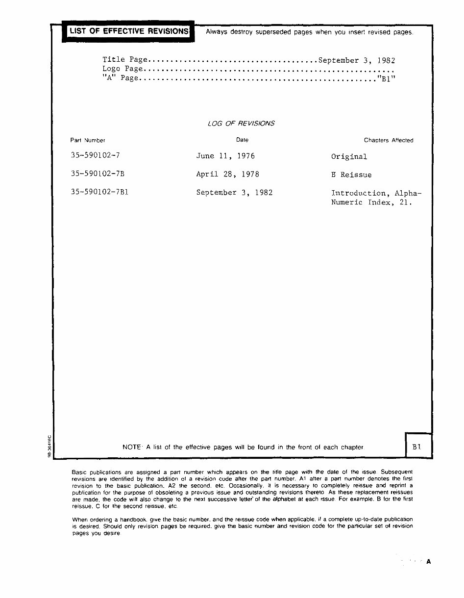
LIST OF EFFECTIVE
REVISIONSI Always destroy superseded pages
when
you
inser: revised
pages.
Title
Page......................................September
3,
1982
Logo Page........................................................
"A"
Page. ................... ................... ..,...,......."B1"
LOG OF R~1~SIONS
Part Number Date
Chapters Affected
35-590102-7 June
11,
1976
Original
35-590102-7B
April 28, 1978 B Reissue
35-590102-7B1
September 3,
1982
Introduction, Alpha-
Numeric
Index,
21.
NOTE: A list of the etfective
pages
will be found in the front of each
chapter I
st
Basic publications are assigned a part
number which
appears
on the title
page
with the date of the issue. Subsequent
revisions are identified
by
the addition of a revision code alter the
part
number. Al after a part
number denotes the first
revision to the basic publication.
A2 the second. etc. Occasionally.
it is
necessary
to completely
reissue and reprint a
publication for the
purpose
of
obsoleting a previous issue and outstanding revisions thereto As these replacement reissues
are made, the code will also change
to the next successive letteiol the alphabet at each issue. For
example.
B for the first
reissue, C for the second reissue. etc.
When ordering a handbook, give the basic number. and the reissue code when
applicable.
if a complete up-to-date publication
is desired. Should only revision
pages
be required. give
the basic number and revision code for the particular set of revision
pages you
desire
BEECHCRAFT
BONANZA
WIRING DIAGRAM MANUAL
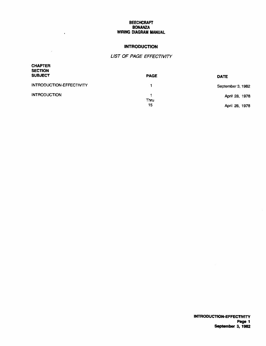
INTRODUCTION
LIST OF PAGE EFFECTII~N
CHAPTER
SECTION
SUBJECT
PAGE
DATE
INTRODUCTION-EFFECTIVITY 1
September 3, 1982
INTRODUCTION 1
April 28, 1978
Thru
15
April 28, 1978
INTRODUCnON-EFFECTIVm
Page
1
September 3, 1982
BEECHCRAFT
BONANZA
WIRING DIAGRAM MANUAL
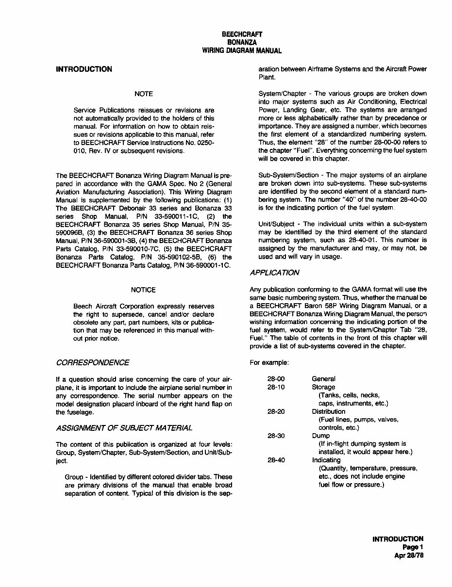
INTRODUCTION aration between Airframe
Systems
and the Aircraft Power
Plant.
NOTE System/Chapter The various
groups
are broken down
into
major systems
such as Air
Conditioning,
Electrical
Service Publications reissues or revisions are Power, Landing Gear, etc. The
systems
are
arranged
not
automatically provided
to the holders of this more or less
alphabetically
rather than
by precedence or
manual. For information on how to obtain reis-
importance. They are assigned a number, which becomes
sues or revisions
applicable
to this manual, refer the first element of a standardized
numbering system.
to BEECHCRAFT Service Instructions No. 0250- Thus, the element "28" of the number 28-00-00 refers to
010, Rev. IV or
subsequent
revisions. the
chapter
"Fuel".
Everything concerning
the fuel
system
will be covered in this
chapter.
The BEECHCRAFT Bonanza
Wiring Diagram
Manual is
pre- Sub-System/Section The
major systems
of an
airplane
pared
in accordance with the GAMA
Spec.
No 2
(General
are broken down into
sub-systems.
These
sub-systems
Aviation
Manufacturing Association).
This
Wiring Diagram
are identified
by
the second element of a standard num-
Manual is
supplemented by
the
following publications: (1) bering system.
The number "40" of the number 28-40-00
The BEECHCRAFT Debonair 33 series and Bonanza 33 is for the
indicating portion
of the fuel
system.
series Shop Manual, P/N 33-590011-1C, (2)
the
BEECHCRAFT Bonanza 35 series
Shop Manual, P/N 35- Unit/Subject The individual units within a sub-system
5900968, (3)
the BEECHCRAFT Bonanza 36 series
Shop may
be identified
by
the third element of the standard
Manual, P/N 36-590001-38, (4)
the BEECHCRAFT Bonanza numbering system,
such as 28-40-01. This number is
Parts
Catalog,
P/N 33-590010-7C, (5)
the BEECHCRAFT assigned by
the manufacturer and
may,
or
may
not, be
Bonanza Parts
Catalog,
P/N 35-590102-58, (6)
the used and will
vary
in
usage.
BEECHCRAFT Bonanza Parts
Catalog,
P/N 36-590001-1C.
APPLICATION
NOTICE Any publication conforming
to the GAMA format will use the
same basic
numbering system. Thus, whether the manual be
Beech Aircraft
Corporation expressly
reserves a BEECHCRAFT Baron 58P
Wiririg´• Diagram Manual, or a
the
right
to
supersede,
cancel and/or declare BEECHCRAFT Bonanza
Wiring Diagram Manual, the
perso?
obsolete
any part, part numbers, kits or publica- wishing
information
concerning
the
indicating portion
of the
tion that
may
be referenced in this manual with- fuel
system,
would refer to the
System/Chapter
Tab "28,
out
prior
notice. Fuel." The table of contents in the front of this
chapter
will
provide a list of
sub-systems
covered in the
chapter.
CORRESPONDENCE For
example:
If a question
should arise
concerning
the care of
your
air- 28-00 General
plane,
it is
important
to include the
airplane
serial number in 28-10
Storage
any correspondence.
The serial number
appears
on the (Tanks, cells, necks,
model
designation placard
inboard of the
right
hand
flap on caps, instruments, etc.)
the
fuselage.
28-20 Distribution
(Fuel lines, pumps,
valves,
ASSIGNMENT OF SUBJECT MA TERIAL controls, etc.)
28-30
Dump
The content of this
publication
is
organized
at four levels: (If in-flight dumping system
is
Group, System/Chapter, Sub-System/Section,
and Unit/Sub- installed, it would
appear here.)
ject.
28-40
Indicating
(Quantity, temperature, pressure,
Group Identified
by
different colored divider tabs. These etc., does not include
engine
are primary
divisions of the manual that enable broad fuel flow or pressure.)
separation
of content.
Typical
of this division is the
sep-
INTRODUCTION
Pagel
Apr
28/78
BEECHCRAFT
BONANUI
WIRING DIAGRAM MANUAL
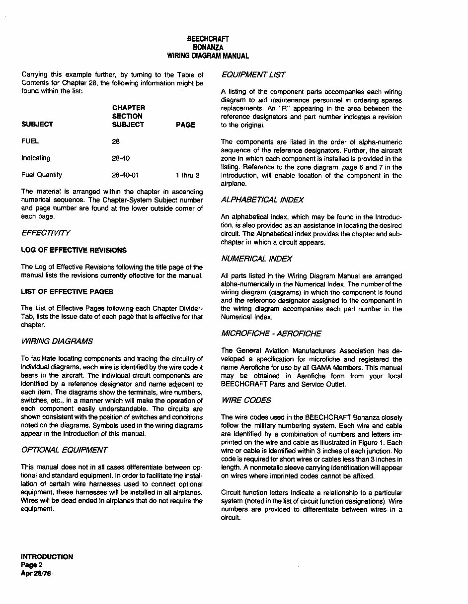
Carrying
this
example further, by turning
to the Table of EQUIPMENTLIST
Contents for
ChaFjter 28, the
following
infonation
might
be
found within the list: A
listing
of the
component parts accompanies
each
wiring
diagram
to aid maintenance
personnel
in
ordering spares
CHAPTER
replacements.
An "R"
appearing
in the area between the
SECTION reference
designators
and
part
number indicates a revision
SUBJECT SUBJECT PAGE to the
original.
FUEL 28 The
components are listed in the order of
alpha-numeric
sequence
of the reference
designators. Further, the aircraft
Indicating 28-40 zone in which each
component
is installed is
provided
in the
listing.
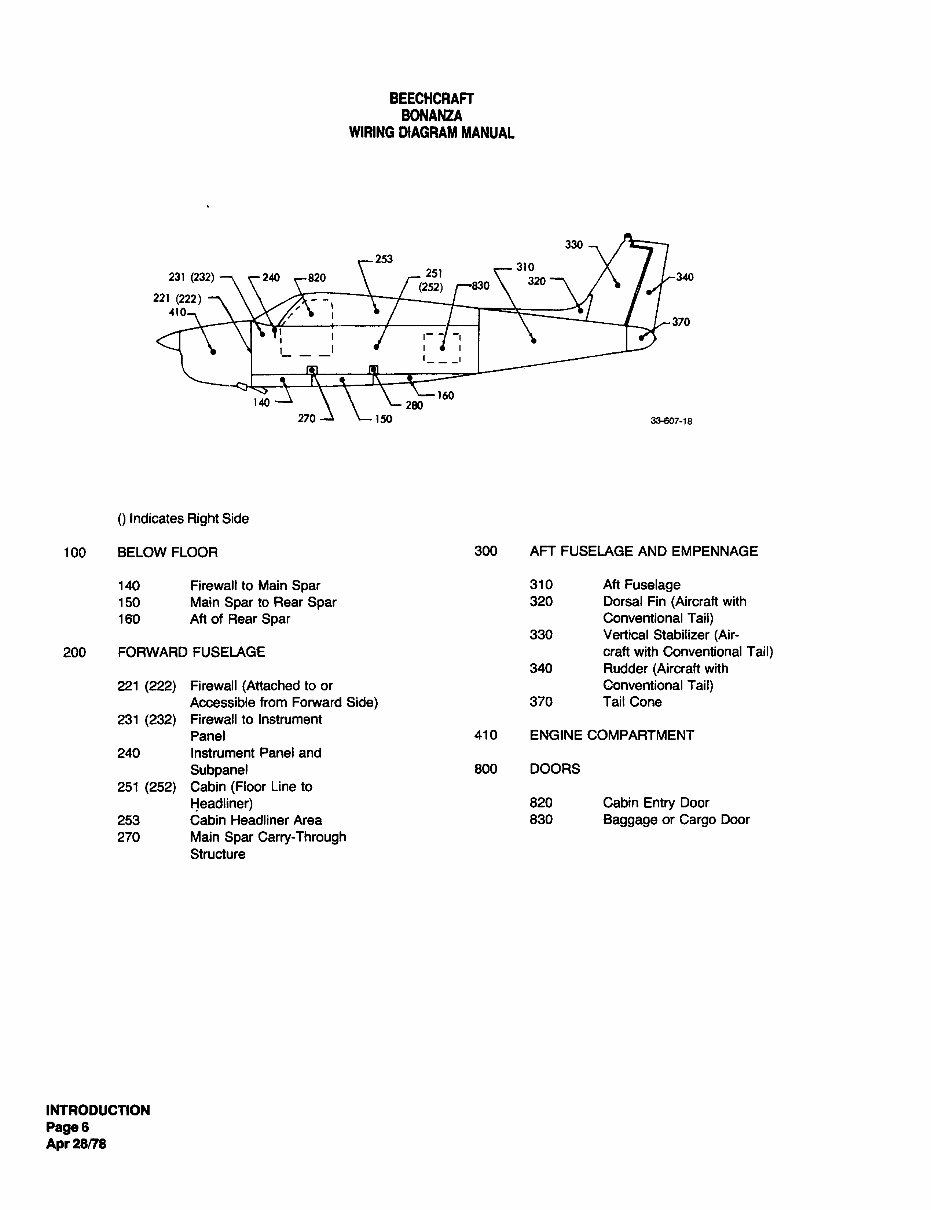
Reference to the zone
diagram, page
6 and 7 in the
Fuel
Quantity 28-40-01 1 thru 3 Introduction, will enable location of the
component
in the
airplane.
The material is
arranged
within the
chapter
in
ascending
numerical
sequence.
The
Chapter-System Subject
number ALPHABETIGAL INDEX
and
page
number are found at the lower outside corner of
each
page.
An
alphabetical index, which
may
be found in the Introduc-
tion, is also
provided as an assistance in
locating
the desired
EFFECnVIN circuit. The
Alphabetical index
provides
the
chapter
and sub-
chapter
in which a circuit
appears.
LOG OF EFFECTIVE REVISIONS
NUMERICAL INDEX
The
Log
of Effective Revisio~o~s
following
the title
page
of the
manual lists the revisions
currently
effective for the manual. All
parts
listed in the
Wiring Diagram
Manual are arranged
alpha-numerically in the Numerical Index. The number of the
LIST OF EFFECTIVE PAGES
wiring diagram (diagrams)
in which the
component
is found
and the reference
designator assigned
to the
component
in
The List of Effective
Pages following
each
Chapter
Divider- the
wiring diagram accompanies
each
part
number in the
Tab, lists the issue date of each
page
that is effective for that Numerical Index.
chapter.
MICROFI%HE -AEROFIGHE
WIRING DIAGRAMS
The General Aviation Manufacturers Association has de-
To facilitate
locating components
and
tracing
ihe
circuitry
of
veloped a
specification
for microfiche and
registered
the
individual
diagrams,
each wire is identified
by
the wire code it name Aerofiche for use
by
all GAMA Members. This manual
beam in the aircraft. The individual circuit
components are may
be obtained in Aerofiche form from
your
local
identified
by
a reference
designator
and name
adjacent
to BEECHCRAFT Parts and Service Outlet.
each item. The
diagrams
show the terminals, wire numbers,
switches, etc.,
in a manner which will make the
operation
of WIF~E CODES
each
component easily
understandable. The circuits are
shown consistent with the
position
of switches and conditions The wire codes used in the BEECHCRAFT Bonanza
closely
noted on the
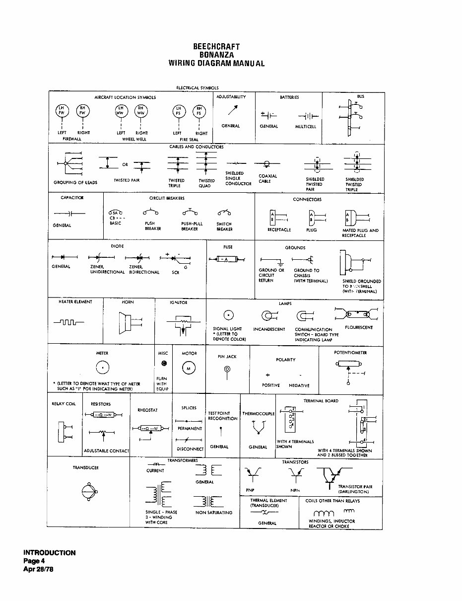
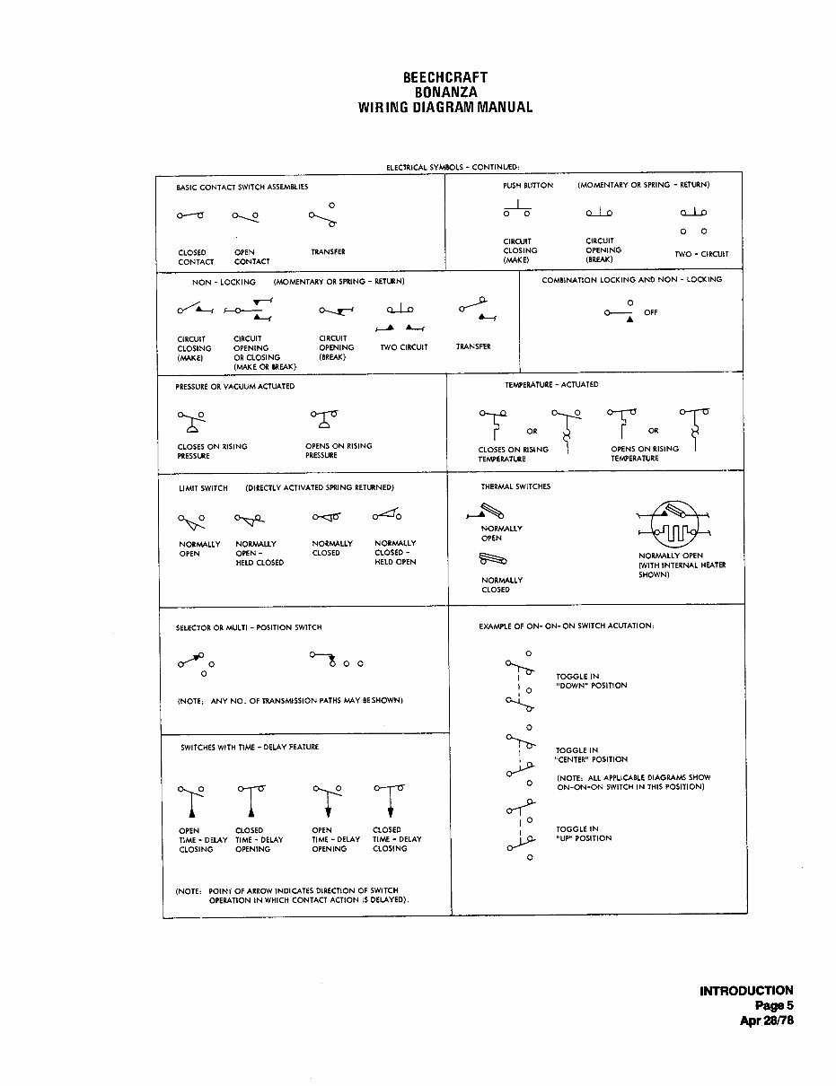
diagrams. Symbols
used in the
wiring diagrams
follow the
military numbering system.
Each wire and cable
appear
in the introduction of this manual. are identified
by a combination of numbers and letters im-
printed on the wire and cable as illustrated in
Figure
i. Each
OP;TIONAL EQUIPMENT wire or cable is identified within 3 inches of each
junction.
No
code is
required
for short wires or cables less than 3 inches in
This manual does not in all cases differentiate between
op- length.
A nonmetalic sleeve
carrying
identification will
appear
tional and standard
equipment.
In order to facilitate the instal- on wires where
imprinted
codes cannot be affixed.
lation of certain wire harnesses used to connect
optional
equipment,
these harnesses will be installed in all
airplanes.
Circuit function letters indicate a relationship to a particular
Wires will be dead ended in
airplanes
that do not
require
the
system (noted
in the list of circuit function
designations).
Wire
equipment. numbers are provided
to differentiate between wires in a
circuit.
INTRODUCTION
Page
2
Apr 28n8
BEECHCRAFT
BONANZA
WIRING DIAGRAM MANUAL
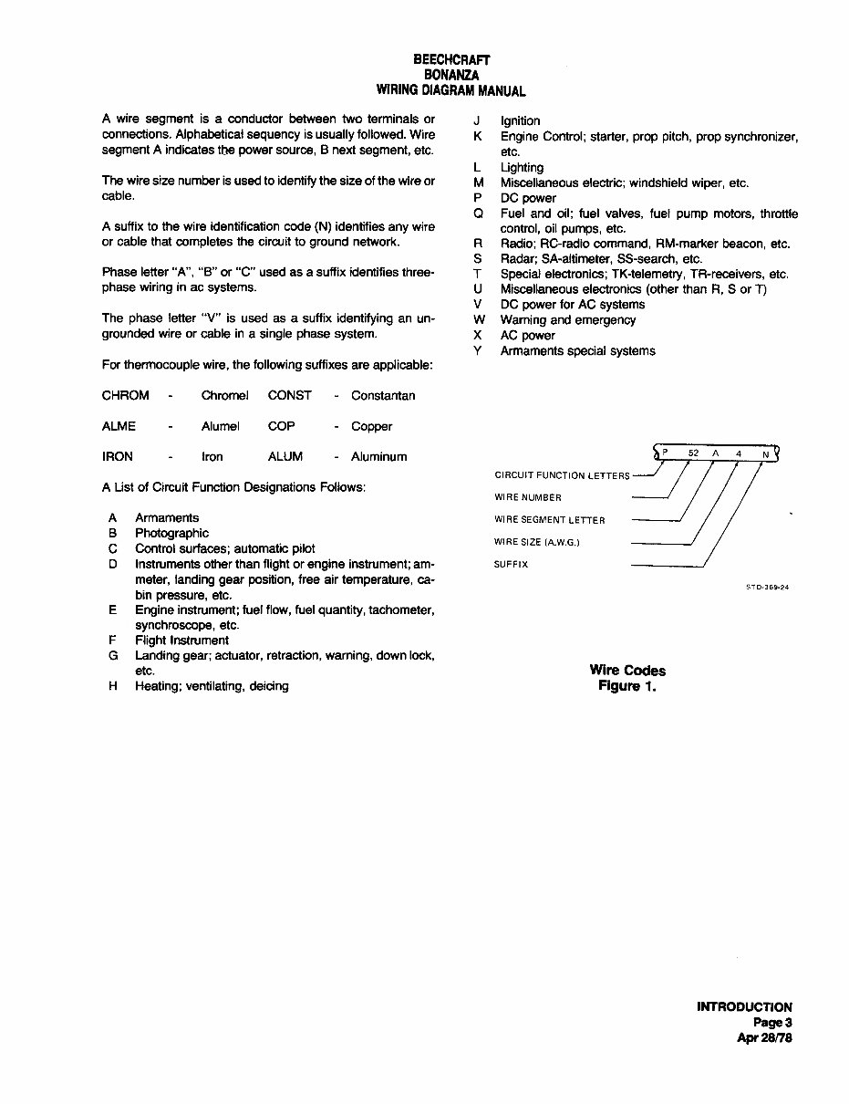
A wire
segment
is a conductor between two terminals or J
Ignition
connections.
Alphabetical sequency
is
usually
followed. Wire
K
Engine Control; starter, prop pitch, prop synchronizer,
segment
A indicates the
power source,
B next
segment,
etc.
etc.
L
Lighting
The wire size number is used to
identify
the size of the wire or M Miscellaneous electric; windshield
wiper,
etc.
cable.
P DC
power
Q Fuel and oil; fuel valves, fuel
pump motors, throttle
A suffix to the wire identification code
(N)
identifies
any
wire
control, oil
pumps,
etc.
or cable that
completes
the circuit to
ground
network.
R Radio; RC-radio command, RM-marker beacon, etc.
S Radar; SA-altimeter, SS-search, etc.
Phase letter "A", "B" or "C" used as a suffix identifies three- T
Special electronics; TK-telemetry, TR-receivers, etc.
phase wiring
in ac
systems. U Miscellaneous electronics
(other
than R, S or T)
V DC
power
for AC
systems
The
phase
letter "V" is used as a suffix
identifying
an un- W
Warning andemergency
grounded
wire or cable in a single phase system. X AC
power
Y Armaments
special systems
For
thermocouple wire, the
following
suffixes are applicable:
CHROM Chromel CONST Constantan
ALME Alumel COP
Copper
IRON Iron ALUM Aluminum
~P
52
CIRCUIT FUNCTION LETTE RS
A List of Circuit Function
Designations
Follows:
WIRE NUMBER
A Armaments WIRE SEGMENT LETTE R
B
Photographic
WIRESIZE (A.W.G.)
C Control surfaces; automatic
pilot
D Instruments other than
flight
or
engine instrument; am- SUFFIX
meter, landing gear position,
free air
temperature, ca-
5TD´•369´•24
bin
pressure,
etc.
E
Engine instrument; fuel flow, fuel
quantity, tachometer,
synchroscope,
etc.
F
Flight
Instrument
G
Landing gear; actuator, retraction, warning,
down lock,
etc. Wire Codes
H
Heating; ventilating, deicing Figure 1.
INTRODUCTION
Page
3
Apr
28/78
BEECHCRAFT
BONANZA
WIRING DIAGRAM MANUAL
ELECTRICAL SYMBOLS
AIRCRAFT LOCATION SYMBOLS ADJUSTABILITY BATTERIES
BUS
QQ
O~ww
QQ
~
-111~
GENERAL GENERAL MULTICELL
LEFT RIGHT LEFT RIGHT LEFT RIGHT
FIREWALL WHEEL WELL FIRE SEAL
CABLES AND CONDUCTORS
~ r-r if
SHIELDED
conxlAL
SINGLE SHIELDED SHIELDED TWISTED PAIR TWISTED TWISTED CABLE
GROUPING OF LEADS
CONDUCTOR TWISTED TWISTED
TRIPLE OUAD
PAIR TRIPLE
CAPACITOR CIRCUIT BREAKERS
CONNECTORS
GENERAL
ba a~b 6~/5
~ ~ ~
cB~~~
BASIC PUSH PUSH-PULL SWITCH
BREAKER BREAKER BREAKER RECEPTACLE PLUG MATED PLUG AND
RECEPTACLE
DIODE
FUSE GROUNDS
´•-L~nI~r
tL ~-~F
GENERAL ZENE~ ZENER G
GROUND OR GROUND TO
UNIDIRECTIONAL BIDIRECTIONAL SCR
CIRCUIT CHASSIS
RETUIN (WITH TERMINAL) SHIELD GROUNDED
TO 8:TKSHeLL
C~,r~, iWMINAL)
HEATER ELEMENT HORN IGNITOR
LAMPS
-~n~G
I
o m
T~c~ ^^^ ’
Ilcr’
SIGNAL LIGHT INUINDESCENT COMMUNICATION
FLOURESCENT
’(LETTER TO SWITCH
BOARD TYPE
DENOTE COLOR) INDICATING LAMP
METER MISC I MOTOR
POTENTIOMETW
PIN JACK
POLARITY
O
eB
O~----(
FURN
(LETTER TO DENOTE WHAT TYPE OF METER WITH
POSITIVE NEGATIVE
SUCH AS "I" FOR INDICATING METER) EOUIP
TERMINAL BOARD
RELAYCOIL RESISTORS
SPLICES
r~T1
RHEOSTAT
tcI~-~3~
TESTPOINT TnERMOtOUPLE
´•--´•´•´•‘4~~*
rl
~
tNfi
~
t-f--~
WITHITERMINALS
GENERAL GENERAL SHOWN
I
I
ADJUSTABLE CONTACT) I
DISCONNECT
WITH 4 TERMINALS SHOWN
AND Z BUSSED TOGETHER
TRANSFORMERS
TRANSISTORS
--FC~--
’U~~"’
’"’"’
3f
ti ~fT
1~
GENERAL
(TRANSDUCER)
T Tl~elNII~TORP*III
PNP NPN
(DARLINGTON)
311~
TR[sYL II(MINI COll~ OTHIITI~N RIV\YI
SINGLE PHASE NON SATURATING -----~X~--
TYn?
rrm
3-WINDING
WITH CORE
GENERAL
WINDINGS. INDUCTOR
REACTOR OR CHOKE
INTRODUCTION
Page4
Apr
28n8
BEECHCRAFT
BONANZA
WIRING DIAGRAM MANUAL
ELECTRICAL SYMBOLS CONTINUED:
BASIC CONTACT SWITCH ASSEMBLIES
PUSH BUTTON (MOMENTARY OR SPRING
RETURN)
Oa
I
o o ~Lo ~D
o o
CIRCUIT CIRCUIT
CLOSED OPEN TRANSFER CLOSING OPENING
TWO-CIRCUIT
CONTACT CONTACT (MAKE) (BREAK)
NON LOCKING (MOMENTARY OR SPRING
RETURN) COMBINATION LOCKING AND NON LOCKING
bLT
i~O--T( ~Lo
~P
~
,Pi
4 L-r
CIRCUIT CIRCUIT CIRCUIT
CLOSING OPENING OPENING TWO CIRCUIT TRANSFER
(MAKE) OR CLOSING (BREAK)
(MAKE OR BREAK)
PRESSURE OR VACUUM ACTUATED
TEMPERATURE ACTUATED
4T´•´•~
~
oR
CLOSES ON RISING OPENS ON RISING
OPENS ON RISING CLOSES ON RISING
PRESSURE PRESSURE
TEMPERATURE TEMPERATURE
LIMIT SWITCH (DIRECTLY ACTIVATED SPRING RETURNED) THERMAL SWITCHES
~
"o"
~ "
OPEN
NORMALLY NORMALLY NORMALLY NORMALLY
OPEN OPEN CLOITD CLOlsD
Noahu\lLY OPEN
HELD CLOSED HELD OPEN
(wlTH INTERNAL HEATER
SHOWN)
NORMALLY
CLOSED
SELECTOR OR MULTI POSITION SWITCH EXAMPLE OF ON- ON-ON SWITCH ACUTATION:
~P
o
%..
O
TOGGLE IN
"DOWN" POSITION
(NOTE: ANY NO. OF TRANSMISSION PATHS Me,Y BCSHOWN)
SWITCHES WITH TIME DELAY FEATVRE
TOGGLE IN
kp
"CENTER" POSITION
(NOTE: ALL APPLICABLE DIAGRAMS SHOW
"r’ g" "r’ S"
ON-ON-ON SWITCH IN THIS POSITION)
OPEN CLOSED OPEN CLOSED I TOGGLEIN
TIME- DTV\Y nMI-DEUY TIME-DLUY TIML-DPPIY
DlP
"UP* POSITION
CLOSING OPENING OPENING CLOSING
(NOTE: POINI OF ARROW INDICATES DIRECTION OF SWITCH
OPERATION tN WHICH CONTACT ACTION IS DELAYED).
INTRODUCTION
Page
5
Apr
28/78
BEECHCRAFT
BONANZA
WIRING DIAGRAM MANUAL
330
253
310
231(232)7 ~-240 ~820
320’1 /~ /
~340
221
(222)
--
41
/ I
370
I
I- -I
I ’
’---I
160
140
280
270
--~
~150
33~607-18
()
indicates
Right
Side
100 BELOW FLOOR 300 AFT FUSELAGE AND EMPENNAGE
140 Firewall to Main
Soar
310 Aft
Fuselage
150 Main
Soar
to Rear
Soar
320 Dorsal Fin
(Aircraft
with
Aft of Rear
Soar
Conventional
Tail)
330 Vertical Stabilizer
(Air-
200 FORWARD FUSELAGE craft with Conventional
Tail)
340 Rudder
(Aircraft
with
221
(222)
Firewall
(Attached
to or Conventional
Tail)
Accessible from Forward
Side)
370 Tail Cone
231(232)
Firewall to Instrument
Panel 410 ENGINE COMPARTMENT
240 Instrument Panel and
Subpanel
800 DOORS
251
(252)
Cabin (Floor
Line to
Headliner)
820 Cabin
Entry
Door
253 Cabin Headliner Area 830
Baggage
or
Cargo
Door
270 Main
Spar Carry-Through
Structure
INTRODUCTION
Page
6
Apr
28n8
You're Reading a Preview
What's Included?
Fast Download Speeds
Offline Viewing
Access Contents & Bookmarks
Full Search Facility
Print one or all pages of your manual
$48.99
Viewed 17 Times Today


Secure transaction
What's Included?
Fast Download Speeds
Offline Viewing
Access Contents & Bookmarks
Full Search Facility
Print one or all pages of your manual
$48.99
This is a comprehensive maintenance and parts manual for the 35/36 Bonanza, suitable for professional mechanics and DIY enthusiasts. The revision date is June 2005, covering a range of essential information:
- Bonanza 36 Series Library
- Illustrated Parts Catalog
- Maintenance Manual
- Service Information and ADs
- Shop Manual
- Wiring Diagram Manual
- Illustrated Parts Catalog Bonanza 36, A36, A36TC, B36TC
- Maintenance Manual Bonanza V35B; F33A; F33C; A36; A36TC; B36TC
- Service Information and ADs 36 Series
- Shop Manual Bonanza 36 Series
- Wiring Diagram Manual Bonanza F33A, -F33C, -V35B, -A36 14volt System
- Bonanza F33A,-F33C,-V35B,-A36,-A36TC,-B36TC 28Volt System
- Bonanza A36; B36TC 28Volt Electrical System
Please note that this manual is in .PDF format.


