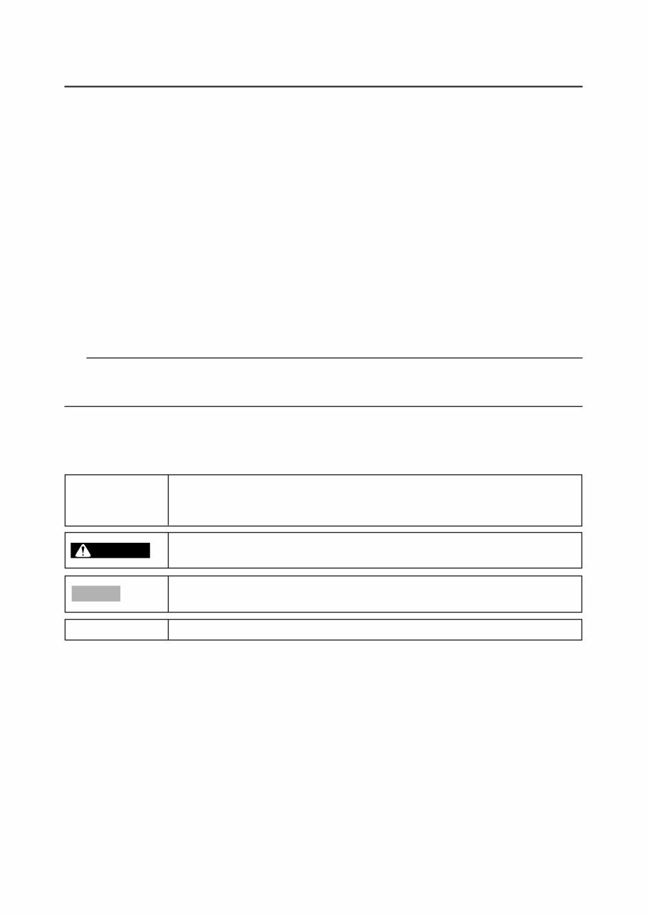
EAS20070 IMPORTANT This manual was produced by the Yamaha Motor Taiwan Company, Ltd. primarily for use by Yamaha dealers and their qualified mechanics. It is not possible to include all the knowledge of a mechanic in one manual. Therefore, anyone who uses this book to perform maintenance and repairs on Yamaha vehicles should have a basic understanding of mechanics and the techniques to repair these types of vehicles. Repair and maintenance work attempted by anyone without this knowledge is likely to render the vehicle unsafe and unfit for use. This model has been designed and manufactured to perform within certain specifications in regard to performance and emissions. Proper service with the correct tools is necessary to ensure that the vehicle will operate as designed. If there is any question about a service procedure, it is imperative that you contact a Yamaha dealer for any service information changes that apply to this model. This policy is intended to provide the customer with the most satisfaction from his vehicle and to conform to federal environmental quality objectives. Yamaha Motor Taiwan Company, Ltd. is continually striving to improve all of its models. Modifications and significant changes in specifications or procedures will be forwarded to all authorized Yamaha dealers and will appear in future editions of this manual where applicable. TIP • This Service Manual contains information regarding periodic maintenance to the emission con- trol system. Please read this material carefully. • Designs and specifications are subject to change without notice. EAS20080 IMPORTANT MANUAL INFORMATION Particularly important information is distinguished in this manual by the following notations. This is the safety alert symbol. It is used to alert you to potential personal injury hazards. Obey all safety messages that follow this symbol to avoid possible injury or death. A WARNING indicates a hazardous situation which, if not avoided, could result in death or serious injury. A NOTICE indicates special precautions that must be taken to avoid damage to the vehicle or other property. A TIP provides key information to make procedures easier or clearer. Q TIP WARNING NOTICE
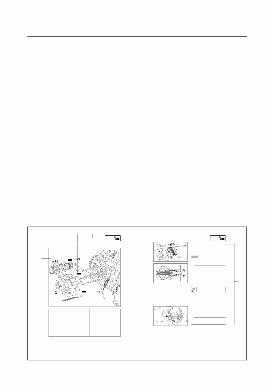
ENG 5-33 EAS00253 REMOVING THE CYLINDER AND PISTON 1. Remove: 8piston pin clip 1 8piston pin 2 8piston 3 NOTICE Do not use a hammer to drive the piston pin out. TIP 8 Before removing the piston pin clip, cover the crankcase opening with a clean rag to prevent the piston pin clip from falling into the crankcase. 8 Before removing the piston pin, deburr the piston pin clip’s groove and the piston’s pin bore area. If both areas are deburred and the piston pin is still difficult to remove, re- move it with the piston pin puller set4. Piston pin puller set 90890-01304(YU-01304) CYLINDER AND PISTON 2. Remove: 8top ring 82nd ring 8oil ring TIP When removing a piston ring, open the end gap with your fingers and lift the other side of the ring over the piston crown. 1 3 2 3 2 4 5-32 ENG Remarks Order Job/Part Q’ty 1 2 3 4 5 6 7 8 EAS00251 CYLINDER AND PISTON Removing the cylinder and piston Cylinder head Timing chain guide(exhaust side) Cylinder Dowel pin Cylinder gasket Piston pin clip Piston pin Piston Piston ring set Remove the parts in the order listed. Refer to”CYLINDER HEAD”. Refer to”REMOVING THE CYLINDER AND PISTON” and “INSTALLING THE PISTON AND CYLINDER”. For installation, reverse the removal pro- cedure. 1 1 2 1 2 1 1 1 CYLINDER AND PISTON 5 4 4 4 7 6 5 8 2 3 3 4 1 New New New EAS00007 HOW TO USE THIS MANUAL This manual is intended as a handy, easy-to-read reference book for the mechanic. Comprehensive explanations of all installation, removal, disassembly, assembly, repair and check procedures are laid out with the individual steps in sequential order. 1 The manual is divided into chapters. An abbreviation and symbol in the upper right corner of each page indicate the current chapter. Refer to “SYMBOLS”. 2 Each chapter is divided into sections. The current section title is shown at the top of each page, except in Chapter 3 (“PERIODIC CHECKS AND ADJUSTMENTS”), where the sub-section title(s) appears. 3 Sub-section titles appear in smaller print than the section title. 4 To help identify parts and clarify procedure steps, there are exploded diagrams at the start of each removal and disassembly section. 5 Numbers are given in the order of the jobs in the exploded diagram. A circled number indicates a disassembly step. 6 Symbols indicate parts to be lubricated or replaced.Refer to “SYMBOLS”. 7 A job instruction chart accompanies the exploded diagram, providing the order of jobs, names of parts, notes in jobs, etc. 8 Jobs requiring more information (such as special tools and technical data) are described se- quentially. 8 4 5 7 1 3 2 6
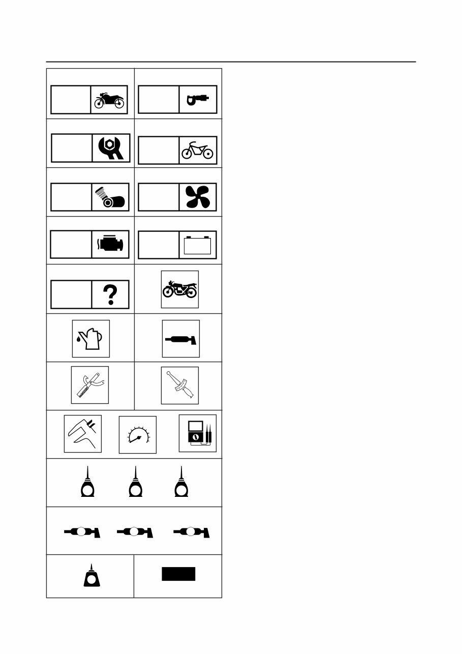
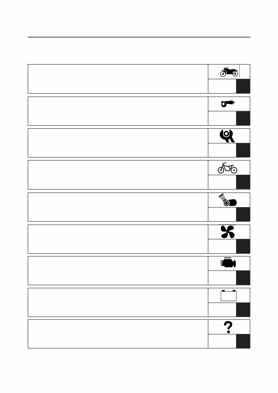
GEN INFO SPEC CHK ADJ ENG TRBL SHTG FI CHAS - + ELEC 4 M B LS New M G COOL 1 2 3 4 5 6 7 8 9 0 q w e r i o p a s d f g EAS00008 SYMBOLS The following symbols are not relevant to every vehicle. Symbols 1 to 9 indicate the subject of each chapter. 1 General information 2 Specifications 3 Periodic checks and adjustments 4 Chassis 5 Engine 6 Cooling system 7 Fuel injection system 8 Electrical system 9 Troubleshooting Symbols 0 to u indicate the following. 0 Serviceable with engine mounted q Filling fluid w Lubricant e Special tool r Tightening torque t Wear limit, clearance y Engine speed u Electrical data Symbols i to d in the exploded diagrams indi- cate the types of lubricants and lubrication points. i Engine oil o Gear oil p Molybdenum-disulfide oil a Wheel-bearing grease s Lithium-soap- based grease d Molybdenum-disulfide grease Symbols f to g in the exploded diagrams indi- cate the following. f Apply locking agent (LOCTITE ® ) g Replace the part T R . . t y u LT
EAS00010 TABLE OF CONTENTS GENERAL INFORMATION SPECIFICATIONS PERIODIC CHECKS AND ADJUSTMENTS CHASSIS ENGINE COOLING SYSTEM FUEL INJECTION SYSTEM ELECTRICAL SYSTEM TROUBLESHOOTING - + GEN INFO SPEC CHK ADJ CHAS ENG FI ELEC TRBL SHTG COOL 1 2 3 4 5 6 5 7 8 9
GEN INFO CHAPTER 1 GENERAL INFORMATION SCOOTER IDENTIFICATION ................................................................... 1-1 VEHICLE IDENTIFICATION NUMBER ............................................. 1-1 MODEL LABEL .................................................................................. 1-1 IMPORTANT INFORMATION ................................................................... 1-2 PREPARATION FOR REMOVAL AND DISASSEMBLY ................... 1-2 REPLACEMENT PARTS ................................................................... 1-2 GASKETS, OIL SEALS AND O-RINGS ............................................ 1-2 LOCK WASHERS/PLATES AND COTTER PINS ............................. 1-3 BEARINGS AND OIL SEALS ............................................................ 1-3 CIRCLIPS ........................................................................................... 1-3 EQUIPMENT PREPARATION ........................................................... 1-4 CHECKING THE CONNECTIONS ........................................................... 1-5 SPECIAL TOOLS ...................................................................................... 1-6
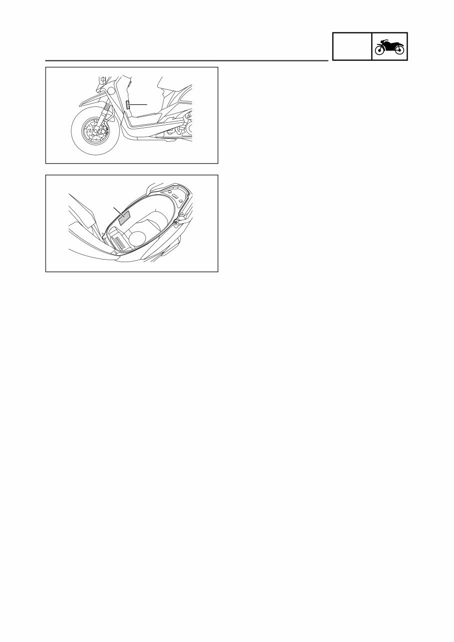
1-1 GEN INFO SCOOTER IDENTIFICATION EAS00015 GENERAL INFORMATION SCOOTER IDENTIFICATION EAS00017 VEHICLE IDENTIFICATION NUMBER The vehicle identification number 1 is stamped into the frame. EAS00018 MODEL LABEL The model label 1 is affixed to the frame trunk. This information will be needed to order spare parts. 1 1
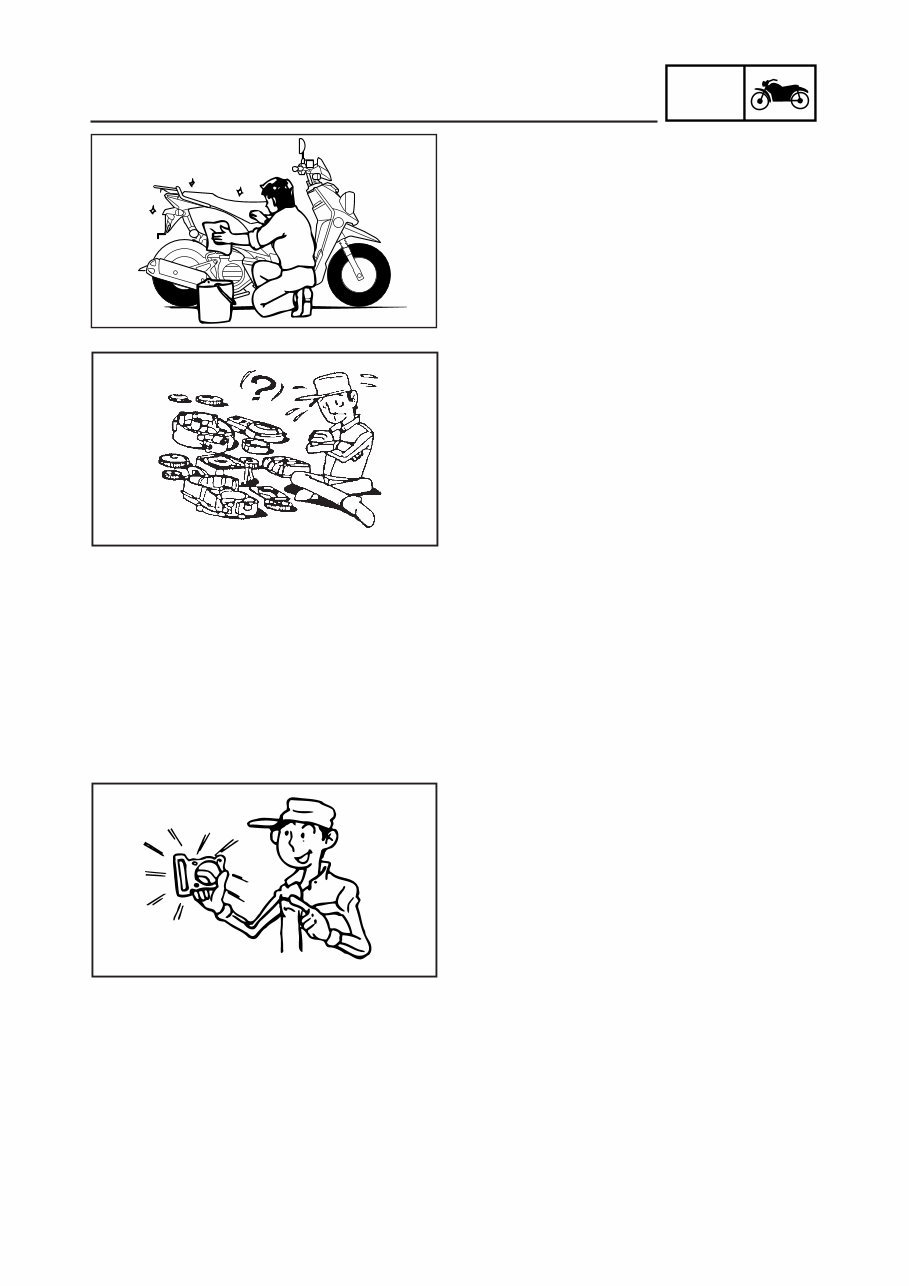
1-2 GEN INFO IMPORTANT INFORMATION EAS00020 IMPORTANT INFORMATION PREPARATION FOR REMOVAL AND DISAS- SEMBLY 1. Before removal and disassembly, remove all dirt, mud, dust and foreign material. 2. Use only the proper tools and cleaning equipment. Refer to the “SPECIAL TOOLS”. 3. When disassembling, always keep mated parts together. This includes gears, cylin- ders, pistons and other parts that have been “mated” through normal wear. Mated parts must always be reused or replaced as an assembly. 4. During disassembly, clean all of the parts and place them in trays in the order of dis- assembly. This will speed up assembly and allow for the correct installation of all parts. 5. Keep all parts away from any source of fire. EAS00021 REPLACEMENT PARTS Use only genuine Yamaha parts for all replace- ments. Use oil and grease recommended by Yamaha for all lubrication jobs. Other brands may be similar in function and appearance, but infe- rior in quality. EAS00022 GASKETS, OIL SEALS AND O-RINGS 1. When overhauling the engine, replace all gaskets, seals and O-rings. All gasket sur- faces, oil seal lips and O-rings must be cleaned. 2. During reassembly, properly oil all mating parts and bearings and lubricate the oil seal lips with grease.
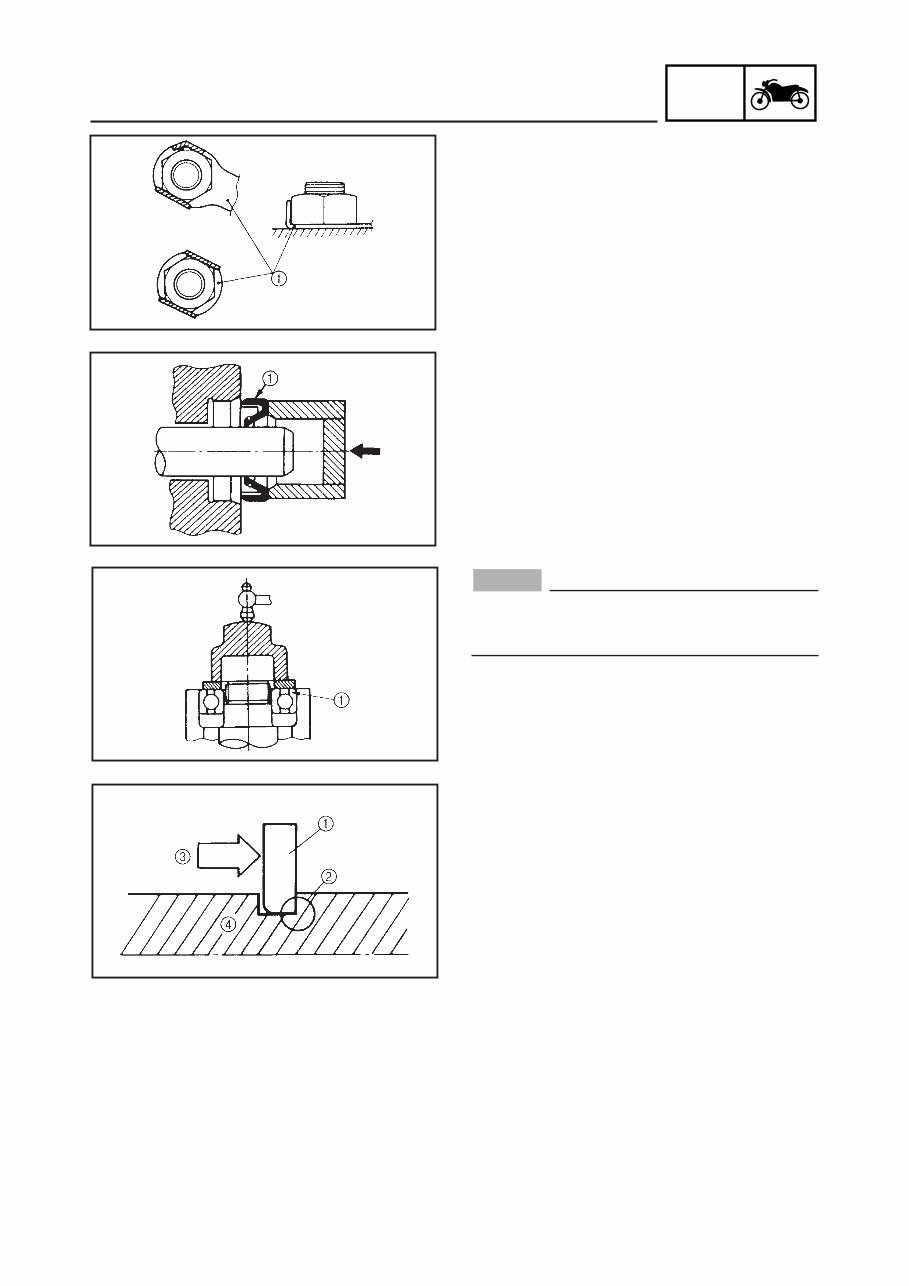
1-3 GEN INFO IMPORTANT INFORMATION EAS00023 LOCK WASHERS/PLATES AND COTTER PINS After removal, replace all lock washers/plates 1 and cotter pins. After the bolt or nut has been tightened to specification, bend the lock tabs along a flat of the bolt or nut. EAS00024 BEARINGS AND OIL SEALS Install bearings and oil seals so that the manufacturer’s marks or numbers are visible. When installing oil seals, lubricate the oil seal lips with a light coat of lithium-soap-based grease. Oil bearings liberally when installing, if appropriate. 1 Oil seal NOTICE Do not spin the bearing with compressed air because this will damage the bearing surfaces. 1 Bearing EAS00025 CIRCLIPS Before reassembly, check all circlips carefully and replace damaged or distorted circlips. Al- ways replace piston pin clips after one use. When installing a circlip 1, make sure the sharp-edged corner 2 is positioned opposite the thrust 3 that the circlip receives. 4 Shaft
You're Reading a Preview
What's Included?
Lifetime Access
Fast Download Speeds
Online & Offline Access
Access PDF Contents & Bookmarks
Full Search Facility
Print one or all pages of your manual
$31.99
2002-2011 Yamaha YW50 Zuma BWS Service & Repair Manual
Our service repair workshop manual is a comprehensive guide supplied in an easy-to-read format, covering all repairs from A-Z and all models. It is a valuable resource for both professional mechanics and DIY enthusiasts.
The manual covers major repair topics in great detail and includes high-quality pictures and diagrams for easy understanding. It encompasses maintenance and servicing, engine and clutch, transmissions, cooling systems, fuel and exhaust, ignition and electrical, brakes and brake assembly, wheels and tires, steering and suspension, frame and bodywork, wiring diagrams, fault finding troubleshooting, and much more.
Delivered instantly, this professional-quality information allows you to fix issues without delay. The manual is compatible with all operating systems, including PC and MAC, such as Windows 95, 98, 2000, Me, Xp, Vista, and Windows 7.
Get your hands on this invaluable resource by clicking the instant download button for a safe and fast transaction.
Reviews
Q&A
Recently Viewed
5,521,897Happy Clients
2,594,462eManuals
1,120,453Trusted Sellers
15Years in Business
Price:
Actual Price:
2002-2011 Yamaha YW50 Zuma BWS Service & Repair Manual




 Lifetime Access




