EAS20070 IMPORTANT This manual was produced by the Yamaha Motor Taiwan Company, Ltd. primarily for use by Yamaha dealers and their qualified mechanics. It is not possible to include all the knowledge of a mechanic in one manual. Therefore, anyone who uses this book to perform maintenance and repairs on Yamaha vehicles should have a basic understanding of mechanics and the techniques to repair these types of vehicles. Repair and maintenance work attempted by anyone without this knowledge is likely to render the vehicle unsafe and unfit for use. This model has been designed and manufactured to perform within certain specifications in regard to performance and emissions. Proper service with the correct tools is necessary to ensure that the vehicle will operate as designed. If there is any question about a service procedure, it is imperative that you contact a Yamaha dealer for any service information changes that apply to this model. This policy is intended to provide the customer with the most satisfaction from his vehicle and to conform to federal environmental quality objectives. Yamaha Motor Taiwan Company, Ltd. is continually striving to improve all of its models. Modifications and significant changes in specifications or procedures will be forwarded to all authorized Yamaha dealers and will appear in future editions of this manual where applicable. TIP • This Service Manual contains information regarding periodic maintenance to the emission con- trol system. Please read this material carefully. • Designs and specifications are subject to change without notice. EAS20080 IMPORTANT MANUAL INFORMATION Particularly important information is distinguished in this manual by the following notations. This is the safety alert symbol. It is used to alert you to potential personal injury hazards. Obey all safety messages that follow this symbol to avoid possible injury or death. A WARNING indicates a hazardous situation which, if not avoided, could result in death or serious injury. A NOTICE indicates special precautions that must be taken to avoid damage to the vehicle or other property. A TIP provides key information to make procedures easier or clearer. Q TIP WARNING NOTICE
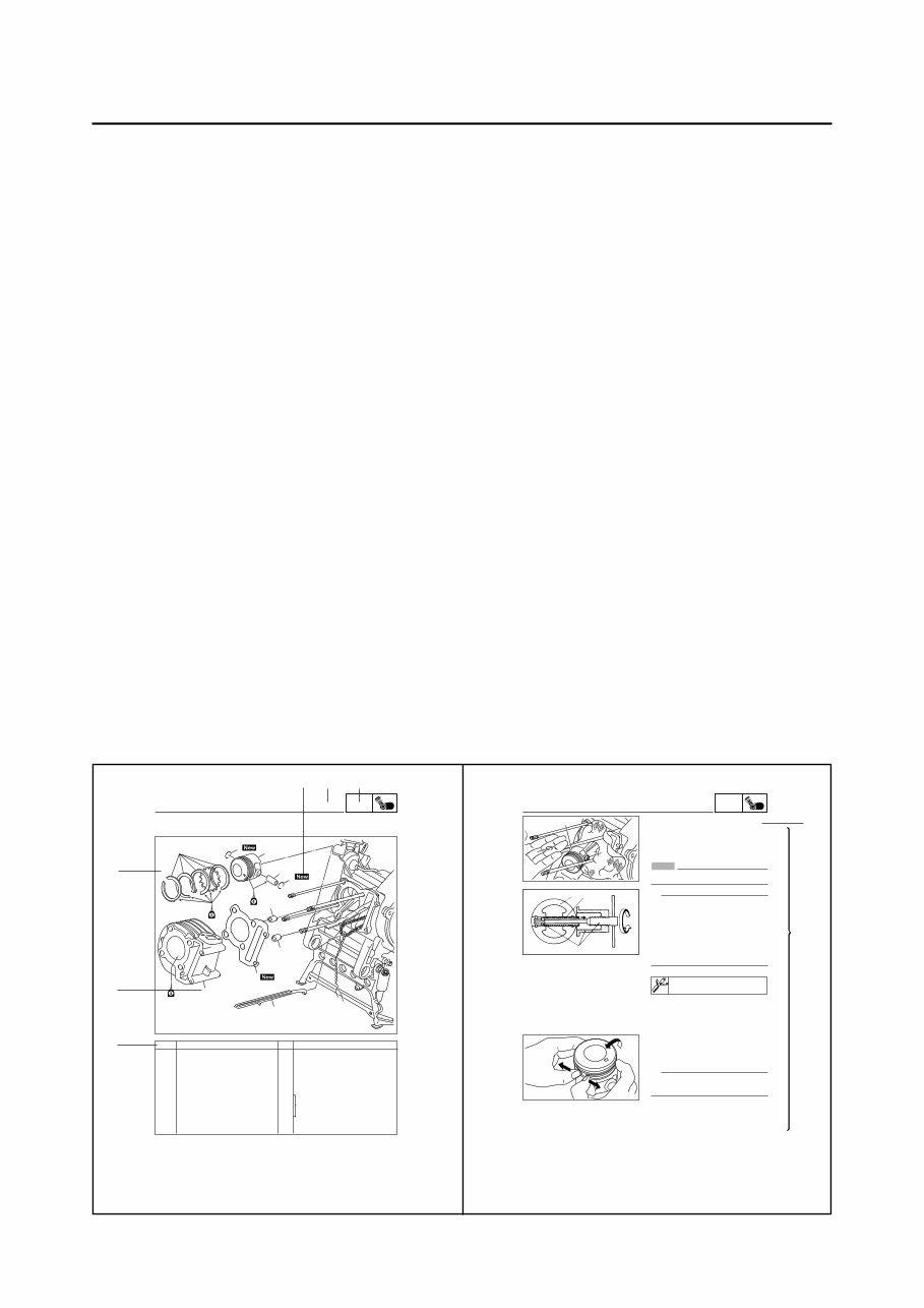
EAS00007 HOW TO USE THIS MANUAL This manual is intended as a handy, easy-to-read reference book for the mechanic. Comprehensive explanations of all installation, removal, disassembly, assembly, repair and check procedures are laid out with the individual steps in sequential order. 1 The manual is divided into chapters. An abbreviation and symbol in the upper right corner of each page indicate the current chapter.] Refer to “SYMBOLS”. 2 Each chapter is divided into sections. The current section title is shown at the top of each page, except in Chapter 3 (“PERIODIC CHECKS AND ADJUSTMENTS”), where the sub-section title(s) appears. 3 Sub-section titles appear in smaller print than the section title. 4 To help identify parts and clarify procedure steps, there are exploded diagrams at the start of each removal and disassembly section. 5 Numbers are given in the order of the jobs in the exploded diagram. A circled number indicates a disassembly step. 6 Symbols indicate parts to be lubricated or replaced. Refer to “SYMBOLS”. 7 A job instruction chart accompanies the exploded diagram, providing the order of jobs, names of parts, notes in jobs, etc. 8 Jobs requiring more information (such as special tools and technical data) are described se- quentially. 5-32 ENG Remarks Order Job/Part Q’ty 1 2 3 4 5 6 7 8 EAS00251 CYLINDER AND PISTON Removing the cylinder and piston Cylinder head Timing chain guide (exhaust side) Cylinder Dowel pin Cylinder gasket Piston pin clip Piston pin Piston Piston ring set Remove the parts in the order listed. Refer to “CYLINDER HEAD”. Refer to “REMOVING THE CYLINDER AND PISTON” and “INSTALLING THE PISTON AND CYLINDER”. For installation, reverse the removal pro- cedure. 1 1 2 1 2 1 1 1 CYLINDER AND PISTON 5 8 6 5 3 3 4 2 1 7 ENG 5-33 3 2 1 EAS00253 REMOVING THE CYLINDER AND PISTON 1. Remove: 8piston pin clip 1 8piston pin 2 8piston 3 NOTICE Do not use a hammer to drive the piston pin out. TIP 8 Before removing the piston pin clip, cover the crankcase opening with a clean rag to prevent the piston pin clip from falling into the crankcase. 8 Before removing the piston pin, deburr the piston pin clip’s groove and the piston’s pin bore area. 8 If both areas are deburred and the piston pin is still difficult to remove, remove it with the piston pin puller set 4. Piston pin puller set 90890-01304 (YU-01304) CYLINDER AND PISTON 2. Remove: 8top ring 82nd ring 8oil ring TIP When removing a piston ring, open the end gap with your fingers and lift the other side of the ring over the piston crown. 3 2 4 4 5 7 6 2 1 3 8
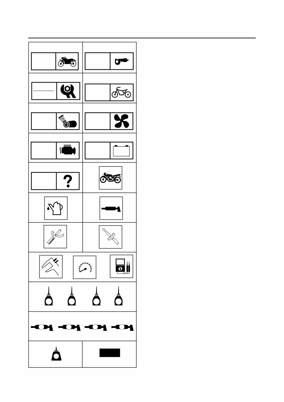
GEN INFO SPEC CHK ADJ ENG TRBL SHTG CHAS - + ELEC 4 M B LS New M G COOL 1 2 3 4 5 6 7 8 9 0 q w e r i s h j EAS00008 SYMBOLS The following symbols are not relevant to every vehicle. Symbols 1 to 9 indicate the subject of each chapter. 1 General information 2 Specifications 3 Periodic checks and adjustments 4 Chassis 5 Engine 6 Cooling system 7 Fuel injection system 8 Electrical system 9 Troubleshooting Symbols 0 to u indicate the following. 0 Serviceable with engine mounted q Filling fluid w Lubricant e Special tool r Tightening torque t Wear limit, clearance y Engine speed u Electrical data Symbols i to g in the exploded diagrams indi- cate the types of lubricants and lubrication points. i Engine oil o Gear oil p Molybdenum-disulfide oil a Brake fluid s Wheel-bearing grease d Lithium-soap- based grease f Molybdenum-disulfide grease g Silicone grease Symbols h to j in the exploded diagrams indi- cate the following. h Apply locking agent (LOCTITE ® ) j Replace the part T R . . t y u LT BF o p a S d f g FI
EAS00011 TABLE OF CONTENTS GENERAL INFORMATION SPECIFICATIONS PERIODIC CHECKS AND ADJUSTMENTS CHASSIS ENGINE FUEL INJECTION SYSTEM ELECTRICAL SYSTEM TROUBLESHOOTING - + GEN INFO SPEC CHK ADJ CHAS ENG FI ELEC TRBL SHTG 1 2 3 4 5 6 7 8
GEN INFO CHAPTER 1 GENERAL INFORMATION SCOOTER IDENTIFICATION ................................................................... 1-1 VEHICLE IDENTIFICATION NUMBER ............................................. 1-1 MODEL LABEL .................................................................................. 1-1 FEATURES ............................................................................................... 1-2 OUTLINE OF THE FI SYSTEM ......................................................... 1-2 FI SYSTEM ........................................................................................ 1-3 O 2 sensor ............................................................................................ 1-4 IMPORTANT INFORMATION ................................................................... 1-5 PREPARATION FOR REMOVAL AND DISASSEMBLY ................... 1-5 REPLACEMENT PARTS ................................................................... 1-5 GASKETS, OIL SEALS AND O-RINGS ............................................ 1-5 LOCK WASHERS/PLATES AND COTTER PINS ............................. 1-6 BEARINGS AND OIL SEALS ............................................................ 1-6 CIRCLIPS ........................................................................................... 1-6 EQUIPMENT PREPARATION ........................................................... 1-7 CHECKING THE CONNECTIONS ........................................................... 1-8 SPECIAL TOOLS ...................................................................................... 1-9
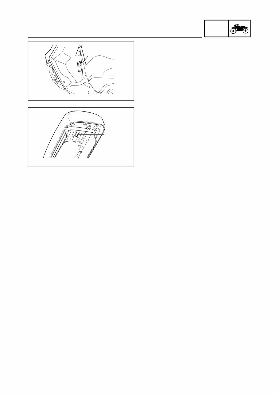
1-1 GEN INFO SCOOTER IDENTIFICATION EAS00015 GENERAL INFORMATION SCOOTER IDENTIFICATION EAS00017 VEHICLE IDENTIFICATION NUMBER The vehicle identification number 1 is stamped into the frame. EAS00018 MODEL LABEL The model label 1 is affixed to the frame under the seat. This information will be needed to or- der spare parts. 1 1
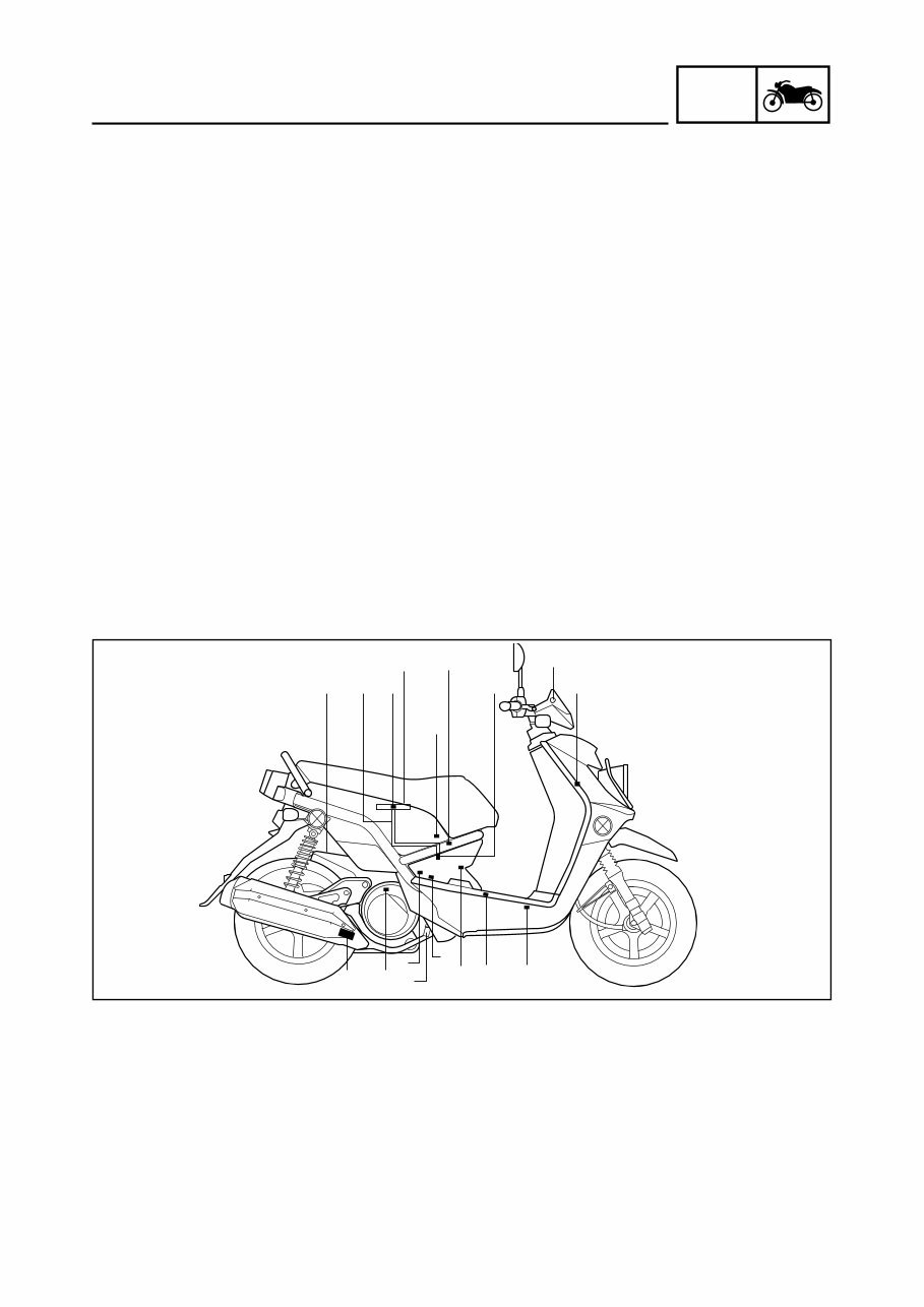
1-2 GEN INFO EAS00896 FEATURES OUTLINE OF THE FI SYSTEM The main function of a fuel supply system is to provide fuel to the combustion chamber at the opti- mum air-fuel ratio in accordance with the engine operating conditions and the atmospheric tempera- ture. In the conventional carburetor system, the air-fuel ratio of the mixture that is supplied to the combustion chamber is created by the volume of the intake air and the fuel that is metered by the jet used in the respective carburetor. Despite the same volume of intake air, the fuel volume requirement varies by the engine operating conditions, such as acceleration, deceleration, or operation under a heavy load. Carburetors that meter the fuel through the use of jets have been provided with various auxiliary devices, so that an optimum air-fuel ratio can be achieved to accommodate the constant changes in the operating con- ditions of the engine. As the requirements for the engine to deliver more performance and cleaner exhaust gases in- crease, it becomes necessary to control the air-fuel ratio in a more precise and finely tuned manner. To accommodate this need, this model has adopted an electronically controlled fuel injection(FI) system, in place of the conventional carburetor system. This system can achieve an optimum air- fuel ratio required by the engine at all times by using a microprocessor that regulates the fuel injec- tion volume according to the engine operating conditions detected by various sensors. The adoption of the FI system has resulted in a highly precise fuel supply, improved engine re- sponse, better fuel economy, and reduced exhaust emissions. 1 ECU 2 Engine trouble warning light 3 Lean angle cut-off switch 4 Fuel hose 5 Ignition coil 6 Fuel injector 7 Intake air pressure sensor 8 ISC(idle speed control) valve 9 Intake air temperature sensor 0 Battery q Air filter case w Catalytic converter e Crankshaft position sensor r Engine temperature sensor t Spark plug y Fuel tank u Fuel pump i Throttle position sensor o O 2 sensor FEATURES q 4 7 9 i u y 8 6 1 2 3 0 t e w o 5 r
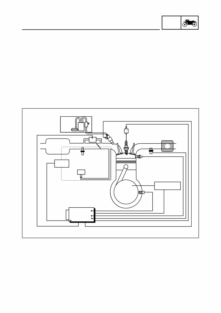
1-3 GEN INFO FEATURES EAS00897 FI SYSTEM The fuel pump delivers fuel to the fuel injector via the fuel filter. The pressure regulator maintains the fuel pressure that is applied to the fuel injector at only 250 kPa (2.5 kgf/cm 2 , 35.6 psi). Accordingly, when the energizing signal from the ECU energizes the fuel injector, the fuel passage opens, caus- ing the fuel to be injected into the intake manifold only during the time the passage remains open. Therefore, the longer the length of time the fuel injector is energized (injection duration), the greater the volume of fuel that is supplied. Conversely, the shorter the length of time the fuel injector is energized (injection duration), the lesser the volume of fuel that is supplied. The injection duration and the injection timing are controlled by the ECU. Signals that are input from the crankshaft position sensor, intake air pressure sensor, intake temperature sensor and engine temperature sensor enable the ECU to determine the injection duration. The injection timing is deter- mined through the signals from the crankshaft position sensor. As a result, the volume of fuel that is required by the engine can be supplied at all times in accordance with the driving conditions. 1 Fuel pump 2 Fuel injector 3 Ignition coil 4 ECU 5 Catalytic converter 6 Engine temperature sensor 7 Crankshaft position sensor 8 Intake air pressure sensor 9 Throttle body assembly 0 Intake air temperature sensor Illustration is for reference only. q Air filter case w ISC (idle speed control) valve e Throttle position sensor r O 2 sensor A Fuel system B Air system C Control system 5 1 A 3 4 6 7 9 0 q e w C MAQS B 8 REC./REG. 2 r
This is a comprehensive service and repair manual designed for PC, MAC, tablets, and smartphones. It provides detailed instructions, wiring diagrams, and pictures for easy repair jobs, including routine maintenance.
The manual is available in English and is compatible with Win/MAC/Linux. It can be instantly accessed without any shipping costs, making it convenient for immediate use.
With a user-friendly layout, this manual covers all repair procedures in great detail, helping users better understand all parts and repair processes. It empowers users to perform their own servicing, maintenance, and repairs.
All models for the specified years and engine types are included in the manual, which is packed with comprehensive service, repair, and maintenance information.
Upon payment via Credit/Debit/Paypal Account, the manual is instantly delivered, eliminating the need for shipping. This allows users to start their repairs without delay.
By using this manual, users can save significant amounts of money, avoiding overpriced services from mechanics, technicians, or engineers. The manual is easy to use and compatible with any PC/MAC computer.





 Lifetime Access




