EB000000 YZF-R6 SERVICE MANUAL 1998 by Yamaha Motor Co., Ltd. First edition, August 1998 All rights reserved. Any reproduction or unauthorized use without the written permission of Yamaha Motor Co., Ltd. is expressly prohibited.
NOTE: WARNING CAUTION: EB001000 NOTICE This manual was produced by the Yamaha Motor Company, Ltd. primarily for use by Yamaha dealers and their qualified mechanics. it is not possible to include all the knowledge of a mechanic in one manu- al. Therefore, anyone who uses this book to perform maintenance and repairs on Yamaha vehicles should have a basic understanding of mechanics and the techniques to repair these types of vehicles. Repair and maintenance work attempted by anyone without this knowledge is likely to render the ve- hicle unsafe and unfit for use. Yamaha Motor Company, Ltd. is continually striving to improve all of its models. Modifications and sig- nificant changes in specifications or procedures will be forwarded to all authorized Yamaha dealers and will appear in future editions of this manual where applicable. Designs and specifications are subject to change without notice. EB002000 IMPORTANT MANUAL INFORMATION Particularly important information is distinguished in this manual by the following. The Safety Alert Symbol means ATTENTION! BECOME ALERT! YOUR SAFETY IS INVOLVED! Failure to follow WARNING instructions could result in severe injury or death to the motorcycle operator, a bystander or a person checking or repairing the mo- torcycle. A CAUTION indicates special precautions that must be taken to avoid damage to the motorcycle. NOTE: A NOTE provides key information to make procedures easier or clearer.
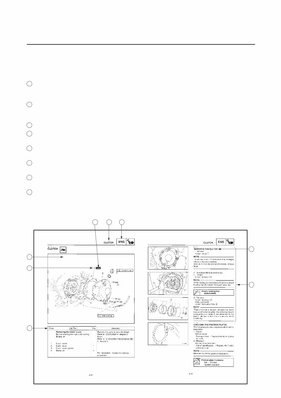
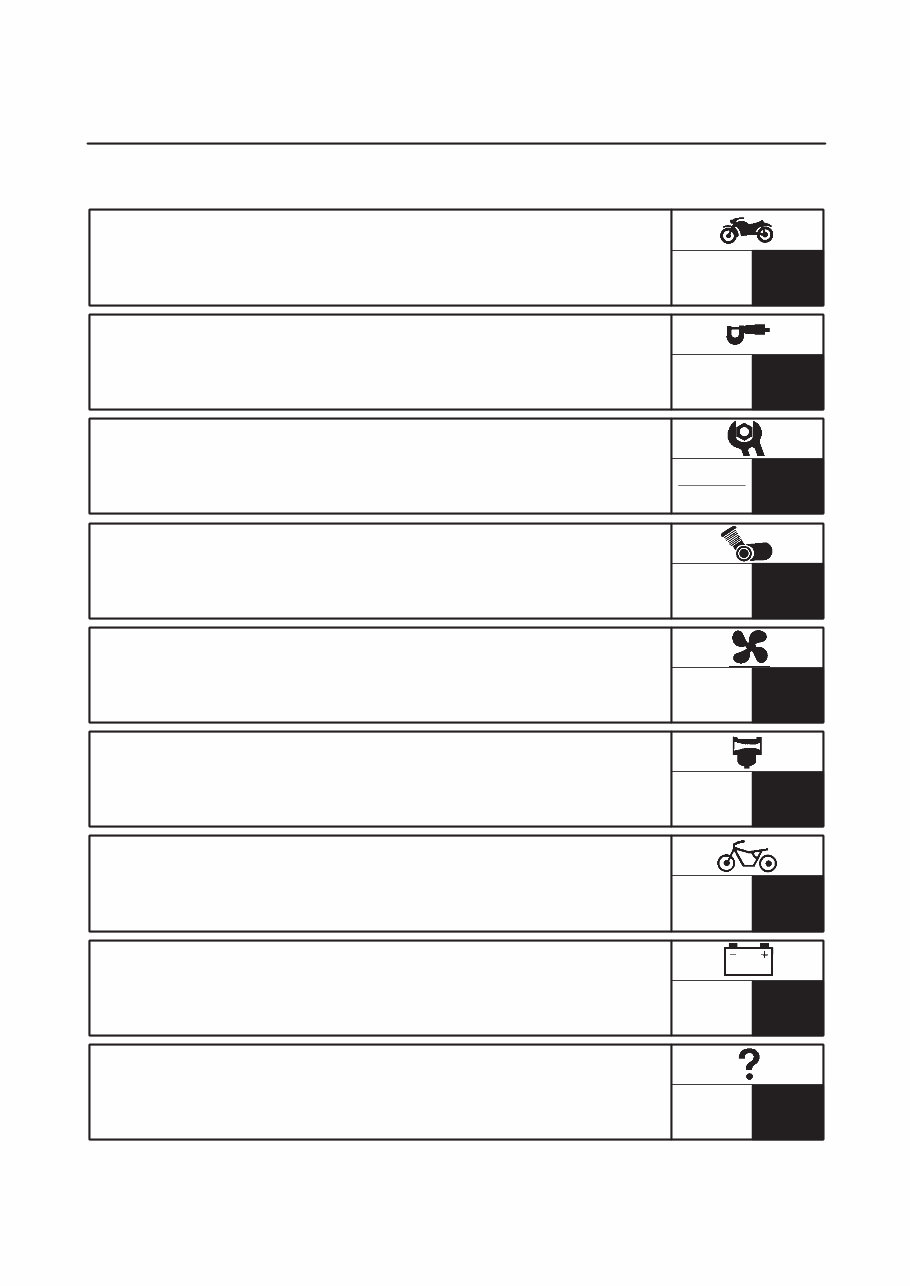
1 2 6 4 5 7 3 8 EB003000 HOW TO USE THIS MANUAL This manual is intended as a handy, easy-to-read reference book for the mechanic. Comprehensive explanations of all installation, removal, disassembly, assembly, repair and check procedures are laid out with the individual steps in sequential order. 1 The manual is divided into chapters. An abbreviation and symbol in the upper right corner of each page indicate the current chapter. Refer to “SYMBOLS”. 2 Each chapter is divided into sections. The current section title is shown at the top of each page, except in Chapter 3 (“PERIODIC CHECKS AND ADJUSTMENTS”), where the sub-section title(-s) ap- pears. 3 Sub-section titles appear in smaller print than the section title. 4 To help identify parts and clarify procedure steps, there are exploded diagrams at the start of each removal and disassembly section. 5 Numbers are given in the order of the jobs in the exploded diagram. A circled number indicates a disassembly step. 6 Symbols indicate parts to be lubricated or replaced. Refer to “SYMBOLS”. 7 A job instruction chart accompanies the exploded diagram, providing the order of jobs, names of parts, notes in jobs, etc. 8 Jobs requiring more information (such as special tools and technical data) are described sequen- tially.
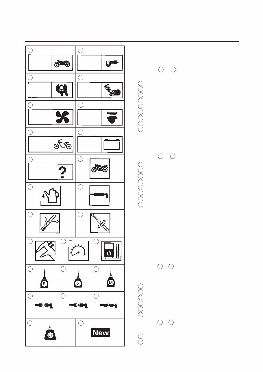
22 1 3 5 7 9 2 4 8 6 24 25 23 21 19 20 18 16 17 15 14 13 11 12 10 GEN INFO SPEC ENG CARB ELEC CHAS COOL CHK ADJ TRBL SHTG EB004000 SYMBOLS The following symbols are not relevant to every vehicle. Symbols 1 to 9 indicate the subject of each chapter. 1 General information 2 Specifications 3 Periodic checks and adjustments 4 Engine 5 Cooling system 6 Carburetor(-s) 7 Chassis 8 Electrical system 9 Troubleshooting Symbols 10 to 17 indicate the following. 10 Serviceable with engine mounted 11 Filling fluid 12 Lubricant 13 Special tool 14 Tightening torque 15 Wear limit, clearance 16 Engine speed 17 Electrical data Symbols 18 to 23 in the exploded diagrams indi- cate the types of lubricants and lubrication points. 18 Engine oil 19 Gear oil 20 Molybdenum disulfide oil 21 Wheel bearing grease 22 Lithium soap base grease 23 Molybdenum disulfide grease Symbols 24 to 25 in the exploded diagrams indi- cate the following. 24 Apply locking agent (LOCTITE ) 25 Replace the part
GENERAL INFORMATION SPECIFICATIONS PERIODIC INSPECTION AND ADJUSTMENT ENGINE OVERHAUL COOLING SYSTEM CARBURETORS CHASSIS ELECTRICAL TROUBLESHOOTING GEN INFO 1 SPEC 2 3 ENG 4 COOL 5 CARB 6 CHAS 7 ELEC 8 TRBL SHTG 9 CHK ADJ INDEX
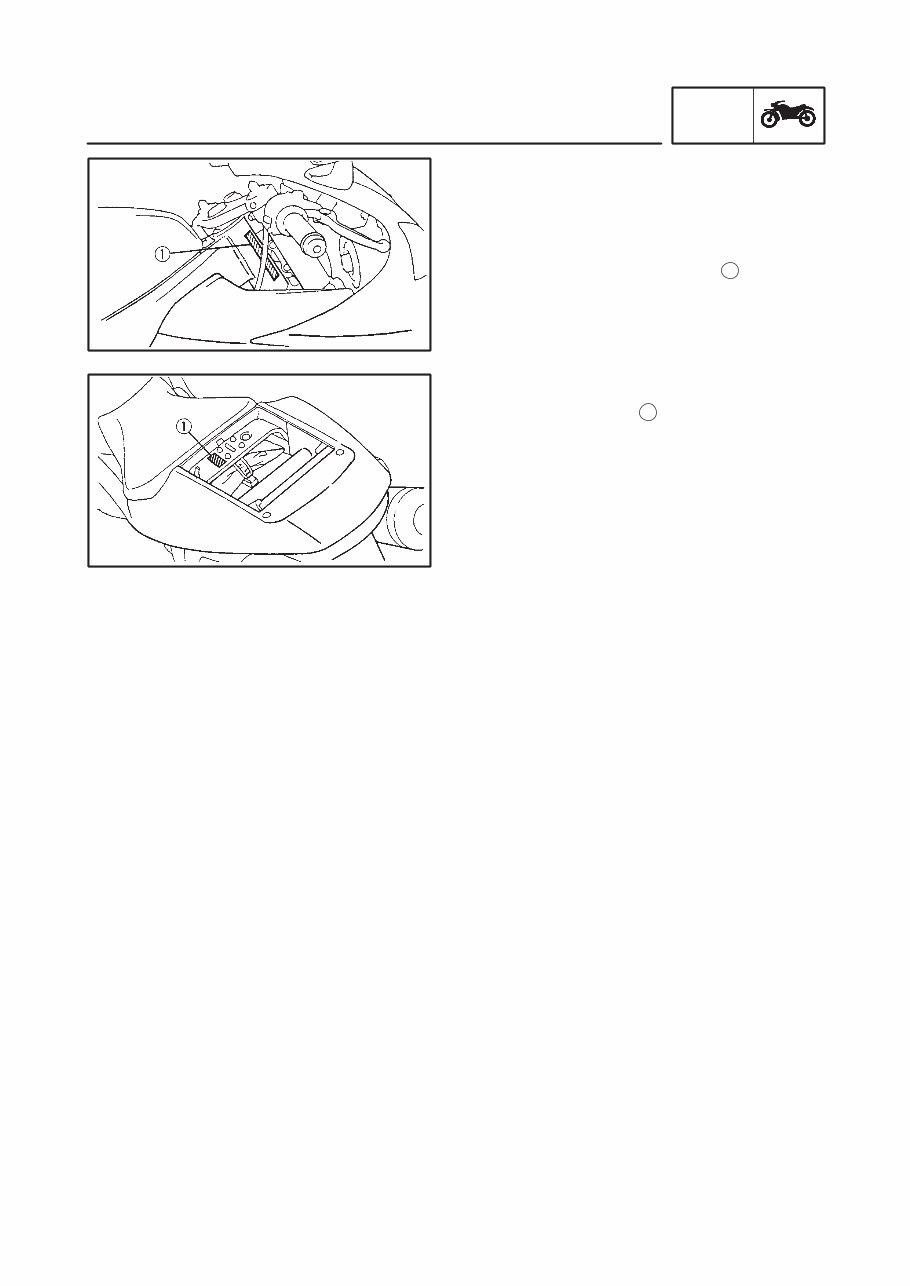
1-1 MOTORCYCLE IDENTIFICATION GEN INFO EB100000 GENERAL INFORMATION MOTORCYCLE IDENTIFICATION EB100010 VEHICLE IDENTIFICATION NUMBER The vehicle identification number 1 is stamped into the right side of the steering head pipe. EB100020 MODEL CODE The model code label 1 is affixed to the frame. This information will be needed to order spare parts.
1-2 IMPORTANT INFORMATION GEN INFO EB102000 IMPORTANT INFORMATION PREPARATION FOR REMOVAL AND DIS- ASSEMBLY 1. Before removal and disassembly, remove all dirt, mud, dust, and foreign material. 2. Use only the proper tools and cleaning equipment. Refer to “SPECIAL TOOLS”. 3. When disassembling, always keep mated parts together. This includes gears, cylin- ders, pistons and other parts that have been “mated” through normal wear. Mated parts must always be reused or replaced as an as- sembly. 4. During disassembly, clean all of the parts and place them in trays in the order of disas- sembly. This will speed up assembly and al- low for the correct installation of all parts. 5. Keep all parts away from any source of fire. EB102010 REPLACEMENT PARTS Use only genuine Yamaha parts for all replace- ments. Use oil and grease recommended by Yamaha for all lubrication jobs. Other brands may be similar in function and ap- pearance, but inferior in quality. EB102020 GASKETS, OIL SEALS AND O-RINGS 1. When overhauling the engine, replace all gaskets, seals, and O-rings. All gasket sur- faces, oil seal lips, and O-rings must be cleaned. 2. During reassembly, properly oil all mating parts and bearings and lubricate the oil seal lips with grease.
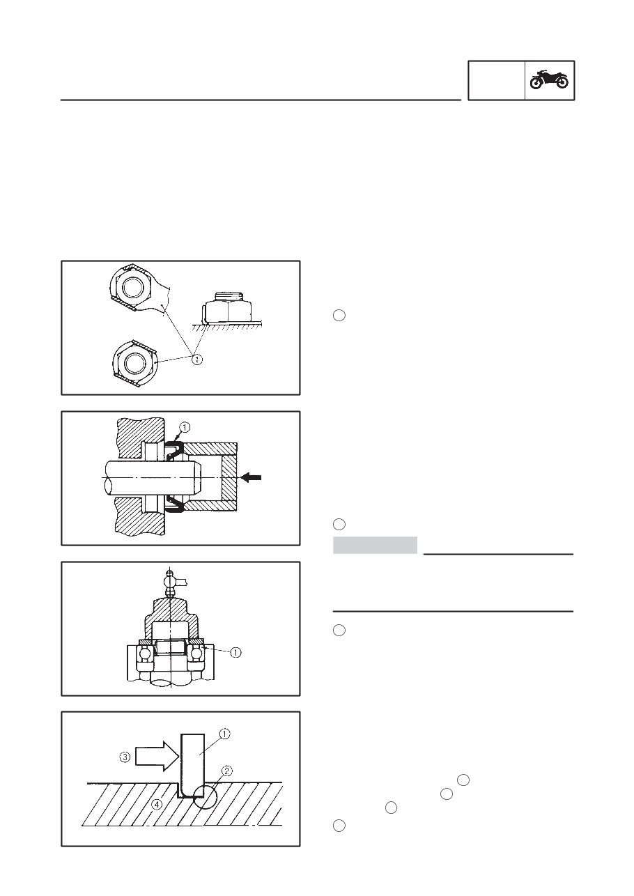
1-3 IMPORTANT INFORMATION GEN INFO CAUTION: USING A DYNAMOMETER The YZF-R6 has a carbon muffler that may change color when exposed to high tempera- tures. Therefore, when using a dynamometer always use a fan to cool the muffler. EB102030 LOCK WASHERS/PLATES AND COTTER PINS After removal, replace all lock washers / plates 1 and cotter pins. After the bolt or nut has been tightened to specification, bend the lock washer tabs and the cotter pin ends along a flat of the bolt or nut. EB102040 BEARINGS AND OIL SEALS 1. Install bearings and oil seals so that the manufacturer’s marks or numbers are vis- ible. When installing oil seals, lubricate the oil seal lips with a light coat of lithium soap base grease. Oil bearings liberally when installing, if appropriate. 1 Oil seal Do not spin the bearing with compressed air because this will damage the bearing sur- faces. 1 Bearing EB102050 CIRCLIPS Before reassembly, check all circlips carefully and replace damaged or distorted circlips. Al- ways replace piston pin clips after one use. When installing a circlip 1 , make sure that the sharp-edged corner 2 is positioned opposite the thrust 3 that the circlip receives. 4 Shaft
This manual contains all the necessary instructions needed for any repair of your Yamaha R6.
It provides the same information that dealer technicians and mechanics use to diagnose and repair your bike.
Whether it's routine maintenance, such as tune-ups and brake service, or more extensive repairs involving engine/clutch disassembly, this manual provides the most reliable information to perform the job.
Accurate, clear, and concise text, combined with detailed illustrations, make it possible for anyone with even a bit of basic mechanical knowledge to safely and easily service and repair their bike.
Comprehensive diagrams, in-depth illustrations, and all the manufacturer's specifications and technical information you will need are included.
Not only is this a complete repair manual, but it also includes all the scheduled service information, tech service bulletins, and recall information.