


YZF-R6T
5SL-28197-12
SUPPLEMENTARY
SERVICE MANUAL
LIT-11616-18-45
YZF-R6TC

YZF-R6T / YZF-R6TC
SUPPLEMENTARY
SERVICE MANUAL
©2004 by Yamaha Motor
Corporation, U.S.A.
First edition, September 2004
All rights reserved. Any reproduction
or unauthorized use without the written
permission of Yamaha Motor Corporation,
U.S.A. is expressly prohibited.
Printed in U.S.A.
P / N LIT-11616-18-45
EAS00001
FOREWORD
This Supplementary Service Manual has been prepared to introduce new service and data for the
YZF-R6T / YZF-R6TC. For complete service information procedures it is necessary to use this Sup-
plementary Service Manual together with the following manual.
YZF-R6R / YZF-R6SR / YZF-R6RC / YZF-R6SRC SERVICE MANUAL:
LIT-11616-16-45 (5SL-28197-10)
YZF-R6S / YZF-R6SC SUPPLEMENTARY SERVICE MANUAL: LIT-11616-17-46 (5SL-28197-11)
EAS00030
NOTICE
This manual was produced by the Yamaha Motor Company, Ltd. primarily for use by Yamaha deal-
ers and their qualified mechanics. It is not possible to include all the knowledge of a mechanic in one
manual. Therefore, anyone who uses this book to perform maintenance and repairs on Yamaha
vehicles should have a basic understanding of mechanics and the techniques to repair these types
of vehicles. Repair and maintenance work attempted by anyone without this knowledge is likely to
render the vehicle unsafe and unfit for use.
This model has been designed and manufactured to perform within certain specifications in regard
to performance and emissions. Proper service with the correct tools is necessary to ensure that the
vehicle will operate as designed. If there is any question about a service procedure, it is imperative
that you contact a Yamaha dealer for any service information changes that apply to this model. This
policy is intended to provide the customer with the most satisfaction from his vehicle and to conform
to federal environmental quality objectives.
Yamaha Motor Company, Ltd. is continually striving to improve all of its models. Modifications and
significant changes in specifications or procedures will be forwarded to all authorized Yamaha deal-
ers and will appear in future editions of this manual where applicable.
NOTE:
• This Service Manual contains information regarding periodic maintenance to the emission control
system. Please read this material carefully.
• Designs and specifications are subject to change without notice.
EAS00040
IMPORTANT MANUAL INFORMATION
Particularly important information is distinguished in this manual by the following.
The Safety Alert Symbol means ATTENTION! BECOME ALERT! YOUR
SAFETY IS INVOLVED!
Failure to follow WARNING instructions could result in severe injury or death
to the motorcycle operator, a bystander or a person checking or repairing the
motorcycle.
A CAUTION indicates special precautions that must be taken to avoid dam-
age to the motorcycle.
A NOTE provides key information to make procedures easier or clearer.
WARNING
CAUTION:
NOTE:
EAS00007
HOW TO USE THIS MANUAL
This manual is intended as a handy, easy-to-read reference book for the mechanic. Comprehensive
explanations of all installation, removal, disassembly, assembly, repair and check procedures are
laid out with the individual steps in sequential order.
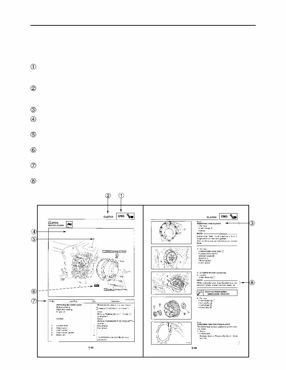
The manual is divided into chapters. An abbreviation and symbol in the upper right corner of
each page indicate the current chapter.
Refer to “SYMBOLS”.
Each chapter is divided into sections. The current section title is shown at the top of each page,
except in Chapter 3 (“PERIODIC CHECKS AND ADJUSTMENTS”), where the sub-section title(s)
appears.
Sub-section titles appear in smaller print than the section title.
To help identify parts and clarify procedure steps, there are exploded diagrams at the start of
each removal and disassembly section.
Numbers are given in the order of the jobs in the exploded diagram. A circled number indicates a
disassembly step.
Symbols indicate parts to be lubricated or replaced.
Refer to “SYMBOLS”.
A job instruction chart accompanies the exploded diagram, providing the order of jobs, names of
parts, notes in jobs, etc.
Jobs requiring more information (such as special tools and technical data) are described
sequentially.
EAS00008
SYMBOLS
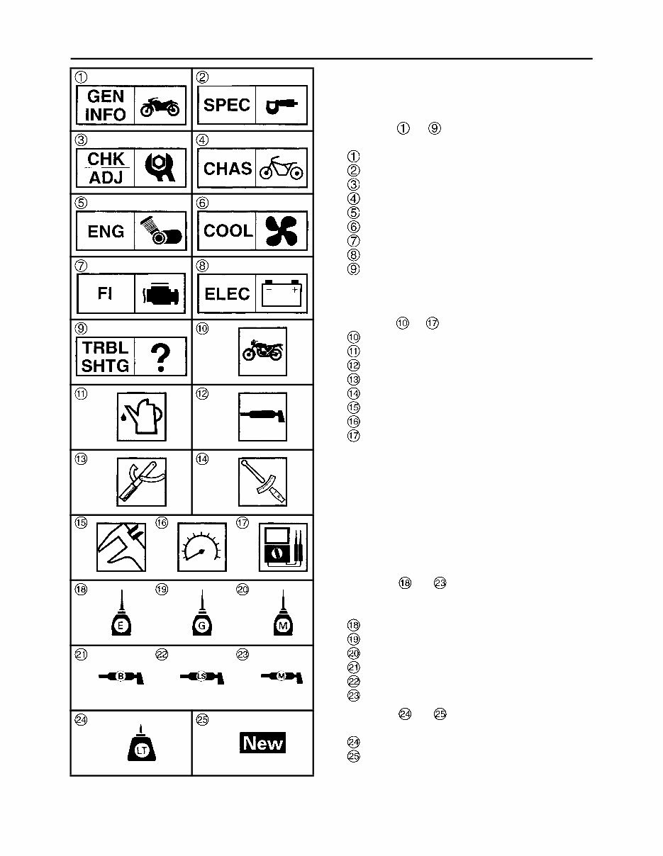
The following symbols are not relevant to every
vehicle.
Symbols to indicate the subject of each
chapter.
General information
Specifications
Periodic checks and adjustments
Chassis
Engine
Cooling system
Fuel injection system
Electrical system
Troubleshooting
Symbols to indicate the following.
Serviceable with engine mounted
Filling fluid
Lubricant
Special tool
Tightening torque
Wear limit, clearance
Engine speed
Electrical data
Symbols to in the exploded diagrams
indicate the types of lubricants and lubrication
points.
Engine oil
Gear oil
Molybdenum-disulfide oil
Wheel-bearing grease
Lithium-soap-based grease
Molybdenum-disulfide grease
Symbols to in the exploded diagrams
indicate the following.
Apply locking agent (LOCTITE
®
)
Replace the part

CONTENTS
GENERAL INFORMATION
SPECIAL TOOLS . . . . . . . . . . . . . . . . . . . . . . . . . . . . . . . . . . . . . . . . . 1
SPECIFICATIONS
GENERAL SPECIFICATIONS . . . . . . . . . . . . . . . . . . . . . . . . . . . . . . . 2
ENGINE SPECIFICATIONS . . . . . . . . . . . . . . . . . . . . . . . . . . . . . . . . . 2
CHASSIS SPECIFICATIONS. . . . . . . . . . . . . . . . . . . . . . . . . . . . . . . . 3
ELECTRICAL SPECIFICATIONS . . . . . . . . . . . . . . . . . . . . . . . . . . . . 4
TIGHTENING TORQUES . . . . . . . . . . . . . . . . . . . . . . . . . . . . . . . . . . . 5
ENGINE TIGHTENING TORQUES . . . . . . . . . . . . . . . . . . . . . . . . 5
CHASSIS TIGHTENING TORQUES . . . . . . . . . . . . . . . . . . . . . . . 5
CABLE ROUTING . . . . . . . . . . . . . . . . . . . . . . . . . . . . . . . . . . . . . . . . 6
PERIODIC CHECKS AND ADJUSTMENTS
BLEEDING THE HYDRAULIC BRAKE SYSTEM . . . . . . . . . . . . . . 20
ADJUSTING THE FRONT FORK LEGS. . . . . . . . . . . . . . . . . . . . . 22
CHASSIS
FRONT WHEEL AND BRAKE DISCS . . . . . . . . . . . . . . . . . . . . . . . . . 24
FRONT AND REAR BRAKES . . . . . . . . . . . . . . . . . . . . . . . . . . . . . . . 25
FRONT BRAKE PADS . . . . . . . . . . . . . . . . . . . . . . . . . . . . . . . . . . 25
FRONT BRAKE MASTER CYLINDER . . . . . . . . . . . . . . . . . . . . . . 26
FRONT BRAKE CALIPERS . . . . . . . . . . . . . . . . . . . . . . . . . . . . . . 29
ASSEMBLING AND INSTALLING THE FRONT BRAKE MASTER
CYLINDER . . . . . . . . . . . . . . . . . . . . . . . . . . . . . . . . . . . . . . . . . . . 31
FRONT FORK . . . . . . . . . . . . . . . . . . . . . . . . . . . . . . . . . . . . . . . . . . . 33
FRONT FORK LEGS . . . . . . . . . . . . . . . . . . . . . . . . . . . . . . . . . . . 33
DISASSEMBLING THE FRONT FORK LEGS . . . . . . . . . . . . . . . . 36
CHECKING THE FRONT FORK LEGS . . . . . . . . . . . . . . . . . . . . . 37
ASSEMBLING THE FRONT FORK LEGS . . . . . . . . . . . . . . . . . . . 38
SWINGARM AND DRIVE CHAIN . . . . . . . . . . . . . . . . . . . . . . . . . . . . 43
CHECKING THE DRIVE CHAIN . . . . . . . . . . . . . . . . . . . . . . . . . . . 43
COOLING SYSTEM
RADIATOR . . . . . . . . . . . . . . . . . . . . . . . . . . . . . . . . . . . . . . . . . . . . . . 45

ELECTRICAL SYSTEM
ELECTRIC STARTING SYSTEM. . . . . . . . . . . . . . . . . . . . . . . . . . . . . 47
CIRCUIT DIAGRAM . . . . . . . . . . . . . . . . . . . . . . . . . . . . . . . . . . . . 47
TROUBLESHOOTING . . . . . . . . . . . . . . . . . . . . . . . . . . . . . . . . . . 48
COOLING SYSTEM . . . . . . . . . . . . . . . . . . . . . . . . . . . . . . . . . . . . . . . 51
CIRCUIT DIAGRAM . . . . . . . . . . . . . . . . . . . . . . . . . . . . . . . . . . . . 51
TROUBLESHOOTING . . . . . . . . . . . . . . . . . . . . . . . . . . . . . . . . . . 52
YZF-R6T / YZF-R6TC WIRING DIAGRAM
GEN
INFO
1
EAS00027
GENERAL INFORMATION
SPECIAL TOOLS
The following special tools are necessary for complete and accurate tune-up and assembly. Use
only the appropriate special tools as this will help prevent damage caused by the use of inappropri-
ate tools or improvised techniques. Special tools, part numbers or both may differ depending on the
country. When placing an order, refer to the list provided below to avoid any mistakes.
NOTE:
• For U.S.A. and Canada, use part number starting with “YM-”, “YU-”, or “ACC-”.
• For others, use part number starting with “90890-”.
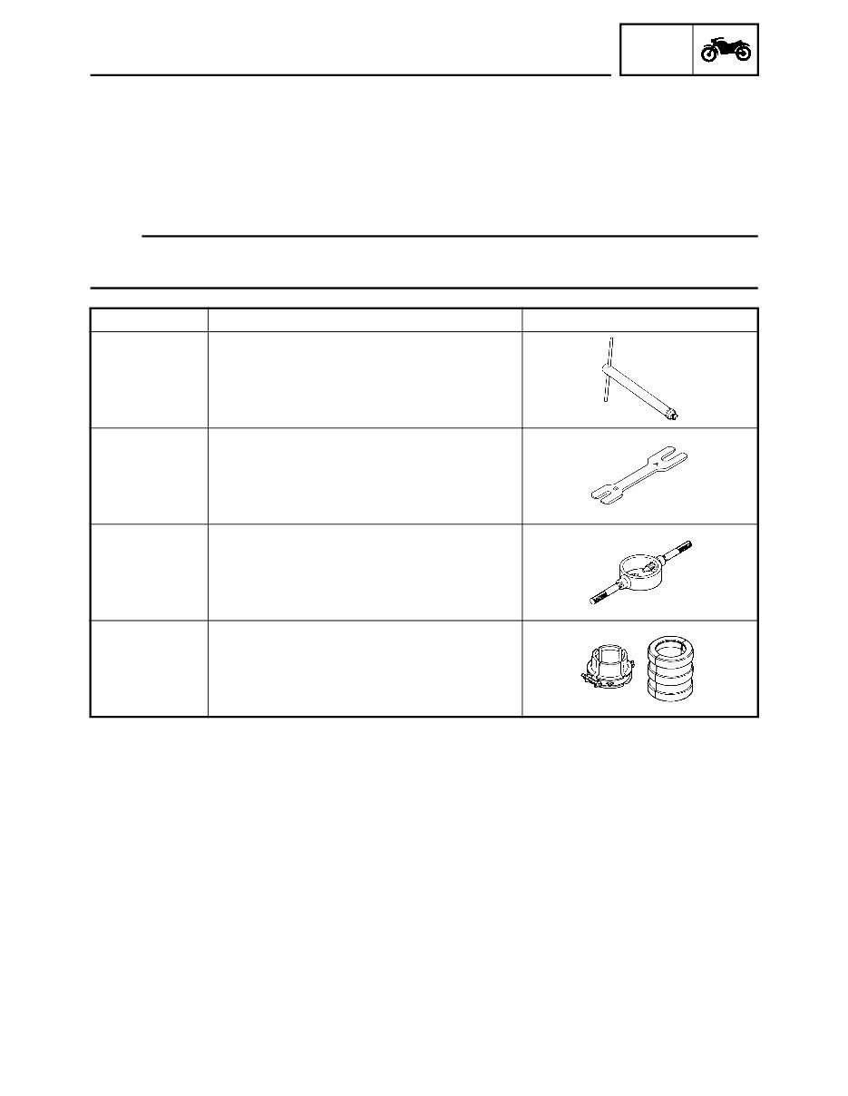
Tool No. Tool name / Function Illustration
90890-01423
YM-01423
Damper rod holder
This tool is used to hold the damper rod
assembly when loosening or tightening the
damper rod assembly bolt.
90890-01434
YM-01434
Rod holder
This tool is used to support the damper
adjusting rod.
90890-01441
YM-01441
Fork spring compressor
This tool is used to disassemble or assemble
the front fork legs.
90890-01442
YM-01442
Fork seal driver
This tool is used to install the front fork’s oil
seal and dust seal.
SPECIAL TOOLS
SPEC
2
SPECIFICATIONS
GENERAL SPECIFICATIONS
ENGINE SPECIFICATIONS
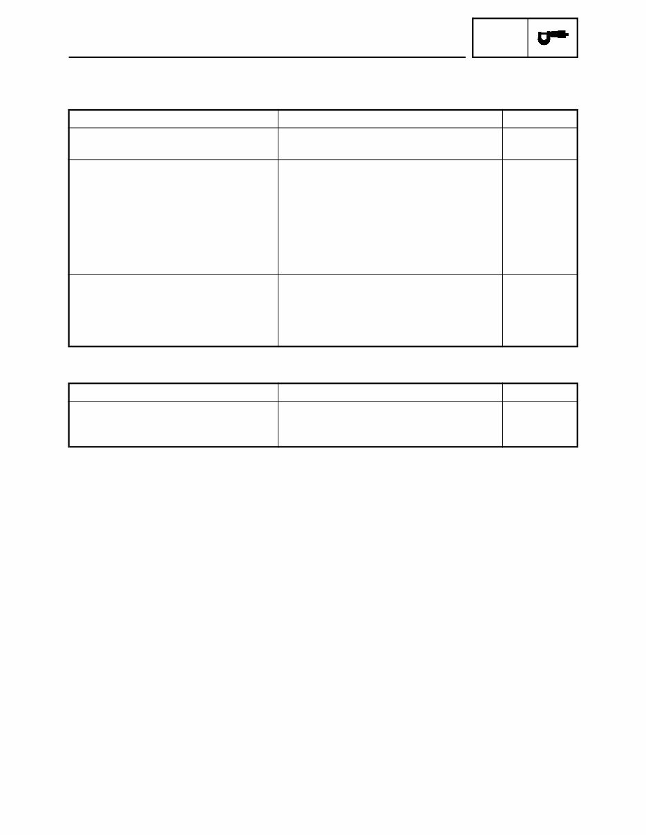
Item Standard Limit
Model code 5SLR (USA except for CAL) • • •
5SLS (CAL)
Dimensions
Overall length 2,045 mm (80.5 in) • • •
Overall width
690 mm (27.2 in)
• • •
Overall height 1,105 mm (43.5 in) • • •
Seat height 830 mm (32.7 in) • • •
Wheelbase 1,385 mm (54.5 in) • • •
Minimum ground clearance 145 mm (5.7 in) • • •
Minimum turning radius 3,800 mm (149.6 in) • • •
Weight
Wet (with oil and a full fuel tank) 183 kg (404 lb) (USA except for CAL) • • •
184 kg (406 lb) (CAL) • • •
Maximum load (except motorcycle) 192 kg (423 lb) (USA except for CAL) • • •
191 kg (421 lb) (CAL) • • •
Item Standard Limit
Throttle bodies
Model (manufacturer) × quantity 40EIS (MIKUNI) × 4 • • •
ID mark 5SLM 30 (5SLR), 5SLS 40 (5SLS) • • •
GENERAL SPECIFICATIONS / ENGINE SPECIFICATIONS
SPEC
3
CHASSIS SPECIFICATIONS
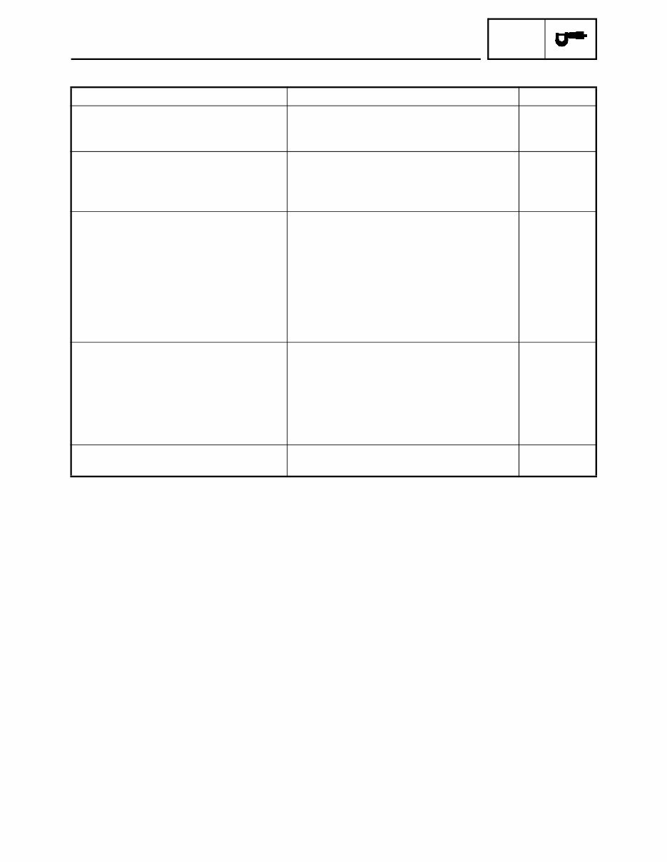
Item Standard Limit
Frame
Caster angle 24.5° • • •
Trail 95 mm (3.74 in) • • •
Front tire
Size 120 / 70 ZR17 M / C (55W) • • •
Model (manufacturer) Pilot POWER C (MICHELIN) • • •
D218FM (DUNLOP)
Rear tire
Model (manufacturer) Pilot POWER (MICHELIN) • • •
D218M (DUNLOP)
Tire pressure (cold)
0 ~ 90 kg (0 ~ 198 lb) 290 kPa (2.9 kgf / cm
2
, 2.9 bar, 41.3 psi) • • •
90 ~ 192 kg (198 ~ 426 lb) 290 kPa (2.9 kgf / cm
2
, 2.9 bar, 41.3 psi) • • •
(USA except for CAL)
90 ~ 191 kg (198 ~ 423 lb) (CAL) 290 kPa (2.9 kgf / cm
2
, 2.9 bar, 41.3 psi) • • •
High-speed riding 290 kPa (2.9 kgf / cm
2
, 2.9 bar, 41.3 psi) • • •
Front brakes
Brake lever free play 6.7 ~ 18.1 mm (0.26 ~ 0.71 in) • • •
Brake discs
Diameter × thickness 310 × 4.5 mm (12.20 × 0.18 in) • • •
Min. thickness • • • 4.0 mm
(0.16 in)
Master cylinder inside diameter 16 mm (0.63 in) • • •
Rear brake
Brake pedal freeplay 4.3 ~ 9.0 mm (0.17 ~ 0.35 in) • • •
CHASSIS SPECIFICATIONS
You're Reading a Preview
What's Included?
 Lifetime Access
Fast Download Speeds
Online & Offline Access
Access PDF Contents & Bookmarks
Full Search Facility
Print one or all pages of your manual
$35.99
2007 Yamaha YZF-R6S Motorcycle Service Manual
Viewed 52 Times Today

What's Included?
Lifetime Access
Fast Download Speeds
Online & Offline Access
Access PDF Contents & Bookmarks
Full Search Facility
Print one or all pages of your manual
$35.99

Secure transaction
What's Included?
Lifetime Access
Fast Download Speeds
Online & Offline Access
Access PDF Contents & Bookmarks
Full Search Facility
Print one or all pages of your manual
Description
This manual covers the 2007 Yamaha YZF-R6S motorcycle service manual. It is a comprehensive guide used by professional mechanics and DIY enthusiasts for repairs and maintenance.


